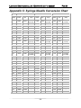
1
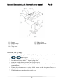
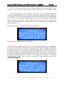
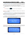
Lab-scale Electrospinning unit (Electroris) user’s mannual Fnm Co. Fanavaran Nano-Meghyas Lab-Scale Electrospinning Unit (Electroris) user’s mannual 2013 Fnm.ir 1 Lab-scale Electrospinning unit (Electroris) user’s mannual Fnm Co. General Information ...............................................................................................3 Calibration ............................................................................................................ 3 Warranty ............................................................................................................. 3 Repair Facilities and Parts ..................................................................................... 4 Grounding the System (Earth): ............................................................................... 4 GENERAL SAFETY SUMMARY ................................................................................ 4 The instrument limits: ........................................................................................... 6 Introduction..........................................................................................................6 Theory of Operation ............................................................................................... 6 Electrospinning Process ........................................................................................6 Syringe pump ........................................................................................................6 Keypad .................................................................................................................8 Syringe Table and Custom Syringes ........................................................................8 Target Volume ......................................................................................................8 Nonvolatile Memory ...............................................................................................8 Smooth injection: ..................................................................................................8 Adjusting the Pusher Block: ...................................................................................8 High Voltage Cable ................................................................................................8 Visual/Audible Alarm ..............................................................................................8 Package contents: ................................................................................................ 9 Installation: .......................................................................................................... 9 Physical installation ...............................................................................................9 Turning on the device: ............................................................................................9 Loading the Syringe............................................................................................. 10 Proper syringe selection: .....................................................................................11 Display System ................................................................................................... 11 User Interface .................................................................................................... 11 Data Entry Keys .................................................................................................12 Syringe pump (injection) system ...........................................................................12 Nozzle Scan System ............................................................................................15 Distance adjustment system: ..............................................................................16 The drum rotation speed: .....................................................................................16 Setting the temperature of chamber: ................................................................... 18 Set mode: ..........................................................................................................19 Lightening the chamber: ...................................................................................... 19 High Voltage Power Supply (HVPS) ....................................................................... 19 Appendix A: Syringe inside Diameter .....................................................................21 Appendix B: Set mode of Digital Temperature Controller .........................................22 Appendix C: Syringe Needle Conversion Chart ........................................................23 2 Lab-scale Electrospinning unit (Electroris) user’s mannual Fnm Co. General Information Serial Number All inquiries concerning our product should refer to the serial number of the unit. Serial numbers are located on the rear of the case. Calibration All electrospinning units are designed and manufactured to meet their performance specifications at all rated voltages and frequencies. It’s necessary to calibrate the instrument every 6 month. It’s suggested that choose a 10-mililitre syringe and a 1-mililitre target, then measure the amount of pedal (pusher block) movement forwards in 1, 6 and 60 ml/h. The movement must be 12.73 mm. To measure the accuracy of internal timer, the injection time must be 60, 10 and 1 minute(s). Warranty Fnm Electroris is warranted for a period of one year from date of purchasing. At its option, Fnm Co. will repair or replace the unit if it is found to be defective as to workmanship or material. The warranty does not extend to: Damage resulting from transportation, wrong connections with other systems, connection with defective equipments, voltage fluctuations, fire or intensive heat, water or corrosive chemicals, dust, lightning, natural disasters, collision, misusing the instrument or neglecting the manual description. The devices that have been repaired by other companies. The devices that have been manipulated. Damaging the instrument labels or holograms Damage resulting from installation or updating the files, software, program and firmware by irresponsible people. Damage resulting from not connecting the device to the earth. Damage resulting from connecting the high voltage wire to the body of device, drum, syring pump and etc. According to the warranty, our company will repair or replace the defective device free of charge. You can send us the defective part(s) of device (such as HV power supply or/and syringe pump) by post. We will accept any charge made for posting. 3 Lab-scale Electrospinning unit (Electroris) user’s mannual Fnm Co. Repair Facilities and Parts Fnm Co. stocks replacement and repair parts. While ordering, please describe parts as completely as possible. Preferably by using the part numbers, a sample or drawing. CAUTION Electroris use High-voltage power supply for generating nanofibers. The term high voltage usually means electrical energy at voltages high enough to inflict harm or death upon living things. High voltage can bridge long distances and break through the isolation. On the surrounding objects it can form a dangerous charge. If not properly connected to proper discharge resistor, capacitors can remain charged even long after shutdown. Sparks in air The dielectric breakdown strength of dry air, at Standard Temperature and Pressure (STP), between spherical electrodes is approximately 33 kV/cm. This is only as a rough guide, since the actual breakdown voltage is highly dependent upon the electrode shape and size. Strong electric fields (from high voltages applied to small or pointed conductors) often produce violet-colored corona discharges in air, as well as visible sparks. Grounding the System (Earth): Due to the high voltages required to form the polymeric nanofibres, it is necessary to ground the device through a grounding conductor of the power cord. Lack of a proper earth connection and electronic system failure can carry electrical shock risks to the operator. The screw at the back of device can be connected to the water metal pipe of the laboratory by a piece of wire. Maintenance and General Safety Summary GENERAL SAFETY SUMMARY Please read the following safety precautions to ensure proper use of your device. To avoid potential hazards and product damage, use this product only as instructed in this manual. If the equipment is used in a manner not specified by the manufacturer, the protection provided by the equipment may be impaired. 4 Lab-scale Electrospinning unit (Electroris) user’s mannual Fnm Co. To Prevent Hazard or Injury: Use Proper Line Cord Use only the specified line cord for this product and make sure line cord is certified for country of use. Use Proper Power Supply The unit is supplied with an approved power supply and line cord. To maintain the safety integrity of the device, use only one of the following power supplies: 200 – 240 V AC, 50-60 Hz Ground the Product This product is grounded through the grounding conductor of the power cord. To avoid electric shock, the grounding conductor must be connected to earth ground. Before making any connections to the input or output terminals of the product, ensure that the product is properly grounded. Make Proper Connections Make sure all connections are made properly and securely. Use Proper Fuse Use only specified fuses with product. Avoid Exposed Circuitry Do not touch any electronic circuitry inside of the product. Do Not Operate with Suspected Failures If damage is suspected on or to the device, do not operate it. Contact with qualified service personnel. Place the device in Proper Environment Review the operating manual for guidelines for proper operating environments. Keep the instrument in a dry, clean and flat place. Avoid connecting the ventilation fan near the walls. High viscosity solutions Don’t use high viscosity solutions and syringes with very low diameter nozzle (High gauges size). Finishing the solution Switch off the system after finishing the solution (Note: the target must always set at a suitable value). Clean the instrument Clean the keyboard and body of the instrument with a medium detergent. Oiling Oil the syringe pump screws and their connections in certain time. Nozzle Cleaning After finishing the work, clean inside of nozzle and connections completely, put a piece of thin wire inside the nozzle in order to avoid drying polymeric solution. 5 Lab-scale Electrospinning unit (Electroris) user’s mannual Fnm Co. Observe all Warning Labels on Product Read all labels on product to ensure proper usage. Using an organic solvent Notice that the used hose is able to solve in some organic solvents, so use Teflon or Polyethylene hose instead of PVC. Please inform FNM Co. staff if there is any problem. The instrument limits: Accuracy largely depends on the syringe and its diameter. Measurement error will directly cause the injection error. Warning: The sound alarm inside the device can be set up to warn the user when completing each order. Introduction Theory of Operation Electrospinning Process When a sufficiently high voltage is applied to a liquid droplet, the body of the liquid becomes charged, and electrostatic repulsion counteracts the surface tension and the droplet is stretched; at a critical point a stream of liquid erupts from the surface. This point of eruption is known as the Taylor cone. If the molecular cohesion of the liquid is sufficiently high, stream breakup does not occur (if it does, droplets are electrosprayed) and a charged liquid jet is formed. As the jet dries in flight, the mode of current flow changes from ohmic to convective as the charge migrates to the surface of the fiber. The jet is then elongated by a whipping process caused by electrostatic repulsion initiated at small bends in the fiber, until it is finally deposited on the grounded collector. The elongation and thinning of the fiber resulting from this bending instability leads to the formation of uniform fibers with nanometer-scale diameters. The standard laboratory setup for electrospinning consists of a spinneret (typically a syringe needle) connected to a high-voltage (5 to 50 kV) direct current power supply, a syringe pump, and a grounded collector. A polymer solution, sol-gel or particulate suspension is loaded into the syringe and this liquid is extruded from the needle tip at a constant rate by a syringe pump. Syringe pump The syringe pump of this device has been designed in order to use of a variety of syringes. The system is able to inject the certain volume of solution with different rates. All models 6 Lab-scale Electrospinning unit (Electroris) user’s mannual Fnm Co. employ a microcontroller which controls a small step angle stepping motor that drives a lead screw and Pusher Block. Micro-stepping techniques are employed to further reduce the step angle, eliminating flow pulsation. A keypad is used for entering the data to the pump. The diameter of the syringes is entered via the keypad and the internal microprocessor drives a precision stepper motor to produce accurate fluid flow. The pump can hold syringes of nonconductive materials (plastic or glass) make from about 1 μl to 50ml. Nonvolatile memory stores the last syringe diameter and flow rate along with other configuration data. Front of Electroris: 1: HVPS, 2: Drum collector, 3: System controller & panel, 4: Syringe pump Features Bright Display and Easy-To-Use Interface Using a 4-row 20-character LCD display cause to show the essential information, and its background light facilitates the reading of information in the darkness. Using 20 keys avoids the need for a multi-menu, so the system will be set and will start to operate by pressing a few keys. Different parameters such as flow rate, syringe diameter, maximum of injection, start & end scan position, scan speed and distance are adjustable. A functional key for each line of LCD gives easy access to sub-systems of Electroris. It will be discussed in detail later. Informational messages will be shown sometimes to indicate the setting of data out of range, or a problem. Pressing any key clears the message from the display. 7 Lab-scale Electrospinning unit (Electroris) user’s mannual Fnm Co. Keypad The keypad consists of 20 membrane keys. These keys are grouped into 3 sections: functional keys (L1, L2, L3 and L4), Data Entering keys (), and Operational keys. Syringe Table and Custom Syringes If a non-standard syringe is to be used, enter the inside diameter of the syringe in millimeters. Syringes are arranged according to manufacturer and material, and then according to size. (See Appendix A). Target Volume Specify the volume that is to be infused. The pump will run at the rate specified until this volume has been delivered in the Volume mode. Nonvolatile Memory All operational data entered into the pump from the keypad or from a computer will be stored, including the program. Smooth injection: Using a high accuracy motor and driver profiles deliver very smooth and consistent flow, that is virtually pulse free. Adjusting the Pusher Block: Using two keys that move the location of pusher block forward or backward can cause adjusting of its position rapidly. High Voltage Cable Before turning on the device, make sure that the cable is connected to nozzle(s). Connecting the high voltage cable to every part of the device (except the nozzle) causes transmission of high voltage to the device and can fail it. Also it can damage the high voltage power supply. Note: Before starting the machine, be sure that the high voltage power supply is off. Visual/Audible Alarm In addition to visual alarm devices, the device has an audio alarm that will sound in required times. 8 Lab-scale Electrospinning unit (Electroris) user’s mannual Fnm Co. Package contents: Contents of the Electroris package are Power cable, User manual, PVC hose, Earth cable and Fuse. In software models, software CD and USB cable is also included. Installation: Physical installation The following conditions must be noticed at the place where you work. A dry, clean and hard surface for keeping the instrument. Minimum of about 15 cm clearance around the device. suitable environmental conditions a proper ventilation Turning on the device: Plug in the power and then connect it to the input voltage of Electroris. Turn on main power switch located on the rear of device. Use black key on the right side of device to turning on the Electronic control section. The display will now illuminate indicating that the power connections are correct. The display will indicate FNM Co. internet address for 3 seconds. Then, the scan system will be activated and the nozzle will be set at zero. After that, the distance axis will set the drum at a 5cm-distance during this time the term "Set Zero" will be shown on the display. Use red key on the right side of device to turning on the High voltage power supply section. At this moment, the high voltage power supply is in standby mode that is shown by the blue LED. In this step the device is ready to use. 9 Lab-scale Electrospinning unit (Electroris) user’s mannual 4. 1. 4. 2. 4. 3. 4. 4. Syringe Syringe Clamp thumbscrew Clamp Screw Fnm Co. 4. 5. Pusher Blocks 4. 6. Stepper motor case 4. 7. Plastic case Loading the Syringe 1. Adjust the syringe pusher block (4.5) by pressing the positional switches 2. 3. 4. 5. 6. 7. on the keypad. Raise the spring loaded syringe retainer (4.3) and swing it out of the way. Lay the loaded syringe in the ‘V’ shaped syringe block. Swing the syringe retainer so it holds the syringe in place. Move the pusher block (4.5), using the positional switches, so it makes contact with the syringe plunger. Tighten down thumbscrews on syringe block bracket so that it captures flanges on syringe barrel. Tighten thumbscrew into place when switch is set. 10 Lab-scale Electrospinning unit (Electroris) user’s mannual Fnm Co. Proper syringe selection: Min Rate (Microliter/hour) = 0.5 * Syringe diameter (mm) ^ 2 Max Rate (Mililiter/hour) = 0.80 * Syringe diameter (mm) ^ 2 Example: a 1mm-diameter syringe: Min rate: 144.5 µl/h; Max rate: 231.2 ml/h a 10mm-diameter syringe: Min rate: 50 µl/h; Max rate: 80 ml/h a 17mm-diameter syringe: Min rate: 50 µl/h; Max rate: 80 ml/h Display System This screen consists of four rows(lines) that show the situation of each sub-system: First line: the injected volume of solution (ml) Second line: The position of nozzle(s) (per millimeter) Third line: The distance from the nozzle tip to the drum surface (mm) Fourth line: Drum rotation speed based on RPM Description 1: The keys L1, L2, L3 and L4 located on the left of each row are used to set each sub-system. Description 2: The last character on the right of each row indicates the moving (>) or stop ( | ) situation. User Interface The user interface consists of a keypad with a display area. The panel consists of a 4-row, 20-character alphanumeric vacuum green or blue fluorescent display, a 10-round volume drum rotation speed control, a system to control the chamber temperature, two LEDs (blue and red) and a switch to turn on and off the fluorescent lamps. 11 Lab-scale Electrospinning unit (Electroris) user’s mannual Fnm Co. The Keypad of Fnm electrospinning system Setting displays are used to facilitate entering data into the system software. Data entry will be discussed in detail later in this section. Informational messages occur at various times to indicate such items as a data setting out of range, or a detected problem such as the pump out of range flow rate. Pressing any key clears the message from the display. DESCRIPTION OF KEYS The keypad consists of 20 keys. The keys are used for entering control information and data into the device. Data Entry Keys Used to enter numeric data values or access special features. ENTER: Saves and stores displayed data value in memory when setting a data item. Cancel: Cancel the new displayed data and return the stored value. Syringe pump (injection) system The syringe pump can take one or two syringes make by nonconductive materials (plastic or glass syringes) and sizes below 50ml. The inner diameter of the syringe(s) is entered by the keyboard and the internal microprocessor calculates the cross-sectional area to calibrate the pump for that syringe. Note 1: Please be careful the hose is not soluble in the solvent. For example, PVC hose can be solved in most organic solvents. In the case, use Teflon or polyethylene hose. Note 2: At the end of electrospinning process, it is necessary to clean inside the nozzle(s) and tube. Then, put a piece of thin wire inside the nozzle(s) to avoid drying the polymeric solution. Note 3: The electricity can be transferred to the syringe through the tube, so the syringe shouldn’t be contaminated by the solution. If the syringe is contaminated, you will hear the discharge noise. In this time, should be turned off the “high voltage” and cleaned off the conaminated area immediately. 12 Lab-scale Electrospinning unit (Electroris) user’s mannual Fnm Co. Note 4: Most existing tubes are not strength enough to avoid passing high voltage electricity, so it’s necessary to keep tubes far away from devices such as syringe pumps. In the syringe pump, one or two syringes can be used. Using two syringes increases the amount of produced nanofiber. However, because of interaction between the formed polymer jets on the nozzles’ tip, using more than one syringe can alter the nanofiber size and its morphology. So, it’s better to use one syringe to optimize the process. If you use more than two syringes, the minimum distance between two nozzles should be about 4 cm, more or less, although this distance depends on the polymer, voltage and etc. (If you need more than two syringes, please contact with Fnm Co.) By pressing the key “L1” the following message will be shown: In this page 3 injection parameters are adjustable. Second Row (L2): “syringe inner diameter”: It’s the most important parameter in calculating the flow rate, so it’s necessary to measure and enter it correctly. When the syringe is changed, the new diameter value must be set. Units are in millimeters (mm). Enter the inside diameter (ID) of the syringe you wish to use. If you do not know your syringe diameter, refer to appendix A for nominal inside diameters of most popular syringes. For the greatest accuracy or if your syringe is not listed in appendix B, measure the inside diameter with a vernier caliper or other precision measuring tool. Record this value for future use. For setting it, press the key “L2” until the registered number blinks. Then, enter the new value by using the panel numeric keys (). 13 Lab-scale Electrospinning unit (Electroris) user’s mannual Fnm Co. Register or cancel the new value: For removing the last entered number, you can use the backspace key “”. In order to save the value, press just related line switch. For example, the key “L2” should be pressed to record the syringe diameter. To withdraw from the new value, you have to press “Cancel” on the key. So, the previous value will be shown again. Nonstop injection: In some versions, it must be to set Target in 0 to have a nonstop injection. Note: Pressing the key causes cancel or return to the higher stage. Third line (L3): “Injection rate/ Flow rate/Infuse rate” (milliliter per hour): it indicates the injected volume in one hour. Minimum and maximum injection rate: According to the selected syringe, the maximum and minimum injection rate can be vary. It’s suggested using a 5-ml syringe (for rates less than 10 ml/h) or a 2-ml syringe (for rates less than 1 ml/h) to increase the injection accuracy. For higher rates, you have to use a syringe larger than 5 ml. Description: The minimum and maximum rates largely depend on the syringe diameter. If the entered injection rate is more than the defined rate for the system, the message below will be shown. So you have to use another syringe for your application. Fourth Row (L4): “Maximum injection volume” (ml): If you want to stop the system after certain injecting volume of the solution, you can use this section. In this case, after injecting the specified volume, the system will stop and the following message will be shown. 14 Lab-scale Electrospinning unit (Electroris) user’s mannual Fnm Co. Continuous infusion: In order to continue the infusion, the volume should be set at zero. Reset the injected value: By pressing the key twice, causes the volume is set at zero. Finishing the solution: In some models, when the pedal (Pusher Block) reaches to the end position, the system will automatically stop in order to avoid damaging to screws and the motor, so the pedal must be moved backwards by the positional keys and the syringe have to be changed. Note: The most of models don’t have this switch, so be careful of finishing the solution. Note: Because of different sizes of syringes, automatically determining the end of injection is difficult. So, it is recommended that the maximum volume (L4) is set at the amount of solution. For example, if the syringe contains 2 mililiters of the solution, the maximum volume should be set at 2, to turn the device off automatically after finishing the solution. Nozzle Scan System By pressing the key “L2”, the following message will be shown: In this page, 3 parameters are adjustable. Second Row (L2): “Scan start position” (per mm). Adjust the starting point of scan. It cannot be more than end position. Third line (L3): “Scan end position” (per mm). Adjust the ending point of scan. It cannot be less than start position. Fourth Row (L4): “Scan rate” (mm / min) Example 1: StartPos = 100; EndPos = 250; Speed = 500 According to the example, the scanning is done from the starting point (100mm) to 250mm with the rate of 500 mm/min. 15 Lab-scale Electrospinning unit (Electroris) user’s mannual Fnm Co. Example 2: StartPos = 150; EndPos = 150; Speed = 0 According to the example, only adjusting the nozzle is done at the point of 150mm and remains constant. Distance adjustment system: Distance between the nozzle tip and the collector is called "electrospinning distance Due to the conditions, it is usually from 10 to 20 cm, more or less. In most systems, the collector is grounded, however, connecting the negative voltage to the collector has interesting results. Note: According to different sizes of nozzles, the electrospinning distance can be more/less than the calculated value, so it must be corrected by the user. By pressing the key “L3”, the following message will be shown: It has only one adjustable parameter. Third line (L3): “The distance adjustment”. previous data change to blink mode and new data is requested. In order to enter new data, you have to use the keys (), then press the key “L3” again to record the new data. Note: After entering the new data, the previous data remain until the key “L3” is pressed. The drum rotation speed: Due to the type of electrospinning system, the minimum and maximum drum rotation speed can be variable. In high speed systems (up to 2500 rpm), the minimum rotation speed is about 350 rpm. 16 Lab-scale Electrospinning unit (Electroris) user’s mannual Fnm Co. Fourth line (L4): By pressing the key “L4”, the “OFF” will be zero. Then, by pressing the button, the drum will begin to rotate and the rotation speed is shown in the fourth line. In this page: The injected volume is 0.127 ml (127 microliters), the scan position of nozzle is 198 mm, the electrospinning distance is 50 mm (fixed) and the drum speed is 2788 rpm. Adjusting the drum rotation speed: A 10-turn potentiometer has been placed on the left of the panel in order to increase or reduce the rotating speed of drum. Note: If volume is set at low levels, due to the low voltage applied to the drum motor, when the system starts, the drum won’t begin to rotate. It is better to set the potentiometer in 3; and if it’s necessary, adjust the rotation speed after starting. If you want to cancel the drum rotation, press the key “L4” and put it in “OFF” mode. 17 Lab-scale Electrospinning unit (Electroris) user’s mannual Fnm Co. Setting the temperature of chamber: The maximum temperature of chamber has been set 45 °C. The red LED indicates that the heating system is “ON” and the blue LED shows that the ventilation system is “ON”. The right key is used to turn this system On/Off. Because the temperature can directly affect the viscosity and surface tension of polymeric solutions, it is one of the most important parameters in electrospinning process, especially in research work. By pressing the key “*”, the desired temperature of chamber will be set. In this case, the keys “Up” and “down” can be used in order to increase or reduce the temperature. Note 1: The maximum adjustable temperature is 45°C. Although it’s possible to be more than 45°C, it is recommended to set the temperature below 45 °C to avoid damaging the electronic parts and power supply system. Note 2: In this system, you cannot set the temperature of chamber less than the ambient temperature. Ventilators: Since the formation of nanofibres is done by evaporating the polymer solvent, any factor that reduces the evaporation can impair the formation of nanofibres. Because the chamber is closed, after a short time, the solvent vapor saturates the chamber and the evaporation process will be slow. So, it is necessary to bring the solvent out of the chamber without affecting the 18 Lab-scale Electrospinning unit (Electroris) user’s mannual Fnm Co. temperature. Hence, a small ventilation fan is placed behind the device. It is controlled by a thermostat timer and is automatically turned on/off. Description: If it is necessary to work at room temperature, it’s better the desired temperature is set below the room temperature rather than turning off the heating system (that makes the ventilation fan turn off). Set mode: Press “*” key for minimum 3 seconds. The electroris is set in beow values: 0.typ: 1.d1f: 2.dly: 3.rst: Heat 1 0 0 4.tsh: 45 5.tsl: 10 6.5a0: 1 7.ton: 1 8.tof: 3 9.aoc: 1 For more information about digital thermostat see appendix A. Lightening the chamber: You can turn on the chamber light by using the key below: High Voltage Power Supply (HVPS) The power supply embedded into the device has a positive 35 kV output. Two different types of HVPS are available in this system. OV Series with an output high voltage indicator (Accuracy=0.1 kV). OC series with an output high voltage indicator (Accuracy=0.1 kV) and an output current display (Accuracy=1 micro-amp). 19 Lab-scale Electrospinning unit (Electroris) user’s mannual Fnm Co. There is a 10-turn potentiometer as a voltage regulator to increase or reduce the voltage from 0 to rated voltage. Turning on the HVPS Use the “On/Off” key on the right of HVPS. Note: For more safety, before turning on the HV, set the potentiometer at a low voltage and then adjust it at the desired value. In this case, any unwanted connection will be identified and fixed at lower voltages. Kilo-Voltmeter: accuracy 0.1 kV (100 V). For more safety, there are switch on the each door of instrument that cause to stop the HV when one of the doors is open. Note: If HVPS is on, but the Kilo-Voltmeter shows zero voltage, check the doors to be closed. Micro amperemeter (in OC series): There is a micro-amperemeter to show the current at the high voltage output that provides interesting information about electrospinning process. Note: Due to low electricity consumption in the electrospinning process, any increasing in the current shows the discharge. In this case, the device should be turned off and the discharge situation, especially connection sites in the syringe pump, should be checked. 20 Lab-scale Electrospinning unit (Electroris) user’s mannual Appendix A: Syringe inside Diameter 21 Fnm Co. Lab-scale Electrospinning unit (Electroris) user’s mannual Fnm Co. Appendix B: Set mode of Digital Temperature Controller 22 Lab-scale Electrospinning unit (Electroris) user’s mannual Fnm Co. Appendix C: Syringe Needle Conversion Chart Needle Nominal Outer Diameter Nominal Inner Diameter Nominal Wall Thickness Gauge inches mm tol. inches (mm) inches mm tol. inches (mm) inches mm tol. inches (mm) 7 0.180 4.572 ±0.001 (±0.025) 0.150 3.810 ±0.003 (±0.076) 0.015 0.381 ±0.001 (±0.025) 8 0.165 4.191 " 0.135 3.429 " " " " 9 0.148 3.759 " 0.118 2.997 " " " " 10 0.134 3.404 " 0.106 2.692 " 0.014 0.356 " 11 0.120 3.048 " 0.094 2.388 " 0.013 0.330 " 12 0.109 2.769 " 0.085 2.159 " 0.012 0.305 " 13 0.095 2.413 " 0.071 1.803 " " " " 14 0.083 2.108 " 0.063 1.600 " 0.01 0.254 " 15 0.072 1.829 ±0.0005 (±0.013) 0.054 1.372 ±0.0015 (±0.038) 0.009 0.229 ±0.0005 (±0.013) 16 0.065 1.651 " 0.047 1.194 " " " " 17 0.058 1.473 " 0.042 1.067 " 0.008 0.203 " 18 0.050 1.270 " 0.033 0.838 " 0.0085 0.216 " 19 0.042 1.067 " 0.027 0.686 " 0.0075 0.191 " 20 0.03575 0.9081 ±0.00025 (±0.0064) 0.02375 0.603 ±0.00075 (±0.019) 0.006 0.1524 ±0.00025 (±0.0064) 21 0.03225 0.8192 " 0.02025 0.514 " " " " 22 0.02825 0.7176 " 0.01625 0.413 " " " " 22s " " " 0.006 0.152 " 0.0111 0.2826 " 23 0.02525 0.6414 " 0.01325 0.337 " 0.006 0.1524 " 24 0.02225 0.5652 " 0.01225 0.311 " 0.005 0.1270 " 25 0.02025 0.5144 " 0.01025 0.260 " " " " 26 0.01825 0.4636 " " " " 0.004 0.1016 " 26s 0.01865 0.4737 " 0.005 0.127 " 0.0068 0.1734 27 0.01625 0.4128 " 0.00825 0.210 " 0.004 0.1016 " 28 0.01425 0.3620 " 0.00725 0.184 " 0.0035 0.0889 " 29 0.01325 0.3366 " " " " 0.003 0.0762 " 30 0.01225 0.3112 " 0.00625 0.159 " " " " 31 0.01025 0.2604 " 0.00525 0.133 " 0.0025 0.0635 " 32 0.00925 0.2350 " 0.00425 0.108 " " " " 33 0.00825 0.2096 " " " " 0.002 0.0508 " 34 0.00725 0.1842 " " " " " 0.00325 0.0826 23