1
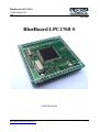
BlueBoard LPC1768-S
USER MANUAL
v1.0
1/07/2010
USB
The USB connector can also be used to powerup the board. In Windows XP it will be
detected as a Human Interface Device.
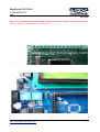
Test setup: Connect the USB cable to USB connector. The power LED (D14) and USB connect
LED (D10) turn ON.
VGA connector – code presently not available
Test setup: -- NA -JTAG connector
Test setup: To enable debugging on the board connect jumper to J11 and connect the JTAG to
debug port. We have successfully tested the BlueBoard with JTAG interface using a Wiggler Clone
JTAG. To test this feature you need to have the necessary software support on your PC. Also the
NGX USB JTAG can used with. Refer to the documentation here.
User Interface Switch
Test setup: The Switch SW1 is connected to one of the external interrupt lines of LPC. To test
this interface simply press the switch and you should hear the beep sound on the buzzer. This
confirms that both the interrupt line and the buzzer module are working fine. Please ensure that you
have connected the buzzer jumper appropriately.
Buzzer
Test setup: Connect jumper to J23, when the board is turned on or RESET you will hear a few
beeps. This is how the user can confirm the status of the Buzzer.
SD/MMC connector
Note: Do this test in the end as a new firmware has to be flashed and the previous test firmware will
be overwritten.
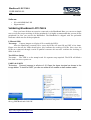
Test setup: To test the SD card a new firmware has to be loaded. This can be done using the Hhttp://shop.ngxtechnologies.com
8