1
UM0909
User manual
STM32W108xx ZigBee® RF4CE library
Introduction
This document describes the ST RF4CE library and how to use it to develop RF4CE
compliant applications on an STM32W device. It describes the RF4CE protocol as defined
by the ZigBee alliance and how the ST RF4CE library implements this protocol on STM32W
devices. This document applies to the following STM32W108xx kits:
●
STM32W108xx starter kit (part number: STM32W-SK)
●
STM32W108xx extension kit (part number: STM32W-EXT)
●
STM32W108xx low-cost RF control kit (part number: STM32W-RFCKIT)
A description on how to perform common RF4CE operations as well as certain architecturedependent operations is also included.
Finally, it describes reference applications for Target and Controller nodes as well as how to
use an STM32W device with the ST RF4CE library alongside an external microcontroller
(Coprocessor mode).
The ZigBee RF4CE library is designed to run on STM32W108 engineering samples and on
the STM32W108xBU63 microcontroller.
Table 1 lists the microcontrollers and tools concerned by this user manual.
Table 1.
Applicable products and tools
Type
August 2012
Part numbers/product sub-classes
Microcontrollers
STM32W108xx
Evaluation tools to MCUs
STM32W-SK
STM32W-EXT
STM32W-RFCKIT
Doc ID 17097 Rev 4
1/53
www.st.com
Contents
UM0909
Contents
1
2
RF4CE protocol description . . . . . . . . . . . . . . . . . . . . . . . . . . . . . . . . . . . 7
1.1
Overview . . . . . . . . . . . . . . . . . . . . . . . . . . . . . . . . . . . . . . . . . . . . . . . . . . 7
1.2
Network layer . . . . . . . . . . . . . . . . . . . . . . . . . . . . . . . . . . . . . . . . . . . . . . . 7
1.2.1
Node types . . . . . . . . . . . . . . . . . . . . . . . . . . . . . . . . . . . . . . . . . . . . . . . . 8
1.2.2
Network topology . . . . . . . . . . . . . . . . . . . . . . . . . . . . . . . . . . . . . . . . . . . 8
1.2.3
Frequency agility . . . . . . . . . . . . . . . . . . . . . . . . . . . . . . . . . . . . . . . . . . . 9
1.2.4
Discovery . . . . . . . . . . . . . . . . . . . . . . . . . . . . . . . . . . . . . . . . . . . . . . . . . 9
1.2.5
Pairing . . . . . . . . . . . . . . . . . . . . . . . . . . . . . . . . . . . . . . . . . . . . . . . . . . . 9
1.2.6
Message transmission and reception . . . . . . . . . . . . . . . . . . . . . . . . . . 10
1.2.7
Security . . . . . . . . . . . . . . . . . . . . . . . . . . . . . . . . . . . . . . . . . . . . . . . . . 10
1.2.8
Power-saving . . . . . . . . . . . . . . . . . . . . . . . . . . . . . . . . . . . . . . . . . . . . . 10
1.3
ZRC application profile . . . . . . . . . . . . . . . . . . . . . . . . . . . . . . . . . . . . . . . 11
1.4
ZID application profile . . . . . . . . . . . . . . . . . . . . . . . . . . . . . . . . . . . . . . . . 11
Using the STRF4CE API . . . . . . . . . . . . . . . . . . . . . . . . . . . . . . . . . . . . . 12
2.1
Programming model . . . . . . . . . . . . . . . . . . . . . . . . . . . . . . . . . . . . . . . . . 12
2.1.1
2.2
3
2/53
API to SAP mapping . . . . . . . . . . . . . . . . . . . . . . . . . . . . . . . . . . . . . . . 12
Initialization . . . . . . . . . . . . . . . . . . . . . . . . . . . . . . . . . . . . . . . . . . . . . . . . 13
2.2.1
Controller . . . . . . . . . . . . . . . . . . . . . . . . . . . . . . . . . . . . . . . . . . . . . . . . 13
2.2.2
Target . . . . . . . . . . . . . . . . . . . . . . . . . . . . . . . . . . . . . . . . . . . . . . . . . . . 13
2.3
Discovery . . . . . . . . . . . . . . . . . . . . . . . . . . . . . . . . . . . . . . . . . . . . . . . . . 14
2.4
Pairing . . . . . . . . . . . . . . . . . . . . . . . . . . . . . . . . . . . . . . . . . . . . . . . . . . . 14
2.5
Message exchanges . . . . . . . . . . . . . . . . . . . . . . . . . . . . . . . . . . . . . . . . 15
2.6
Security . . . . . . . . . . . . . . . . . . . . . . . . . . . . . . . . . . . . . . . . . . . . . . . . . . 16
2.7
Timer . . . . . . . . . . . . . . . . . . . . . . . . . . . . . . . . . . . . . . . . . . . . . . . . . . . . 16
2.8
Power consumption . . . . . . . . . . . . . . . . . . . . . . . . . . . . . . . . . . . . . . . . . 16
2.8.1
RF power-down . . . . . . . . . . . . . . . . . . . . . . . . . . . . . . . . . . . . . . . . . . . 16
2.8.2
SOC power down . . . . . . . . . . . . . . . . . . . . . . . . . . . . . . . . . . . . . . . . . . 16
2.8.3
RF standby . . . . . . . . . . . . . . . . . . . . . . . . . . . . . . . . . . . . . . . . . . . . . . 17
2.9
Non volatile memory management . . . . . . . . . . . . . . . . . . . . . . . . . . . . . . 17
2.10
RF4CE stack configuration . . . . . . . . . . . . . . . . . . . . . . . . . . . . . . . . . . . . 18
Designing an application using the RF4CE library . . . . . . . . . . . . . . . 20
Doc ID 17097 Rev 4
UM0909
4
Contents
ZRC demo application . . . . . . . . . . . . . . . . . . . . . . . . . . . . . . . . . . . . . . 22
4.1
Firmware common features . . . . . . . . . . . . . . . . . . . . . . . . . . . . . . . . . . . 22
4.2
Building the firmware . . . . . . . . . . . . . . . . . . . . . . . . . . . . . . . . . . . . . . . . 23
4.3
Programming the firmware . . . . . . . . . . . . . . . . . . . . . . . . . . . . . . . . . . . . 23
4.4
RS-232 remote control and target applications . . . . . . . . . . . . . . . . . . . . 23
4.5
ST Virtual RC and TV . . . . . . . . . . . . . . . . . . . . . . . . . . . . . . . . . . . . . . . . 27
4.6
5
6
7
4.5.1
ST Virtual RC . . . . . . . . . . . . . . . . . . . . . . . . . . . . . . . . . . . . . . . . . . . . . 28
4.5.2
ST Virtual TV . . . . . . . . . . . . . . . . . . . . . . . . . . . . . . . . . . . . . . . . . . . . . 30
ST Virtual RC and Sony Infrared TV (with an RF4CE I/R extender) . . . . 31
ZID demonstration application . . . . . . . . . . . . . . . . . . . . . . . . . . . . . . . . 32
5.1
IAR project . . . . . . . . . . . . . . . . . . . . . . . . . . . . . . . . . . . . . . . . . . . . . . . . 32
5.2
Jumper settings . . . . . . . . . . . . . . . . . . . . . . . . . . . . . . . . . . . . . . . . . . . . 32
5.3
Boards supported . . . . . . . . . . . . . . . . . . . . . . . . . . . . . . . . . . . . . . . . . . . 33
5.4
Serial I/O . . . . . . . . . . . . . . . . . . . . . . . . . . . . . . . . . . . . . . . . . . . . . . . . . 33
5.5
LED description . . . . . . . . . . . . . . . . . . . . . . . . . . . . . . . . . . . . . . . . . . . . 34
5.6
Buttons description . . . . . . . . . . . . . . . . . . . . . . . . . . . . . . . . . . . . . . . . . . 34
5.7
Usage . . . . . . . . . . . . . . . . . . . . . . . . . . . . . . . . . . . . . . . . . . . . . . . . . . . . 34
ZID, ZRC demonstration application . . . . . . . . . . . . . . . . . . . . . . . . . . . 36
6.1
IAR project . . . . . . . . . . . . . . . . . . . . . . . . . . . . . . . . . . . . . . . . . . . . . . . . 36
6.2
Jumper settings . . . . . . . . . . . . . . . . . . . . . . . . . . . . . . . . . . . . . . . . . . . . 37
6.3
Boards supported . . . . . . . . . . . . . . . . . . . . . . . . . . . . . . . . . . . . . . . . . . . 37
6.4
LED description . . . . . . . . . . . . . . . . . . . . . . . . . . . . . . . . . . . . . . . . . . . . 38
6.5
Button description . . . . . . . . . . . . . . . . . . . . . . . . . . . . . . . . . . . . . . . . . . 38
6.6
Set-up MEMS mouse device + RC platform . . . . . . . . . . . . . . . . . . . . . . . 38
6.7
Set up the HOST platform . . . . . . . . . . . . . . . . . . . . . . . . . . . . . . . . . . . . 39
6.8
How mouse and RC modes work . . . . . . . . . . . . . . . . . . . . . . . . . . . . . . . 39
Using the STRF4CE library in Coprocessor mode . . . . . . . . . . . . . . . . 41
7.1
7.2
Serial protocols . . . . . . . . . . . . . . . . . . . . . . . . . . . . . . . . . . . . . . . . . . . . 41
7.1.1
SPI protocol . . . . . . . . . . . . . . . . . . . . . . . . . . . . . . . . . . . . . . . . . . . . . . 41
7.1.2
UART protocol . . . . . . . . . . . . . . . . . . . . . . . . . . . . . . . . . . . . . . . . . . . . 42
Packet format . . . . . . . . . . . . . . . . . . . . . . . . . . . . . . . . . . . . . . . . . . . . . . 43
Doc ID 17097 Rev 4
3/53
Contents
UM0909
7.3
Serial RF4CE command codes . . . . . . . . . . . . . . . . . . . . . . . . . . . . . . . . 44
7.4
RF4CE serial communication code . . . . . . . . . . . . . . . . . . . . . . . . . . . . . 45
7.5
Physical level protocol . . . . . . . . . . . . . . . . . . . . . . . . . . . . . . . . . . . . . . . 46
7.6
Serial communication packet format example . . . . . . . . . . . . . . . . . . . . . 47
7.7
Software code structure . . . . . . . . . . . . . . . . . . . . . . . . . . . . . . . . . . . . . . 47
7.8
RF4CE network coprocessor demo . . . . . . . . . . . . . . . . . . . . . . . . . . . . . 49
7.8.1
Building the firmware . . . . . . . . . . . . . . . . . . . . . . . . . . . . . . . . . . . . . . . 49
7.8.2
Programming the firmware . . . . . . . . . . . . . . . . . . . . . . . . . . . . . . . . . . 49
7.8.3
Setting up the boards . . . . . . . . . . . . . . . . . . . . . . . . . . . . . . . . . . . . . . . 49
8
Reference documents . . . . . . . . . . . . . . . . . . . . . . . . . . . . . . . . . . . . . . . 50
9
Terms and definitions . . . . . . . . . . . . . . . . . . . . . . . . . . . . . . . . . . . . . . . 51
10
Revision history . . . . . . . . . . . . . . . . . . . . . . . . . . . . . . . . . . . . . . . . . . . 52
4/53
Doc ID 17097 Rev 4
UM0909
List of tables
List of tables
Table 1.
Table 2.
Table 3.
Table 4.
Table 5.
Table 6.
Table 7.
Table 8.
Table 9.
Table 10.
Table 11.
Table 12.
Table 13.
Table 14.
Table 15.
Table 16.
Table 17.
Table 18.
Table 19.
Table 20.
Table 21.
Table 22.
Table 23.
Applicable products and tools . . . . . . . . . . . . . . . . . . . . . . . . . . . . . . . . . . . . . . . . . . . . . . . . 1
API to SAP mapping . . . . . . . . . . . . . . . . . . . . . . . . . . . . . . . . . . . . . . . . . . . . . . . . . . . . . . 12
Configurable stack parameters . . . . . . . . . . . . . . . . . . . . . . . . . . . . . . . . . . . . . . . . . . . . . . 18
ZigBee RF4CE ZRC demo applications scenarios . . . . . . . . . . . . . . . . . . . . . . . . . . . . . . . 22
Firmware user interface . . . . . . . . . . . . . . . . . . . . . . . . . . . . . . . . . . . . . . . . . . . . . . . . . . . 22
RS-232 settings . . . . . . . . . . . . . . . . . . . . . . . . . . . . . . . . . . . . . . . . . . . . . . . . . . . . . . . . . 24
Firmware commands . . . . . . . . . . . . . . . . . . . . . . . . . . . . . . . . . . . . . . . . . . . . . . . . . . . . . 24
Button functions in ST Virtual RC . . . . . . . . . . . . . . . . . . . . . . . . . . . . . . . . . . . . . . . . . . . . 28
Jumper settings . . . . . . . . . . . . . . . . . . . . . . . . . . . . . . . . . . . . . . . . . . . . . . . . . . . . . . . . . 32
Boards supported . . . . . . . . . . . . . . . . . . . . . . . . . . . . . . . . . . . . . . . . . . . . . . . . . . . . . . . . 33
LED description . . . . . . . . . . . . . . . . . . . . . . . . . . . . . . . . . . . . . . . . . . . . . . . . . . . . . . . . . 34
Button description . . . . . . . . . . . . . . . . . . . . . . . . . . . . . . . . . . . . . . . . . . . . . . . . . . . . . . . . 34
Jumper settings . . . . . . . . . . . . . . . . . . . . . . . . . . . . . . . . . . . . . . . . . . . . . . . . . . . . . . . . . 37
Boards supported . . . . . . . . . . . . . . . . . . . . . . . . . . . . . . . . . . . . . . . . . . . . . . . . . . . . . . . . 37
LED description . . . . . . . . . . . . . . . . . . . . . . . . . . . . . . . . . . . . . . . . . . . . . . . . . . . . . . . . . 38
Button description . . . . . . . . . . . . . . . . . . . . . . . . . . . . . . . . . . . . . . . . . . . . . . . . . . . . . . . . 38
SPI signal and pin information . . . . . . . . . . . . . . . . . . . . . . . . . . . . . . . . . . . . . . . . . . . . . . 41
UART signal and pin information . . . . . . . . . . . . . . . . . . . . . . . . . . . . . . . . . . . . . . . . . . . . 42
RF4CE coprocessor command codes . . . . . . . . . . . . . . . . . . . . . . . . . . . . . . . . . . . . . . . . 44
Serial communication error codes . . . . . . . . . . . . . . . . . . . . . . . . . . . . . . . . . . . . . . . . . . . 45
Coprocessor board to MB525 connection with UART and SPI mode. . . . . . . . . . . . . . . . . 49
List of terms . . . . . . . . . . . . . . . . . . . . . . . . . . . . . . . . . . . . . . . . . . . . . . . . . . . . . . . . . . . . 51
Document revision history . . . . . . . . . . . . . . . . . . . . . . . . . . . . . . . . . . . . . . . . . . . . . . . . . 52
Doc ID 17097 Rev 4
5/53
List of figures
UM0909
List of figures
Figure 1.
Figure 2.
Figure 3.
Figure 4.
Figure 5.
Figure 6.
Figure 7.
Figure 8.
Figure 9.
Figure 10.
Figure 11.
Figure 12.
Figure 13.
Figure 14.
6/53
RF4CE stack overview . . . . . . . . . . . . . . . . . . . . . . . . . . . . . . . . . . . . . . . . . . . . . . . . . . . . . 7
RF4CE multi-PAN network . . . . . . . . . . . . . . . . . . . . . . . . . . . . . . . . . . . . . . . . . . . . . . . . . 8
Power saving scheme . . . . . . . . . . . . . . . . . . . . . . . . . . . . . . . . . . . . . . . . . . . . . . . . . . . . 11
RS-232 RC and target node . . . . . . . . . . . . . . . . . . . . . . . . . . . . . . . . . . . . . . . . . . . . . . . 24
RF4CE Virtual RC and TV . . . . . . . . . . . . . . . . . . . . . . . . . . . . . . . . . . . . . . . . . . . . . . . . . 27
ST Virtual RC . . . . . . . . . . . . . . . . . . . . . . . . . . . . . . . . . . . . . . . . . . . . . . . . . . . . . . . . . . . 29
ST Virtual TV screenshot . . . . . . . . . . . . . . . . . . . . . . . . . . . . . . . . . . . . . . . . . . . . . . . . . . 30
ST Virtual RC and Sony infrared TV . . . . . . . . . . . . . . . . . . . . . . . . . . . . . . . . . . . . . . . . . . 31
Host connection in SPI mode . . . . . . . . . . . . . . . . . . . . . . . . . . . . . . . . . . . . . . . . . . . . . . 42
Host connection in UART mode . . . . . . . . . . . . . . . . . . . . . . . . . . . . . . . . . . . . . . . . . . . . . 43
Packet format . . . . . . . . . . . . . . . . . . . . . . . . . . . . . . . . . . . . . . . . . . . . . . . . . . . . . . . . . . . 43
Serial communication started by the host (host side) . . . . . . . . . . . . . . . . . . . . . . . . . . . . 46
Serial communication started by the host (STM32W side) . . . . . . . . . . . . . . . . . . . . . . . . 46
Callback response (STM32W side) . . . . . . . . . . . . . . . . . . . . . . . . . . . . . . . . . . . . . . . . . . 46
Doc ID 17097 Rev 4
UM0909
RF4CE protocol description
1
RF4CE protocol description
1.1
Overview
The ZigBee® RF4CE standard was created by a consortium of companies with the
objective to deliver a standardized specification for RF-controlled home entertainment
products.
RF (radio frequency) remote controls are faster, more reliable and provide more freedom to
operate devices from greater distances by removing the line-of-sight barrier found in today's
IR (infrared) remote controls. They also enable advanced features such as two-way
communication between the device and the remote control, creating a richer experience for
consumers.
The RF4CE standard defines a network layer plus two application profiles for consumer
electronics ZRC and ZID. The following sections provide more details on the network layer
and the application profiles.
1.2
Network layer
The RF4CE network stack is a thin, flexible and future-proof layer with the following features:
●
Based on 2.4 GHz MAC/PHY IEEE 802.15.4 standard
●
Co-exists with other 2.4 GHz technologies
●
Support for interoperability
●
Support for secure communications
●
Powersave mechanisms implemented in network layer
●
Simple and intuitive pairing mechanism
●
Allow for vendor-specific applications and transactions
●
Support for many different applications
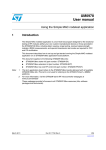
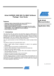
Figure 1 shows a layered representation of the RF4CE stack. For more details about the
network layer, please refer to [1].
Figure 1.
RF4CE stack overview
}
Application Layer
Profiles
Application Framework
Power Save
Topology
Security
Networking Layer
Channel Agility
MAC Layer
PHY Layer
Doc ID 17097 Rev 4
Management
Pairing
}
}
OEM
ZigBee RF4CE
Network and Profiles
IEEE 802.15.4
Ai15287
7/53
RF4CE protocol description
1.2.1
UM0909
Node types
The RF4CE standard defines only two node types with different roles:
●
●
1.2.2
Target Node with the following capabilities:
–
Network Startup
–
Full PAN capability
–
Accepts or declines a pairing request
–
Makes decision on operating channel (frequency agility)
Controller Node with the following capabilities:
–
Initiates pairing and discovery process with Target nodes
–
Implements frequency agility
–
On-demand communication
Network topology
ZigBee RF4CE PANs are essentially point-to-point or star topologies with a single node
acting as the target device and one or many nodes acting as remote controls. No routing is
allowed and communication happens between nodes within RF range.
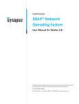
The ZigBee RF4CE network also supports multiple PANs and participation in multiple
networks (Figure 2).
Figure 2.
RF4CE multi-PAN network
Figure 2 illustrates an example ZigBee RF4CE topology which includes three target nodes:
a TV, a DVD and a CD player where each target node creates its own RC PAN. The TV, DVD
and CD player also have dedicated remote controls which are paired to each appropriate
target node. A multi-function remote control, capable of controlling all three target nodes
itself, is added to the network by successively pairing to the desired target nodes. The DVD
is also paired with the TV so that an external channel can be selected on the TV when a
DVD is played.
As a consequence, this remote control network consists of three separate remote control
PANs: one managed by the TV (PAN 1) containing the TV remote control, the multi-function
8/53
Doc ID 17097 Rev 4
UM0909
RF4CE protocol description
remote control and the DVD; a second managed by the CD player (PAN 2) containing the
CD remote control and the multi-function remote control and a third managed by the DVD
(PAN3) containing the DVD remote control, multi-function remote control and the TV.
1.2.3
Frequency agility
ZigBee RF4CE networks operate on the following IEEE 802.15.4 channels:
●
Channel 15: 2.425 GHz
●
Channel 20: 2.450 GHz
●
Channel 25: 2.475 GHz
Both target and controller node types support frequency agility.
Target nodes specify the PAN base frequency and can decide to switch frequencies on
adverse channel conditions. The detection of a channel busy condition is implementation
dependent.
Frequency reacquisition is achieved through a mechanism that allows other nodes by trying
each frequency and once found, the new channel information is stored for future
communications.
1.2.4
Discovery
The discovery procedure builds a list of devices in the “RF vicinity”.
Discovery requests are sent by the originating device (for example, a RC) and use a
broadcast, multi-channel service so that multiple devices can respond.
The discovery request also contains originator information to allow the device to respond.
When a discovery request is received, recipient devices normally inform the application of
the event. The application decides whether or not to respond to the discovery request.
The recipient device (for example, a television) sends a discovery response directly back to
the originator (for example, a RC) using a unicast service.
The discovery response contains recipient information.
When the discovery procedure is completed, originator devices inform the application of all
discovery information.
The application then decides whether to pair with a particular device.
1.2.5
Pairing
Pairing is a procedure required to establish a link between two devices in radio range that
wish to communicate.
Pairing is required prior to device communications and it is performed only once. Pairing
information is stored in non-volatile memory so that it can be retrieved after power cycling.
Pairing is similar to discovery where originator and recipient information is exchanged and
the application has full control of whether to accept or not.
Both originator and recipient devices create pairing table entries that contain addressing
information and security information, if applicable.
The application uses these entries via a reference index.
Doc ID 17097 Rev 4
9/53
RF4CE protocol description
1.2.6
UM0909
Message transmission and reception
Message exchanges are supported between paired devices only.
Transmission options include:
●
Acknowledged
–
●
–
●
Originator attempts transmission on the expected channel only
Multiple channel
–
●
Originator data is sent to all recipients
Single channel
–
●
Originator data is sent to a specific recipient
Broadcast
–
●
Originator data is not confirmed by the recipient
Unicast
–
●
Originator data is confirmed by the recipient
Unacknowledged
Originator attempts transmission using frequency re-acquisition mechanism
All data can be sent secured or unsecured
The options can be combined depending on the application, for example:
1.2.7
●
RCs typically use acknowledged, unicast and multiple channel options
●
Target devices typically use unacknowledged, unicast and single channel options
Security
Security is established when pairing nodes that support security in their node capabilities.
The security mechanism has the following features:
●
Utilizes AES-128 encryption
●
Security mode: ENC-MIC-32
●
Data confidentiality (via payload encryption)
●
Data authentication (via Message Integrity Code)
●
Replay protection (via frame counter)
●
Nodes use 128-bit link keys
●
Keys are generated automatically, if security is supported
●
Keys are stored in the pairing table
The application can decide which transmissions require the use of security.
1.2.8
Power-saving
The RF4CE specification defines a 2-state power-saving scheme: Active and Standby.
In normal use cases, RCs simply power off when no buttons are being pressed, while target
devices must also use power-saving techniques when in Standby.
Targets must also ensure a reasonable (human) reaction time to exit from Standby.
10/53
Doc ID 17097 Rev 4
UM0909
RF4CE protocol description
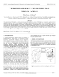
To achieve this, power-saving techniques use an active period during which the target
wakes up, and a duty cycle after which the device repeats the active period as shown in
Figure 3.
Figure 3.
1.3
Power saving scheme
ZRC application profile
The ZRC application profile is the first application profile defined for the RF4CE protocol. It
aims at replacing remote controls that use traditional infrared technology.
It defines a very simple push-button pairing process between the remote control and the
target device. The mechanism works in conjunction with existing ZigBee RF4CE discovery
and pairing mechanisms. Discovery, pairing and security (optional) all take place at a single
press of a button.
This application profile also defines a set of commands for basic CE device control, such as
remote control pressed, remote control repeated and remote control released.
Refer to Document [3] for a description of these embedded HDMI CEC commands.
The ZRC also provides support for manufacturer-specific commands.
1.4
ZID application profile
The ZID application profile is the second application profile defined for the RF4CE protocol.
It defines commands and procedures to enable devices such as mice, touchpads,
keyboards, wands, Riva wheels or RC pointers.
The RF4CE ZID profile defines the over-air commands and mechanisms required to allow a
Human interface device (HID) class device to communicate with a host. The profile defines
two types of device: a HID class device and a HID adaptor. The HID class device can be
used to support devices such as keyboards, mice or touchpads and the HID adaptor can be
used to communicate through a HID class driver to some PC or other embedded host.
Doc ID 17097 Rev 4
11/53
Using the STRF4CE API
UM0909
2
Using the STRF4CE API
2.1
Programming model
The STRF4CE library is a very efficient implementation based on a MAC/PHY layer
specifically tailored for RF4CE applications. It features a simple and efficient NVM
management system that stores non-volatile data and preserves the network layer state
using power cycling methods.
An RF4CE API also implements power management functions only for the radio part in
compliance with RF4CE specifications.
The same code base is used for both the target and controller node types.
The API is defined with a map close to the SAP defined in the specification.
The API is designed and implemented to be non-blocking; that is, the network layer
operations will give back control to the application when waiting for an event.
The core of an RF4CE compliant application is implemented through a never-ending loop
where the network layer state machine and application state machine are run.
while (1) {
/* Non blocking call to run the application state machine */
ApplicationTick();
/* Non blocking call to run the network layer state machine */
(void) NWK_Tick();
}
2.1.1
API to SAP mapping
The API provided by the STRF4CE library defines a set of functions that implement SAP
mapping according to Table 2. In the table, the term ‘F’ means that the SAP is implemented
as a function call, the term ‘RF’ means that the SAP is implemented as a function return
value and the term ‘C’ means that the SAP is implemented as a function callback called in
the context of NWK_Tick and is provided by the user.
Each API returns the following values:
●
SUCCESS: Operation completed successfully
●
RF4CE_SAP_PENDING: Operation started and pending; final result will be given by the
matching callback.
●
RF4CE_BUSY: Operation not started because the network layer is still performing some
other operation or the network layer has not been initialized.
●
Any other value: Error in the context of the specific operation.
Table 2.
API to SAP mapping
SAP
AUTO-DISC
Req
Conf
F
C
COMM-STATUS
12/53
Ind
Rsp
C
DISCOVERY
F
C
GET/SET
F
RF
Doc ID 17097 Rev 4
C
F
UM0909
Using the STRF4CE API
Table 2.
API to SAP mapping (continued)
SAP
2.2
Req
Conf
Ind
Rsp
PAIR
F
C
C
F
RESET
F
RF
RX-ENABLE
F
RF
START
F
C
UNPAIR
F
C
C
F
UPDATE-KEY
F
RF
DATA
F
C
C
Initialization
The network layer is initialized by calling the NWK_Init API. The NWK_Init API is used to
initialize the network layer according to the following parameters:
1.
nodeCap: the node capabilities as defined by RF4CE specifications.
2.
forceColdStart: If set to ‘True’, this boolean parameter allows the network layer to
perform a cold start (for example, the first startup outside the factory). Otherwise it will
perform a warm start, as defined by RF4CE specifications.
In normal use scenarios, the API should be called using the defined node capabilities and
with forceColdStart set to FALSE.
If there is a mismatch between the content of the NVM memory and the node capabilities,
the value RF4CE_NVM_DATA_INVALID is returned meaning that the NVM data contains
invalid data; in this case, an initialization with a forced cold start is required. This is normally
requested once when the device is first used outside the factory or in very special cases, but
not, for example, in the event of power loss (such as a battery replacement).
2.2.1
Controller
The controller is initialized immediately and its status is returned accordingly. If the call is
successful, the value ‘SUCCESS’ is returned and the network layer is ready for
communication. An example code for controller initialization is:
status = NWK_Init(0, FALSE);
if (status == RF4CE_NVM_DATA_INVALID) {
/* If warm start fails, try cold start */
status = NWK_Init(0, TRUE);
}
2.2.2
Target
The Network layer is initialized immediately in case of a warm start returning SUCCESS. In
case of a cold start, the API will return RF4CE_SAP_PENDING, meaning that network
initialization will be completed with the call of the user-defined callback
NLME_START_confirm. An example code for target initialization is:
void NLME_START_confirm (uint32_t *status)
{
Doc ID 17097 Rev 4
13/53
Using the STRF4CE API
UM0909
printf("RF4CE network started\r\n");
networkStarted = TRUE;
}
status = NWK_Init(1, FALSE);
if (status == RF4CE_NVM_DATA_INVALID) {
/* If warm start fails, try cold start */
status = NWK_Init(1, TRUE);
while (networkStarted == FALSE) {
(void) NWK_Tick();
}
}
2.3
Discovery
A device discovery operation is started either in a target or controller node with a call to the
NLME_DISCOVERY_request API with the appropriate parameters. In case of success, the
API returns the RF4CE_SAP_PENDING value and the discovery result is communicated
through the user-defined callback NLME_DISCOVERY_confirm.
Only target nodes are notified of device discoveries by the user-defined callback
NLME_DISCOVERY_indication. The target node can respond to a discovery indication
using a NLME_DISCOVERY_response API. In case of success, this API returns the
RF4CE_SAP_PENDING value and the discovery response status is communicated through
the user-defined callback COMM_STATUS_indication.
An example code for device discovery is:
uint32_t status;
NLME_DISCOVERY_REQUEST_Type param;
param.DstPANId = 0xFFFF;
param.DstNwkAddr = 0xFFFF;
param.OrgAppCapabilities = 0x12;
param.OrgDevTypeList[0] = 0x01;
param.OrgProfileIdList[0] = 0x01;
param.SearchDevType = 0xFF;
param.DiscProfileIdListSize = 0x01;
param.DiscProfileIdList = {0x01, 00};
param.DiscDuration = 0x0016e36;
status = NLME_DISCOVERY_request (¶m);
2.4
Pairing
Device pairing is required prior to starting any communication with an RF4CE node. Device
pairing can be started either in a target or controller node with a call to the
NLME_PAIR_request API with the appropriate parameters. In case of success, the API
14/53
Doc ID 17097 Rev 4
UM0909
Using the STRF4CE API
returns RF4CE_SAP_PENDING and a pairing operation result is communicated through the
callback NLME_PAIR_confirm.
The target node can respond to a pair indication using an NLME_PAIR_response API. In
case of success, this API returns the value RF4CE_SAP_PENDING and the pair response
status is communicated through the user-defined callback COMM_STATUS_indication.
An example code for device pairing is:
uint32_t status;
NLME_PAIR_REQUEST_Type param;
IEEEAddr dstLongAddr = {0x00, 0x11, 0x22, 0x33, 0x44, 0x55, 0x66, 0x77};
param.LogicalChannel = 15;
param.DstPANId = 0x1234;
memcpy(param.DstIEEEAddr, dstLongAddr, sizeof(IEEEAddr));
param.OrgAppCapabilities = 0x13;
param.OrgDevTypeList[0] = 0x01;
param.OrgProfileIdList[0] =
0x01;
param.KeyExTransferCount = 3;
status = NLME_PAIR_request(¶m);
2.5
Message exchanges
Messages are transmitted through the use of the NLDE_DATA_request and can be sent by
both a controller node and a target node. The RF4CE standard states that the following
types of communication are possible:
●
Controller to target
●
Target to controller
●
Target to target
Messages can be exchanged only between nodes that have previously been paired; that is,
a valid pairing entry exists in the pairing table.
In case of success, the API returns RF4CE_SAP_PENDING and the message transmission
result is communicated through the call of NLDE_DATA_confirm. Any other value returned
by the API should be considered as an error condition.
Message reception is indicated to the user application through the user-defined callback
NLDE_DATA_indication.
An example message exchange is:
uint32_t status;
NLDE_DATA_REQUEST_Type param;
param.nsduLength = 1;
param.nsdu[0] = 0x11;
param.PairingRef = 0;
param.ProfileId = 0x01; //Consumer Electronics Remote control
param.VendorId = 0xfff1; //Test vendor id #1
param.TxOptions = 0x4c; // Unicast - nwk address - ack - security -
Doc ID 17097 Rev 4
15/53
Using the STRF4CE API
UM0909
// multiple channel - no channel designator
// - vendor specific
status = NLDE_DATA_request(¶m);
2.6
Security
The security is automatically activated by the stack when the node capabilities of paired
nodes show that the node supports security (see nodeCap parameters in Section 2.2).
Even if the security is enabled over a couple of paired nodes, the application has still the
ability to select between secure and non-secure communications when using the
NLDE_DATA_request API. If the security is not enabled, only non-secure communications
are allowed.
2.7
Timer
A simple timer API is used by the stack to handle timeouts and delays. The timer has a
resolution of 1 µs.
An application can use both API TIME_CurrentTime and TIME_ELAPSED timers.
2.8
Power consumption
The stack contains a built-in mechanism to support power-saving schemes.
2.8.1
RF power-down
The power-down of the RF part is achieved through a call to NLME_RX_ENABLE_request
with RxOnDuration parameters set to 0.
The stack confirms the power-down of the RF part when the NWK_Tick API return value
has the bit RF4CE_STATE_POWER_DOWN set.
An example code for RF power-down is:
NLME_RX_ENABLE_request(0);
while ((NWK_Tick() & RF4CE_STATE_POWER_DOWN) == 0);
A helper function NWK_PowerDown() is provided to implement the above code and its use
is recommended.
The stack can be brought back to normal operation with a call to
NLME_RX_ENABLE_request with RxOnDuration parameters set to 0xFFFFFF or using
the helper function NWK_PowerUp(FALSE).
2.8.2
SOC power down
For a maximum battery life in real-life applications, it could be useful to shut down the entire
SOC. In this case, the sequence of operations should be as follows:
NWK_PowerDown();
ATOMIC(
/* Configure RX, TX pins to achieve minimum power consumption on MB851 */
16/53
Doc ID 17097 Rev 4
UM0909
Using the STRF4CE API
GPIOB->ODR &= ~((1 << 1) | (1 << 2));
halGpioConfig(PORTB_PIN(1), GPIO_Mode_IN_PUD);
halGpioConfig(PORTB_PIN(2), GPIO_Mode_IN_PUD);
halPowerDown();
halSleepWithOptions(SLEEPMODE_NOTIMER,
BUTTON_S1_WAKE_SOURCE|UART_RX_WAKE_SOURCE | 0x20); //DeepSleep 2; 0x20 is
to keep happy Primer 2
halPowerUp();
);
NWK_PowerUp(TRUE);
uartInit();
2.8.3
RF standby
RF4CE specifications define a mechanism used to reduce the power consumption using the
NLME_RX_ENABLE_request function with parameter RxOnDuration set to
nwkActivePeriod. A simple piece of code to activate standby is shown below:
{
uint32_t activePeriod;
NLME_Get (nwkActivePeriod_ID, 0, &activePeriod);
NLME_RX_ENABLE_request(activePeriod);
}
2.9
Non volatile memory management
The ST RF4CE stack contains a module used to manage NVM storage using 1 Kbyte of
Flash memory. NVM usage is transparent to the user, but some interaction with the
application is required to limit Flash wearing.
Flash wearing is limited using a cache of the NVM data in RAM. This cache needs to be
flushed into the actual flash periodically, so that it is not lost in case of a power failure. The
following code provides an example of how to flush the NVM cache:
retVal = NWK_Tick();
/* Check whether cache flush is required */
if (retVal & RF4CE_STATE_NEED_CACHE_FLUSH) {
NWK_Flush();
}
The NWK_Tick return value gives an indication when cache and NVM are not consistent.
A call to NWK_Flush() is not mandatory and can be delayed if necessary since the
NWK_Flush operation requires about 40 ms to complete. The application can choose when
it is more appropriate to call it and how often.
Doc ID 17097 Rev 4
17/53
Using the STRF4CE API
2.10
UM0909
RF4CE stack configuration
The ST RF4CE library allows the configuration of certain stack parameters at run time.
These stack parameters (Table 3) are, according to the specification, constants but
implementation-dependent.
Table 3.
Configurable stack parameters
Valid range
Default
value
nwkcMaxNodeDescListSize
Not specified
3
Not changeable without
recompiling the stack.
nwkcMaxPairingTableEntries
Not specified
5
Not changeable without
recompiling the stack.
nwkcNodeCapabilities
Not specified
N/A
Do not change this, but use
NWK_Init to set the node
capabilities.
nwkcVendorIdentifier
16 bit value
0xFFF1
Vendor ID, please use
NWK_Config to change it.
7-character string
“ST”
Vendor string, please use
NWK_Config to change it.
Name
nwkcVendorString
Description
For a complete description of the parameters, please refer to documents [1], [2] and [6].
The stack configuration is required prior to cold starting the stack using NWK_Init; it is
stored in the non volatile memory.
The following code shows how to configure the stack using NWK_Config:
void NLME_START_confirm (uint32_t *status)
{
printf("RF4CE network started\r\n");
networkStarted = TRUE;
}
status = NWK_Init(0, FALSE);
if (status == RF4CE_NVM_DATA_INVALID) {
/* If warm start fails, try cold start */
uint16_t myVendorId = 0xabcd;
NWK_Config(nwkcVendorIdentifier_ID, &myVendorId);
NWK_Config(nwkcVendorString_ID, "Vendor");
status = NWK_Init(1, TRUE);
while (networkStarted == FALSE) {
(void) NWK_Tick();
}
}
All other network parameters can be modified using the NLME_Set API.
Below is an example of how to set up the nwkUserString parameter. This should be done
only once after a cold start.
NLME_SET_Type val;
18/53
Doc ID 17097 Rev 4
UM0909
Using the STRF4CE API
val.NIBAttribute = nwkUserString_ID;
val.NIBAttributeIndex = 0;
val.NIBAttributeValue = "STM32W Target";
Doc ID 17097 Rev 4
19/53
Designing an application using the RF4CE library
3
UM0909
Designing an application using the RF4CE library
The code below shows a skeleton application for implementing an RF4CE target device.
#include "rf4ce.h"
void NLDE_DATA_confirm(NLDE_DATA_CONFIRM_Type *param)
{
< Your code here >;
}
void NLME_START_confirm(uint32_t *status)
{
printf("RF4CE network started\r\n");
networkStarted = TRUE;
}
void NLME_AUTO_DISCOVERY_confirm(NLME_AUTO_DISCOVERY_CONFIRM_Type
*param)
{
< Your code here >;
}
void NLME_DISCOVERY_confirm (NLME_DISCOVERY_CONFIRM_Type *param)
{
< Your code here >;
}
void NLME_PAIR_confirm(NLME_PAIR_CONFIRM_Type *params)
{
< Your code here >;
}
void NLME_UNPAIR_confirm(NLME_UNPAIR_CONFIRM_Type *param)
{
< Your code here >;
}
void NLDE_DATA_indication(NLDE_DATA_INDICATION_Type *param);
{
< Your code here >;
}
void NLME_DISCOVERY_indication(NLME_DISCOVERY_INDICATION_Type *param)
{
< Your code here >;
}
void NLME_PAIR_indication (NLME_PAIR_INDICATION_Type *params)
{
< Your code here >;
}
void NLME_COMM_STATUS_indication (NLME_COMM_STATUS_INDICATION_Type *params)
{
20/53
Doc ID 17097 Rev 4
UM0909
Designing an application using the RF4CE library
< Your code here >;
}
void NLME_UNPAIR_indication (uint8_t *PairingRef)
{
< Your code here >;
}
int main (void)
{
/* Initialization phase */
........
/* init serial */
/* Initialize serial interface */
................
status = NWK_Init(1, FALSE);
if (status == RF4CE_NVM_DATA_INVALID) {
/* If warm start fails, try cold start */
uint16_t myVendorId = 0xabcd;
NWK_Config(nwkcVendorIdentifier_ID, &myVendorId);
NWK_Config(nwkcVendorString_ID, "Vendor");
status = NWK_Init(1, TRUE);
while (networkStarted == FALSE) {
(void) NWK_Tick();
}
}
while (1) {
/* Non blocking call to advance application state machine */
ApplicationTick();
/* Non blocking call to advance network layer state machine */
(void) NWK_Tick();
}
}
Doc ID 17097 Rev 4
21/53
ZRC demo application
4
UM0909
ZRC demo application
The ZigBee RF4CE demo applications target the ZigBee RF4CE ZRC (Consumer electronic
remote control) profile for remote control and target devices for the scenarios listed in
Table 4.
Table 4.
ZigBee RF4CE ZRC demo applications scenarios
RF4CE remote control
RF4CE target device
RS232 RC
RS232 Target
ST Virtual RC
ST Virtual TV
ST Virtual RC
Sony infrared TV
All combinations between RCs and targets are supported.
These scenarios demonstrate simple RF4CE interactions between an RC and a target
device with:
●
Discovery and pairing
●
Secure communications
●
Data transmission
●
Power management
The STM32W108 RF4CE ZRC firmware is the same in both RC and target devices and can
be used in different scenarios according to Section 4.4: RS-232 remote control and target
applications, Section 4.5: ST Virtual RC and TV and Section 4.6: ST Virtual RC and Sony
Infrared TV (with an RF4CE I/R extender).
This firmware can also be considered as a reference application for customers who want to
implement a ZRC profile on top of the ZigBee RF4CE stack.
4.1
Firmware common features
The RF4CE ZRC firmware provides a user interface, through an RS-232 interface, with
LEDs and push-buttons. When loaded on any board, the firmware user interactions are
those described in Table 5.
Table 5.
Firmware user interface
User interface item
22/53
Direction
RS-232 via USB
Input/Output
LED D3 (Yellow)
Output
Description
Command line interface (see Section 4.4)
Heartbeat LED should be flashing at all times, except when
in Standby.
Doc ID 17097 Rev 4
UM0909
ZRC demo application
Table 5.
Firmware user interface (continued)
User interface item
Direction
Description
ON: RF4CE network initialized as target.
OFF: RF4CE network layer not initialized or initialized as
remote control.
LED D1 (Green)
Output
Blinks every sec:
RF4CE network layer cold start in progress.
Blinks every 0.2 sec:
RF4CE target node waiting for pairing from remote control.
LED D1 OFF: Press to start the node as a target.
Push-button S1
Input
LED D1 ON: Press to enable pairing.
LED D1 ON: Press for more than 2 seconds to bring the
RF4CE node to unconfigured state.
The following subsection provides a description of the building and running steps of the
demonstration applications using the IAR projects delivered within the RF4CE software
library package as a reference. The available workspaces provide reference examples for
the STM32W108CC boards.
4.2
Building the firmware
The firmware can be built from the IAR Embedded Workbench sources using the related
IAR project file.
4.3
Programming the firmware
The firmware can be programmed in the boards using the IAR Embedded Workbench or
using the stm32w_flasher utility.
For information on how to use the stm32w_flasher utility, refer to the STM32W-SK and
STM32W-EXT starter and extension kits for STM32W108xx user manual (reference:
UM0894).
4.4
RS-232 remote control and target applications
In this demo scenario, the user interacts with the boards using a PC HyperTerminal and the
user can set a node as an RF4CE target or as an RF4CE controller (Figure 4).
This demo scenario uses two boards and it can be run even on a single PC.
The RS-232 port in the PC should be set according to the values shown in Table 6.
Doc ID 17097 Rev 4
23/53
ZRC demo application
Table 6.
UM0909
RS-232 settings
Parameter
Setting
Baud rate
115200
Data bits
8
Parity
None
Stop bits
1
Flow control
Figure 4.
Xon/Xoff
RS-232 RC and target node
The demo supports the commands (case-sensitive) as shown in Table 7 over the
HyperTerminal. (The two devices are named #1 and #2 in reference to the STM32W108
boards and are both loaded with the rf4ce firmware image.)
Table 7.
Firmware commands
Command
24/53
Description
T
Configure the node as the target
C
Configure the node as the controller
D
Discovery & pair procedure
Z
Discovery & pair procedure from a target
p
Dump pairing table
R
Device software reset
e
Clear pairing table
E
Erase the NVM storage
S
Enable the power save
A
Disable the power save
O
Update the remote control firmware over the air from the target. (The
firmware sent is the target Flash image).
Note: the remote control and the target should contain the bootloader code
(iap_bootloader.s37) at the bottom of the Flash memory space.
?
Print Help menu
+
Send command key (pressed): volume up
-
Send command key (pressed): volume down
>
Send command key (pressed): channel up
<
Send command key (pressed): channel down
Doc ID 17097 Rev 4
UM0909
ZRC demo application
Table 7.
Firmware commands (continued)
Command
Description
0-9
Send command key (pressed): channel 0-9
ESC
Enter the string command mode
To run the demo applications, type the following command sequences:
1.
#1, #2: If the devices are not configured, the prompt is: “Unconfig>”. Otherwise type E
to cancel any previous configuration.
2.
#1: Type command T to configure the target. Wait approximately 5 seconds to end the
RF4CE network initialization. If the initialization is correct, the prompt will be:
Target(-1)> (-1 indicates that the device is not paired).
3.
#2: Type command C to configure the controller (remote control). If the initialization is
correct, the prompt is: Controller(-1)> (-1 indicates that the device is not paired).
4.
#1, #2: Type command D and wait for the confirm messages on both boards.
Below is an example of a log of discovery and pair messages with status OK:
CONTROLLER:
Controller(-1)>D
<CERC_DSC_PAIR>
Status = 00000100
<CERC_DSC_PAIR_END>
Controller(-1)><CERC_PAIR_CONFIRM>
Status = 00000000
PairingRef = 00
VendorId = FFF2
VendorString = Vendor
AppCapabilities = 13
UserString = STM32W Target
DevTypeList = 02
<CERC_PAIR_CONFIRM_END>
Controller(0)>
TARGET:
Target(-1)>D
<CERC_DSC_PAIR>
Status = 00000100
<CERC_DSC_PAIR_END>
Target(-1)><CERC_PAIR_INDICATION>
Status = 00000000
PairingRef = 00
VendorId = FFF1
VendorString = ST
AppCapabilities = 13
UserString = STM32W RC
DevTypeList = 01
Doc ID 17097 Rev 4
25/53
ZRC demo application
UM0909
PANId = FFFF
Address = 0080E1020000026C
<CERC_PAIR_INDICATION_END>
<CERC_RF4CE_COMM_STATUS_INDICATION>
Status = 00000000
PairingRef = 00
PANId = FFFF
Address = 0080E1020000026C
<CERC_RF4CE_COMM_STATUS_INDICATION_END>
Target(0)>
Furthermore, you can verify that the pairing operation is successful by checking the pairing
table contents.
#1, #2: Type the command p to verify that the devices are paired.
You can find below an example of the device paired. The status must be 0x02; otherwise,
the discovery and pair procedure has failed for some reason.
Controller(0)>p
<CERC_PAIRING_TABLE>
c status sNWK CH dstIEEEAddr
dPAN dNWK frmcnt
cp linkKey
0 02
A645 19 0080E10200000261 72FA E596 00000409 07
76ECD8D2C68C71800069D9B91B3667A7
1 FF
FFFF FF FFFFFFFFFFFFFFFF FFFF FFFF FFFFFFFF FF
FFFFFFFFFFFFFFFFFFFFFFFFFFFFFFFF
2 FF
FFFF FF FFFFFFFFFFFFFFFF FFFF FFFF FFFFFFFF FF
FFFFFFFFFFFFFFFFFFFFFFFFFFFFFFFF
3 FF
FFFF FF FFFFFFFFFFFFFFFF FFFF FFFF FFFFFFFF FF
FFFFFFFFFFFFFFFFFFFFFFFFFFFFFFFF
4 FF
FFFF FF FFFFFFFFFFFFFFFF FFFF FFFF FFFFFFFF FF
FFFFFFFFFFFFFFFFFFFFFFFFFFFFFFFF
You can now press keys on the controller and check that they are correctly received by the
target.
1.
2.
#2 (remote control). Type commands:
–
Change channel keys 0-9
–
Volume up +
–
Volume down -
–
Channel up >
–
Channel down <
#1 (target). For each key pressed and released, it receives two packets:
a)
One with payload 0x01 (KEY_PRESSED) and containing an hex number 0x##
according to the following list:
KEY_PRESSED plus
0x20 = “Channel 0” -0x29 = “Channel 9”
0x41 = “VolUp”
0x42 = “VolDown”
26/53
Doc ID 17097 Rev 4
UM0909
ZRC demo application
0x30 = “ChannelUp”
0x31 = “ChannelDown”
b)
One with payload 0x03 (KEY_RELEASED).
If you keep the key pressed, the ZRC profile sends a packet with payload 0x02 to indicate
that the key is being repeated.
Note:
For each key received, the infrared LED in the target emits a Sony RC compatible
sequence. This is useful for driving a Sony TV with an infrared remote control.
4.5
ST Virtual RC and TV
This demo scenario uses two boards and two PC applets to emulate an RF4CE remote
control and an RF4CE TV (see Figure 5).
The ST Virtual RC is a PC applet implementing a remote control driven through a PC GUI.
The ST Virtual TV is a PC applet implementing a TV driven through a PC GUI.
To start the demo, please make sure you have two boards connected to the PC through the
USB port and perform the following steps:
Note:
1.
Run the ST Virtual RC and ST Virtual TV applications from the PCApplet folder.
2.
On the Virtual RC application, select a serial port from the drop-down menu. (If the
firmware is not present in the board, it will be automatically downloaded by the
application.) Wait for the initialization procedure to complete (“ST RF4CE RC Ready”
message is displayed).
3.
On the Virtual TV application, select a serial port from the drop-down menu. (If the
firmware is not present in the board, it will be automatically downloaded by the
application.) Wait for the initialization procedure to complete (“ST RF4CE TV Ready”
message is displayed).
4.
On the Virtual RC application, select
to start the pairing procedure.
5.
On the Virtual TV application, select
to start the pairing procedure.
6.
If everything is OK, the message “Paired” is displayed on the TV and a confirmation
message with technical details is displayed on the RC after a few seconds.
7.
The demo is now operational and the key presses on the virtual RC will perform the
requested action on the virtual TV as specified in Table 8.
If you run again the demo with the same boards as RC and TV, the devices are already
paired and steps 4, 5 and 6 are not necessary.
Figure 5.
RF4CE Virtual RC and TV
Doc ID 17097 Rev 4
27/53
ZRC demo application
4.5.1
UM0909
ST Virtual RC
The ST Virtual RC is a PC GUI application that emulates an RF4CE RC and supports the
commands listed in Table 8.
Table 8.
Button functions in ST Virtual RC
Key label
0-9
28/53
ZRC code
Infrared code
0x43
0x14
Mute button
0x41
0x12
Volume up button
0x42
0x13
Volume down button
0x40
0x15
Standby button
0x30
0x10
Channel up button
0x31
0x11
Channel down button
0x44
0x1A
Play button
0x46
0x19
Pause button
0x69
0x25
AV button
0x20-0x29
0x09, 0x010x08
Digit button
0x35
0x3A
Info button
0x09
0x60
Menu button
0x01
0x74
Up button
0x02
0x75
Down button
0x04
0x33
Right button
0x03
0x34
Left button
0x00
0x65
Select/OK button
N/A
N/A
Cancel all paired devices
Doc ID 17097 Rev 4
Description
UM0909
ZRC demo application
Table 8.
Button functions in ST Virtual RC (continued)
Key label
ZRC code
Infrared code
Description
N/A
N/A
Show the list of paired devices
N/A
N/A
Search and pair RF4CE target
Figure 6 shows a snapshot of the ST Virtual RC application.
Figure 6.
ST Virtual RC
Doc ID 17097 Rev 4
29/53
ZRC demo application
4.5.2
UM0909
ST Virtual TV
The ST Virtual TV is a PC GUI application that emulates an RF4CE TV and supports the
following features:
●
12 channels, playing video from files
●
Volume control
●
Mute
●
Channel change
●
Play/Pause
●
Pair button
●
Erase pairing table button
●
Paired devices information
Figure 7.
30/53
ST Virtual TV screenshot
Doc ID 17097 Rev 4
UM0909
4.6
ZRC demo application
ST Virtual RC and Sony Infrared TV (with an RF4CE I/R
extender)
This demo scenario targets a demo and an infrared TV supporting Sony codes (see
Figure 8).
The RF4CE I/R extender is an STM32W108 MB851/MB954 board which acts as an RF4CEInfrared bridge between the ST Virtual RF4CE RC and a Sony TV. Please note that:
●
rf4ce firmware is requested to be loaded in the STM32W108 MB851/MB954 board
●
Jumper JP1 should be fitted
The Sony infrared TV is a normal TV supporting Sony I/R codes as listed in Table 8 with the
MB851/MB954 board placed close to the infrared receiver.
Figure 8.
ST Virtual RC and Sony infrared TV
MB851 I/R
extender
Sony I/R TV
ST Virtual RC
The ST RF4CE I/R extender supports the following features:
Note:
●
Network layer cold start by pressing button S1 when LED D1 is off.
●
Pairing mode when LED D1 is on by pressing button S1.
●
Erase pairing table and bring to the unconfigured state when pressing button S1 for
more than 2 seconds.
This demo can also run using the STM32-Primer2 with MB850 available only with the
STM32W108B-SK kit (boards with STM32W108CB devices).
Doc ID 17097 Rev 4
31/53
ZID demonstration application
5
UM0909
ZID demonstration application
This is a mouse demonstration application, based on the RF4CE ZID application profile.
Warning:
5.1
THIS APPLICATION SOFTWARE IS PROVIDED FOR
INTERNAL DEMONSTRATION PURPOSE ONLY AND NO
OTHER USE IS PERMITTED. THIS APPLICATION IS
PROVIDED ON AN "AS IS" BASIS, WITHOUT WARRANTY OF
ANY KIND, EITHER STATUTORY, EXPRESS OR IMPLIED,
INCLUDING WITHOUT LIMITATION, WARRANTIES OF TITLE,
NON-INFRINGEMENT, MERCHANTABILITY, SATISFACTORY
QUALITY AND FITNESS FOR A PARTICULAR PURPOSE.
WITHOUT LIMITING THE GENERALITY OF THE FOREGOING,
ST EXPRESSLY DOES NOT WARRANT THE ACCURACY,
SAFETY, OR USEFULNESS FOR ANY PURPOSE, OF THE
SOFTWARE APPLICATION.
ST HEREBY DISCLAIMS, TO THE FULLEST EXTENT
PERMITTED BY APPLICABLE MANDATORY LAW, ANY AND
ALL LIABILITY FOR THE USE OF THE SOFTWARE
APPLICATION, INCLUDING BUT NOT LIMITED TO ANY
LIABILITY IN CONTRACT, TORT, OR OTHERWISE,
WHATEVER THE CAUSE THEREOF, LIABILITY FOR ANY
LOSS OF PROFIT, BUSINESS OR GOODWILL OR ANY
DIRECT, INDIRECT, SPECIAL, CONSEQUENTIAL,
INCIDENTAL OR PUNITIVE COST, DAMAGES OR EXPENSE
OF ANY KIND, HOWSOEVER ARISING UNDER OR IN
CONNECTION WITH THIS USE.
IAR project
There is a single firmware image to perform the roles of mouse and dongle. The mouse is
the device acting as MEMS based mouse device which sends ZID RF4CE messages to the
dongle. The dongle is one of the supported ST boards connected to PC via USB and acting
as an RF4CE ZID Host adapter. The firmware is not configured initially and users can
configure it using button press combinations (see Table 12: Button description).
5.2
Jumper settings
Table 9.
Jumper settings
Jumper name
JP1, if available
32/53
Role
STM32W108
MOUSE
Fitted
DONGLE
Does not matter
MOUSE, DONGLE
1-2 (battery) 5-6 (USB)
Doc ID 17097 Rev 4
UM0909
5.3
ZID demonstration application
Boards supported
Table 10.
Boards supported
Board name
Board revision
Role
STM32W108xB
STM32W108CC
A,B
MOUSE
X
NA
A,B
DONGLE
-
NA
C
MOUSE, DONGLE
X
NA
D
MOUSE, DONGLE
NA
X
A
MOUSE
X
NA
A
DONGLE
-
NA
B
MOUSE, DONGLE
X
NA
C
MOUSE, DONGLE
NA
X
MB953A
MOUSE, DONGLE
X
NA
MB953B
MOUSE, DONGLE
NA
X
A
MOUSE
-
NA
A
DONGLE
X
NA
B
MOUSE
NA
-
B
DONGLE
NA
X
MB851
MB954
MB950A + MB953
MB951
X = supported
- = not supported
NA = not applicable
5.4
Serial I/O
Debug info only in case of errors.
Doc ID 17097 Rev 4
33/53
ZID demonstration application
5.5
UM0909
LED description
Table 11.
LED description
LED
Role
STM32W108
OFF
Blinks twice if configured as a mouse.
NONE
D1
D3
5.6
MOUSE
ON only when an RF transmission is taking place.
Blinks every 0.1 second while pairing.
Blinks twice if the configuration is deleted.
DONGLE
ON during normal operation.
Blinks every 0.5 seconds while network startup.
Blinks every 0.1 second while pairing.
MOUSE, DONGLE
Flashing.
OFF when in deep sleep.
Buttons description
Table 12.
Button description
Button
Role
Paired
STM32W108
NONE
N/A
If held down while resetting for less than 5
seconds, configured as a mouse.
If pressed after reset, configured as dongle.
MOUSE
No
If held down while resetting for more than
5 seconds, delete configuration as mouse.
If pressed, start pairing.
MOUSE
Yes
If held down while resetting for more than
5 seconds, delete configuration as mouse.
If pressed left click, wakeup.
DONGLE
Does not matter
If pressed for more than 2 seconds, reset
pairing table.
If pressed shortly, start pairing.
S2, if available
MOUSE
Yes
Left click, wakeup
S3, if available
MOUSE
Yes
Right click, wakeup
S4, if available
MOUSE
Yes
Right click, wakeup
S5, if available
MOUSE
Yes
Wakeup
S1
5.7
Usage
The RF4CE ZID demo is based on the application profile version 0.9 (08 March 2011). It
demonstrates the basic steps to configure two boards, one as a HID device and the other as
a HID USB adaptor. The HID device is a mouse, which is based on the detection of the
MEMS axis accelerations that translate to mouse movements and are sent to the receiver
attached to the PC. Please flash the supported boards with hid_rf4ce image. To start up the
demo, follow the steps below:
34/53
Doc ID 17097 Rev 4
UM0909
ZID demonstration application
1.
Connect the HID USB dongle to the PC and press the S1 button. The LED D1 blinks
every half second for ~5 sec. If the configuration is OK, the LED D1 at the end is ON.
2.
Configure the HID mouse device (by resetting the board by keeping the S1 button
pressed for less than 5 seconds).
3.
Start the pairing procedure by pressing the S1 button on both boards. LED D1 blinks
every 100 msec until the pairing procedure ends.
Both boards are now configured and paired and you should be able to use the mouse
transmitter as a mouse for your PC. Tilt the mouse transmitter in a direction and the speed
of the mouse is proportional to the tilt angle.
●
Tilting towards the ground will move the mouse down
●
Tilting towards the ceiling will move the mouse up
●
Tilting left will move the mouse left
●
Tilting right will move the mouse right
The ZID RF4CE demo puts the mouse device in deep sleep after 5 seconds of inactivity. To
wake up the mouse, push any button.
Doc ID 17097 Rev 4
35/53
ZID, ZRC demonstration application
6
UM0909
ZID, ZRC demonstration application
This is a demonstration application, based on the RF4CE ZRC & ZID application profile. It
shows the coexistence between the two ZigBee RF4CE ZRC and ZID application profiles.
Warning:
6.1
THIS APPLICATION SOFTWARE IS PROVIDED FOR
INTERNAL DEMONSTRATION PURPOSE ONLY AND NO
OTHER USE IS PERMITTED. THIS APPLICATION IS
PROVIDED ON AN "AS IS" BASIS, WITHOUT WARRANTY OF
ANY KIND, EITHER STATUTORY, EXPRESS OR IMPLIED,
INCLUDING WITHOUT LIMITATION, WARRANTIES OF TITLE,
NON-INFRINGEMENT, MERCHANTABILITY, SATISFACTORY
QUALITY AND FITNESS FOR A PARTICULAR PURPOSE.
WITHOUT LIMITING THE GENERALITY OF THE FOREGOING,
ST EXPRESSLY DOES NOT WARRANT THE ACCURACY,
SAFETY, OR USEFULNESS FOR ANY PURPOSE, OF THE
SOFTWARE APPLICATION.
ST HEREBY DISCLAIMS, TO THE FULLEST EXTENT
PERMITTED BY APPLICABLE MANDATORY LAW, ANY AND
ALL LIABILITY FOR THE USE OF THE SOFTWARE
APPLICATION, INCLUDING BUT NOT LIMITED TO ANY
LIABILITY IN CONTRACT, TORT, OR OTHERWISE,
WHATEVER THE CAUSE THEREOF, LIABILITY FOR ANY
LOSS OF PROFIT, BUSINESS OR GOODWILL OR ANY
DIRECT, INDIRECT, SPECIAL, CONSEQUENTIAL,
INCIDENTAL OR PUNITIVE COST, DAMAGES OR EXPENSE
OF ANY KIND, HOWSOEVER ARISING UNDER OR IN
CONNECTION WITH THIS USE.
IAR project
This demonstration application shows the RF4CE ZID and ZRC application profile merged
features, by using an HID device and a ZRC remote control. It requires 2 platforms:
●
one configured as ZID RF4CE MEMS mouse device and ZRC
●
one configured as USB RF4CE ZID host
The remote control only supports the channel +/- and the volume +/-. This demonstration
application is PC-based.
36/53
Doc ID 17097 Rev 4
UM0909
6.2
ZID, ZRC demonstration application
Jumper settings
Table 13.
Jumper settings
Jumper name
JP1, if available
6.3
Role
STM32W108
MOUSE_RC
Fitted
HOST
Does not matter
MOUSE_RC, HOST
MOUSE, HOST 1-2 (battery) 5-6 (USB)
Boards supported
Table 14.
Boards supported
Board name
Board revision
ROLE
STM32W108xB
STM32W108CC
A,B
HOST
-
NA
A,B
MOUSE_RC
-
NA
C
HOST
X
NA
C
MOUSE_RC
-
NA
D
HOST
NA
X
D
MOUSE_RC
NA
-
A
HOST
-
NA
A
MOUSE_RC
-
NA
B
HOST
X
NA
B
MOUSE_RC
-
NA
C
HOST
NA
X
C
MOUSE_RC
NA
-
MB950A + MB953
MB953A
HOST,
MOUSE_RC
X
NA
MB950A + MB953
MB953B
HOST,
MOUSE_RC
NA
X
A
HOST
X
NA
A
MOUSE_RC
-
NA
B
HOST
NA
X
B
MOUSE_RC
NA
-
MB851
MB954
MB951
X = supported
- = not supported
NA = not applicable
Doc ID 17097 Rev 4
37/53
ZID, ZRC demonstration application
6.4
UM0909
LED description
(MB950 + M953 configured with ZigBee RF4CE ZID_ZRC application)
Table 15.
LED description
LED
Role
RC
D1
MOUSE
STM32W108
Turned ON
Blinks each time a device does something and
sends an RF packet
RC
Not used
MOUSE
Not used
D3
6.5
Button description
(MB950 + M953 configured with ZigBee RF4CE ZID_ZRC application)
Table 16.
Button description
Button
Role
STM32W108
Note
RC
Volume +
Only related ZRC code is displayed
MOUSE
Left key on mouse
RC
Volume -
MOUSE
Left key on mouse
RC
Channel -
MOUSE
Right key on mouse
RC
Channel +
MOUSE
Right key on mouse
S1
Only related ZRC code is displayed
S2
Only related ZRC code is displayed
S3
Only related ZRC code is displayed
S4
S5
6.6
1.
Download the zid_zrc firmware on the selected board.
2.
CONFIGURE ZID RF4CE MOUSE DEVICE AND DELETE THE PAIRING TABLE:
–
Reset the board with the button S1 pressed.
–
When you release the button S1, you can see the LED D1 (green LED) flash twice
to indicate that the command was executed.
PAIR MOUSE DEVICE WITH HOST DEVICE
–
38/53
Switch device from
LED D1 turned ON in RC mode.
Mouse to RC mode and LED D1 blinks each time the
vice versa.
mouse does something.
Set-up MEMS mouse device + RC platform
3.
Note:
RC or MOUSE
Press S1.
The mouse and RC will go to deep sleep after five seconds of no movement or buttons
events. To wake up the mouse, please press any buttons or reset.
Doc ID 17097 Rev 4
UM0909
ZID, ZRC demonstration application
Other button commands (not normally needed):
4.
5.
UNCONFIGURE ZID RF4CE MOUSE DEVICE:
–
Reset the board with the button S1 pressed and keep the button S1 pressed for at
least 5 seconds.
–
When you see the LED D1 flash twice, you can release the button S1. At this step,
the board will be unconfigured.
RESET the board:
–
6.7
If you reset the board without any button pressed, the board will not lose its
configuration.
Set up the HOST platform
1.
Download the zid_zrc firmware on the selected board.
2.
CONFIGURE ZID RF4CE HOST
–
3.
After reset, press the button S1. You can see the LED D1 flash every half second
for 5 sec. If the configuration ends with SUCCESS, the LED D1 will remain on;
otherwise, it will remain off.
PAIRING PROCEDURE:
–
Press the button S1 on the ZID RF4CE Mouse board and on the ZID RF4CE Host
board: the LED D1 will start blinking during the pairing procedure. If the procedure
ends with SUCCESS, the ZID RF4CE Host notifies the mouse device connected
to the PC and you will be able to use the mouse board like a pointer, with the right
and left buttons.
Other button commands (not normally needed):
4.
DELETE PAIRING TABLE ON ZID RF4CE HOST:
–
6.8
Press the S1 button for a couple of seconds. When the LED D1 is off, the device
has the pairing table deleted.
How mouse and RC modes work
Button S5 is used to switch from Mouse to RC mode and vice versa.
Mouse mode
A mouse movement will be detected by the on-board MEMS. Tilt the mouse in a direction,
and the speed of the mouse will be proportional to the tilt angle. In particular:
●
Tilting towards the ground will move the mouse down
●
Tilting towards the ceiling will move the mouse up
●
Tilting left will move the mouse left
●
Tilting right will move the mouse right
Press button S1 or S2 to emulate a click on the mouse left key.
Press button S3 or S4 to emulate a click on the mouse right key.
RC mode
The following RC standard commands are emulated through the platform buttons:
Doc ID 17097 Rev 4
39/53
ZID, ZRC demonstration application
UM0909
Press button S1 to emulate the VOL+ command.
Press button S2 to emulate the VOL- command.
Press button S4 to emulate the CH+ command.
Press button S3 to emulate the CH- command.
40/53
Doc ID 17097 Rev 4
UM0909
7
Using the STRF4CE library in Coprocessor mode
Using the STRF4CE library in Coprocessor mode
It is also possible to use an STM32W in an RF4CE network as a slave device driven by an
external microcontroller, that acts as a host via a serial communication connection.
This Coprocessor mode is useful when the RF4CE target is a device which already has a
microcontroller. For example, a TV, STB or DVD player.
7.1
Serial protocols
7.1.1
SPI protocol
The STM32W uses the Serial Peripheral Interface (SPI) for data communication as well as
for handshake signaling using certain GPIOs.
The STM32W is configured as an SPI slave controller and uses four signals:
●
MOSI (Master Out, Slave In): input data from master.
●
MISO (Master In, Slave Out): output data sent to the master.
●
SCLK (Serial Clock): clock data transfers on MOSI and MISO.
●
nSSEL (Slave Select): the host uses this signal to enable serial communication with
the slave.
In addition, three GPIO signals are used to manage the flow control between the host MCU
and the STM32W:
●
nSwake used to wake up the STM32W when the host wants to start a communication.
●
nHwake used to inform the host MCU that the STM32W has data available.
●
nStop, when asserted by the STM32W, to signal to the host that it is busy for internal
operations and that the host should stop the data transmission.
Table 17 lists the signals and the corresponding pin numbers for an STM32W device.
Table 17.
Signal
SPI signal and pin information
STM32W 48-pin package STM32W 40-pin package
pin number
pin number
GPIO
Direction
MISO
PA1
Output
22
18
MOSI
PA0
Input
21
17
SCLK
PA2
Input
24
20
nSSEL
PA3
Input
25
21
nHwake
PB3
Output
19
15
nSwake
PB4
Input
20
16
nStop
PA4
Output
26
22
Doc ID 17097 Rev 4
41/53
Using the STRF4CE library in Coprocessor mode
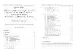
Figure 9.
UM0909
Host connection in SPI mode
MOSI
Host
STM32W
MISO
SCLK
nSSEL
nHwake
nStop
nSwake
Note:
The STM3W SPI channel configured in slave mode can support a data transfer rate of up to
5 Mbps.
7.1.2
UART protocol
The universal asynchronous receiver/transmitter (UART) protocol uses the following signals
to exchange data between the host MCU and the STM32W:
●
TXD data transmission pin
●
RXD data reception pin
In addition, three other GPIO signals can be used to manage the flow control between the
host MCU and the STM32W:
●
nSwake to wake up the STM32W when the host wants to start a communication.
●
nHwake to inform the host MCU that the STM32W has data available.
●
nStop, when asserted by the STM32W, to signal to the host that it is busy for internal
operation and that the host stops the data transmission.
The UART uses the following set: 115200-8-None-1-None.
Table 18 lists the signals and the corresponding pin numbers for an STM32W device.
Table 18.
GPIO
Direction
STM32W 48-pin package
pin number
STM32W 40-pin package
pin number
TXD
PB1
Output
30
25
RXD
PB2
Input
31
26
nHwake
PB3
Output
19
15
nSwake
PB4
Input
20
16
nStop
PA4
Output
26
22
Signal
42/53
UART signal and pin information
Doc ID 17097 Rev 4
UM0909
Using the STRF4CE library in Coprocessor mode
Figure 10. Host connection in UART mode
Host
TXD
RXD
RXD
TXD
STM32W
nHwake
nStop
nSwake
7.2
Packet format
Figure 11 shows the packet format used to exchange information between the host MCU
and the STM32W using the SPI or UART protocol.
Figure 11. Packet format
Start Byte Length Byte
Payload
End Byte
Where:
●
Start Byte: packet type: command, response (1 byte length). Codes are:
–
0xC0: RF4CE command packet
–
0xC1: RF4CE response packet
●
Length Byte: payload length not including End Byte (1 byte length)
●
Payload: depends on the Start Byte, it has the following format:
–
Command packet (0xC0)
The first byte is an RF4CE instruction code. Following bytes are instruction
parameters, if any. The parameters are sent as a packed stream of bytes in little
endian format.
–
Response packet (0xC1)
All response bytes
●
End Byte: Packet end with code 0xFC (1 byte length)
The maximum packet length is 200 bytes. Therefore, the maximum payload is 197 bytes
(including the 1 byte command packet and 196 bytes of parameters).
Doc ID 17097 Rev 4
43/53
Using the STRF4CE library in Coprocessor mode
7.3
UM0909
Serial RF4CE command codes
Table 19 lists all the RF4CE command codes used in the serial packet during
communication.
Table 19.
RF4CE coprocessor command codes
Command
44/53
Code
Description
NWKCOP_NOP
0x00 Nop instruction.
NWKCOP_NLDE_DATA_REQUEST
0x01 Data request function serial code.
NWKCOP_NLDE_DATA_INDICATION
0x02 Data indication function serial code.
NWKCOP_NLDE_DATA_CONFIRM
0x03 Data confirm function serial code.
NWKCOP_NLME_AUTO_DISCOVERY_REQUEST
0x04 Auto discovery request function serial code.
NWKCOP_NLME_AUTO_DISCOVERY_CONFIRM
0x05 Auto discovery confirm function serial code.
NWKCOP_NLME_COMM_STATUS_INDICATION
0x06 Comm status indication function serial code.
NWKCOP_NLME_DISCOVERY_REQUEST
0x07 Discovery request function serial code.
NWKCOP_NLME_DISCOVERY_INDICATION
0x08 Discovery indication function serial code.
NWKCOP_NLME_DISCOVERY_RESPONSE
0x09 Discovery response function serial code.
NWKCOP_NLME_DISCOVERY_CONFIRM
0x0A Discovery confirm function serial code.
NWKCOP_NLME_GET
0x0B Get request function serial code.
NWKCOP_NLME_PAIR_REQUEST
0x0C Pair request function serial code.
NWKCOP_NLME_PAIR_INDICATION
0x0D Pair indication function serial code.
NWKCOP_NLME_PAIR_RESPONSE
0x0E Pair response function serial code.
NWKCOP_NLME_PAIR_CONFIRM
0x0F Pair confirm function serial code.
NWKCOP_NLME_RESET
0x10 Reset request function serial code.
NWKCOP_NLME_RX_ENABLE
0x11 RX enable request function serial code.
NWKCOP_NLME_SET
0x12 Set request function serial code.
NWKCOP_NLME_START_REQUEST
0x13 Start request function serial code.
NWKCOP_NLME_START_CONFIRM
0x14 Start confirm function serial code.
NWKCOP_NLME_UNPAIR_REQUEST
0x15 Unpair request function serial code.
NWKCOP_NLME_UNPAIR_INDICATION
0x16 Unpair indication function serial code.
NWKCOP_NLME_UNPAIR_RESPONSE
0x17 Unpair response function serial code.
NWKCOP_NLME_UNPAIR_CONFIRM
0x18 Unpair confirm function serial code.
NWKCOP_NLME_UPDATE_KEY
0x19 Update key request function serial code.
NWKCOP_NWK_INIT
0x1A Init the RF4CE network.
NWKCOP_MAC_GET_EUI64
0x1B Get the IEEE Address.
Doc ID 17097 Rev 4
UM0909
Using the STRF4CE library in Coprocessor mode
Table 19.
RF4CE coprocessor command codes (continued)
Command
Code
Description
NWKCOP_FIRMWARE_VERSION
Get the firmware version. The information is
2 bytes; 0xyz 0kji, where x, y and z are the
major, minor and patch versions for the
0x1C
network coprocessor firmware. k, j, and i are
the major, minor and patch versions for
RF4CE library.
NWKCOP_POWER_DOWN
0x1D
NWKCOP_POWER_UP
0x1E Power up request for STM32W coprocessor.
NWKCOP_NWK_CONFIG
Helper function request to configure RF4CE
0x1F network coprocessor layer prior to cold start
initialization.
NWKCOP_NVM_ERASE
0x20
Support function call to erase the RF4CE
NVM network coprocessor memory.
NWKCOP_MAC_SET_EUI64
0x21
Set the IEEE Address only for test not
available for normal use.
Power down request for STM32W
coprocessor.
All the commands have a 4-byte response code to indicate the command outcome.
7.4
RF4CE serial communication code
The serial communication code is a byte sent after each communication which allows the
host microcontroller and STM32W to check for errors during the last transaction. The codes
are described in Table 20.
Table 20.
Serial communication error codes
Command
Code
Description
NWKCOP_PACKET_TOO_LONG
0x1000 00DA
Serial communication error packet too long.
NWKCOP_PACKET_DAMAGED
0x1000 00DB
Serial communication error packet
damaged.
NWKCOP_BUSY
0x1000 00DE
Serial communication error STM32W is
busy form more than a timeout.
NWKCOP_UNKNOWN_COMMAND
0x1000 00CB
Serial communication error unknown
command.
NWKCOP_UNKNOWN_PACKET_TYPE
0x1000 00CA
Serial communication error unknown
packet type (start byte unknown).
NWKCOP_WRONG_PARAM_LENGTH
0x1000 00C9
Serial communication error wrong
parameters length.
NWKCOP_END_PACKET_MISSING
0x1000 00C8
Serial communication error wrong
parameters length-end byte missing.
These serial response codes are different from the return codes of the RF4CE function
calls.
Doc ID 17097 Rev 4
45/53
Using the STRF4CE library in Coprocessor mode
7.5
UM0909
Physical level protocol
The following figures provide a graphical representation of a low-level protocol. They explain
how signals are managed during communication.
Figure 12 shows an example of signal management during a serial communication started
from the host side.
Figure 12. Serial communication started by the host (host side)
Figure 13 shows the low-level protocol from the STM32W side.
Figure 13. Serial communication started by the host (STM32W side)
If the STM32W starts a serial communication following an interrupt for a packet received,
the low-level protocol is as shown in Figure 14.
Figure 14. Callback response (STM32W side)
46/53
Doc ID 17097 Rev 4
UM0909
7.6
Using the STRF4CE library in Coprocessor mode
Serial communication packet format example
The following examples show an example of byte sequences in packets during serial
communication.
When the host launches a network init request nwk_Init(0xf, 1), the packet has the
following format:
C0
03
1A 0F 01
FC
Where:
0xC0 = command packet start byte
0x03 = payload length
0x1A = network init code
0x0F = node capabilities
0x01 = force cold start
0xFC = end packet
The STM32W executes the command and returns the following packet response:
C1
00 00 01 00
FC
Where:
0xC1 = command response start byte
0x00000100 = command response (RF4CE SAP pending)
0xFC = end packet
When the start_confirm callback function is received, the STM32W sends the following
packet to the host MCU:
C0
05
14 00 00 00 00
FC
Where:
0xC0 = command packet start byte
0x05 = payload length
0x14 = start confirm command code
0x00000000 = status ok
0xFC = end packet
7.7
Software code structure
This section briefly describes the software structure for both communication sides: the
network coprocessor and the host processor.
The network coprocessor runs a stand-alone application that basically consists of two state
machines:
●
receiveStateMachine() manages the RF4CE commands received from the host
processor, translates the bytes and then calls the RF4CE primitive.
●
sendStateMachine() manages the response command packets to send to the
network coprocessor. It also picks up the messages received from the air and
translates them as a byte sequence to send to the host processor using a serial
connection.
Doc ID 17097 Rev 4
47/53
Using the STRF4CE library in Coprocessor mode
UM0909
As explained above, the network coprocessor can manage two different types of serial
communications: SPI or UART. The user selects the SPI or UART interface during the
compilation time using a special preprocessor define. If the user declares the preprocessor
define SC_SPI, the network coprocessor manages the serial communication using the SPI
channel in slave mode. Otherwise, if the preprocessor variable is not defined, the
coprocessor uses the UART channel by default.
The host processor firmware is the interface between the user application and the network
coprocessor. It manages RF4CE requests from the user application and translates them as
a byte array to be sent through the serial channel.
The first step to execute in the main() is to initialize the serial communication UART or SPI
using the command hostSerialInit(). After this initialization, the user application can
execute the RF4CE commands.
Every RF4CE command is implemented using the following structure:
rf4ce_command (param)
{
/* function to copy the rf4ce param values inside a byte array */
cmd = create_array_byte_from_param (param)
/* send the packet bytes through the serial channel */
status = sendHostCmd (cmd)
if (status == SUCCESS)
/* wait the command response */
status = waitRspCmd(rsp)
if (status == SUCCESS)
memcpy(&status, &rsp[2], 4)
return status
}
The first step is to format the command param structure into a byte array according to the
packet format displayed above.
The sendHostCmd() function sends the packet bytes using the UART or SPI protocol
according to the serialInit() initialization function. This function also manages the
GPIO signals used to regulate the flow control before starting the communication (see the
figures in Section 7.5: Physical level protocol).
Every RF4CE command returns a 4-byte response that indicates the command result. The
waitRspCmd() function waits for the result from the coprocessor and returns the value to
the application.
A library for STM32F devices that interface with the STM32W and RF4CE coprocessor
firmware is provided as an example. The library and the associated demo are intended to be
run on an MB525 board fitted with an STM32F103VET6 microcontroller, but can be
customized and adapted to different boards and microcontrollers.
The rf4ce_cmds.c file manages all the RF4CE commands from the host side, while the
serial communication is managed by the stm32_sc.c file.
The RF4CE API provided to the host is described in Document [5].
48/53
Doc ID 17097 Rev 4
UM0909
7.8
Using the STRF4CE library in Coprocessor mode
RF4CE network coprocessor demo
The software demo highlights the same functions as those described in Section 4 as well as
how to work using an STM32W as the RF4CE network coprocessor.
The following boards are used to execute the demo:
7.8.1
●
MB525 with STM32F103VET6 processor (host board)
●
MB851 or MB954 with the STM32W108 processor (coprocessor board)
Building the firmware
The firmware for the MB525 board can be built from the IAR Embedded Workbench
sources, using the related IAR project file. Please note that the firmware on the host MCU
will be built for the UART interface by default.
The firmware running on the coprocessor board is only provided prebuilt and can be found
in the prebuilt directory.
7.8.2
Programming the firmware
To program the STM32F firmware, you can use the IAR Embedded Workbench.
To program the STM32W prebuilt coprocessor firmware, please use the stm32w_flasher.exe
file and follow the instructions provided in Section 4.3.
7.8.3
Setting up the boards
To run the demo, additional wiring between the host and the RF4CE coprocessor is
required. Table 21 provides information on the appropriate pins to connect on both boards. If
you use the default firmware on the host, connect the pins marked ‘Yes’ in the UART
column.
Table 21.
Coprocessor board to MB525 connection with UART and SPI mode
Coprocessor board
P1 connector
MB525 GPIO
connector
UART
SPI
nHWake
5
PE10
Yes
Yes
nSWake
6
PE11
Yes
Yes
nStop
10
PE12
Yes
Yes
MOSI
7
PB15
No
Yes
MISO
8
PB14
No
Yes
SCLK
9
PB13
No
Yes
nSSEL
11
PE13
No
Yes
UART-RX
16
PD5
Yes
No
UART-TX
15
PD6
Yes
No
GND
22
GND
Yes
Yes
Signal
The demo uses the MB525 USART1 with settings as specified in Table 6.
The LED3 on the MB525 is the “heartbeat” LED and it blinks every half second.
Doc ID 17097 Rev 4
49/53
Reference documents
UM0909
The LED1 is an application LED with the following meaning:
●
ON demo configured as TARGET
●
OFF demo configured as CONTROLLER, or UNCONFIGURED
●
BLINKING every half second, the board is initialized as TARGET and executing the
energy-scan and active-scan, to select the channel and the PANID, respectively
●
BLINKING every 100 msec, the device is executing a Discovery&Pair procedure
An IAR project is provided to show the network coprocessor reference code for the host
side.
See Section 4.4 for details on how to operate the demo.
8
Reference documents
[1] ZigBee RF4CE Specification, ZigBee Alliance document 094945r00ZB, Version 1.00,
March 17th, 2009.
[2] ZigBee RF4CE: CERC Profile Specification, ZigBee Alliance document 094946r00ZB,
March 17th, 2009.
[3] High-Definition Multimedia Interface Specification, HDMI Licensing, LLC, Version 1.3a,
5 November 10, 2006.
[4] STMicroelectronics, STM32W108HB datasheet, Doc ID 16252 Rev 3, December 2009
[5] ST RF4CE API Reference Guide, HTML document
[6] ZigBee RF4CE ZID Profile version 0.9, ZigBee Alliance document 105557r11cZB
March 8th, 2011
50/53
Doc ID 17097 Rev 4
UM0909
9
Terms and definitions
Terms and definitions
Table 22.
List of terms
Term
Meaning
ACK
Acknowledgment
API
Application programming interfaces
ZRC
ZigBee Remote Control
HDMI
High-Definition Multimedia Interface
MAC
Medium Access Control
NLDE
Network layer data entity
NLME
Network layer management entity
NVM
Non volatile memory
PAN
Personal Area Network
PHY
Physical layer
RC
Remote control device
RF4CE
Radio Frequency for Consumer Electronics
SAP
Service Access Point
ZID
ZigBee Input Device
Doc ID 17097 Rev 4
51/53
Revision history
10
UM0909
Revision history
Table 23.
Document revision history
Date
Revision
19-Feb-2010
1
Initial release.
31-Aug-2010
2
Added Section 7: Using the STRF4CE library in Coprocessor mode.
12-May-2011
3
Added Section 5: ZID demonstration application
4
Updated User Manual for new ZigBee RF4CE release including:
- replacement of Figure 7 and Figure 8
- update of Table 11
- add-up of Section 6: ZID, ZRC demonstration application
31-Aug-2012
52/53
Changes
Doc ID 17097 Rev 4
UM0909
Please Read Carefully:
Information in this document is provided solely in connection with ST products. STMicroelectronics NV and its subsidiaries (“ST”) reserve the
right to make changes, corrections, modifications or improvements, to this document, and the products and services described herein at any
time, without notice.
All ST products are sold pursuant to ST’s terms and conditions of sale.
Purchasers are solely responsible for the choice, selection and use of the ST products and services described herein, and ST assumes no
liability whatsoever relating to the choice, selection or use of the ST products and services described herein.
No license, express or implied, by estoppel or otherwise, to any intellectual property rights is granted under this document. If any part of this
document refers to any third party products or services it shall not be deemed a license grant by ST for the use of such third party products
or services, or any intellectual property contained therein or considered as a warranty covering the use in any manner whatsoever of such
third party products or services or any intellectual property contained therein.
UNLESS OTHERWISE SET FORTH IN ST’S TERMS AND CONDITIONS OF SALE ST DISCLAIMS ANY EXPRESS OR IMPLIED
WARRANTY WITH RESPECT TO THE USE AND/OR SALE OF ST PRODUCTS INCLUDING WITHOUT LIMITATION IMPLIED
WARRANTIES OF MERCHANTABILITY, FITNESS FOR A PARTICULAR PURPOSE (AND THEIR EQUIVALENTS UNDER THE LAWS
OF ANY JURISDICTION), OR INFRINGEMENT OF ANY PATENT, COPYRIGHT OR OTHER INTELLECTUAL PROPERTY RIGHT.
UNLESS EXPRESSLY APPROVED IN WRITING BY TWO AUTHORIZED ST REPRESENTATIVES, ST PRODUCTS ARE NOT
RECOMMENDED, AUTHORIZED OR WARRANTED FOR USE IN MILITARY, AIR CRAFT, SPACE, LIFE SAVING, OR LIFE SUSTAINING
APPLICATIONS, NOR IN PRODUCTS OR SYSTEMS WHERE FAILURE OR MALFUNCTION MAY RESULT IN PERSONAL INJURY,
DEATH, OR SEVERE PROPERTY OR ENVIRONMENTAL DAMAGE. ST PRODUCTS WHICH ARE NOT SPECIFIED AS "AUTOMOTIVE
GRADE" MAY ONLY BE USED IN AUTOMOTIVE APPLICATIONS AT USER’S OWN RISK.
Resale of ST products with provisions different from the statements and/or technical features set forth in this document shall immediately void
any warranty granted by ST for the ST product or service described herein and shall not create or extend in any manner whatsoever, any
liability of ST.
ST and the ST logo are trademarks or registered trademarks of ST in various countries.
Information in this document supersedes and replaces all information previously supplied.
The ST logo is a registered trademark of STMicroelectronics. All other names are the property of their respective owners.
© 2012 STMicroelectronics - All rights reserved
STMicroelectronics group of companies
Australia - Belgium - Brazil - Canada - China - Czech Republic - Finland - France - Germany - Hong Kong - India - Israel - Italy - Japan Malaysia - Malta - Morocco - Philippines - Singapore - Spain - Sweden - Switzerland - United Kingdom - United States of America
www.st.com
Doc ID 17097 Rev 4
53/53