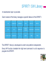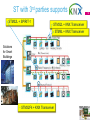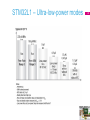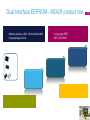
1
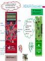
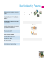
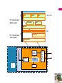
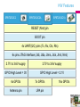
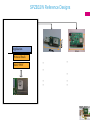
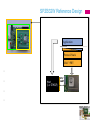
Wireless Embedded Connectivity ST Day October 2012 3 2.4GHz – 802.15.4 Wireless Sensor Gateway 169/ 433/ 868/ 916 MHz ommunication with 13.56MHz HF ISO15693/NFC RFID Solutions 2.4GHz Bluetooth Smart cable Wireless Embedded Connectivity - October 2012 Contents • • • • • • • 4 Application Drivers towards 2015 40% 35% 30% 25% 20% 15% 10% Appliances Medical HDD Ebooks STB 5% Infotainment Game Consoles Automotive Body TV 0% Computer Systems Printer -5% Flat Panel Monitor -10% Mobile Phone 1G/2G -15% -20% 100 1.000 10.000 Automotive Electronics Categories Consumer Electronics Categories Data Processing Categories Industrial Electronics Categories Wired Communications Categories Wireless Communications Categories 100.000 5 SPIRIT1 sub GHz RF transceiver What is SPIRIT1 ? • • • • • • • • • • • • • • • • 7 • Wide supply voltage range from 1.8 V to 3.6V Key Features • Configurable data rate from 1 to 500 kbps • Supported modulation schemes: • RF Receiver • Excellent receiver sensitivity (169 MHz) • • • Adjacent channel selectivity (1% PER – 20 bytes packet length) • • Blocking performance : • • IIP3 (Input third order intercept) • • RF Transmitter • Programmable Output Power 8 Key Features • Shutdown 2.5 nA Everything off Standby 650 nA SPI On, register retention Sleep 950 nA SPI on, register retention, Wakeup timer on Ready 400 uA SPI on, XTAL on • SPI access is available in all the modes (except Shutdown) since the SPI block is powered by a dedicated LDO (no SMPS required) • * (9mA RX, 433 MHz, FSK, 38.4kbps), similar also for other bands; SMPS ON, Vcc = 3.0V • ** (21mA TX, +11dBm, 169 MHz) 9 Key Features • • , Support for Automatic acknowledgment of received packets, retransmission and time-out protocol • (CCA) Engine : • Channel access mechanism, based on the rule ‘’Listen-before-talk’’ systems before transmitting ; this avoids the simultaneous use of the channel by different transmitter. • • Separate processing is available for secure data transfer , accessible via the SPI interface for host • Supports under MCU control • Calibration can be made each time the MCU decide to change frequency or MCU can save and restore calibration data to make the frequency hopping faster • 10 Main Block Description • • Support for channel configuration, packet handling and data buffering • Support Packet Formats (Basic, Stack, Wireless M-BUS ) • The Host MCU can stay in power down until a valid RF packet has been received, and then burst read the data, greatly reducing the power consumption and computing power required from the host MCU • • • • Provides data security support as it embeds an advanced encryption standard (AES) core which implements a cryptographic algorithm • The Host MCU can be used to read the chip temperature (e.g. it can be used to force radio recalibration) 11 12 • • • Write registers or FIFOs Read registers or FIFOs 17 Commands (State diagram, AES, FIFO flush) • • • • • • Interrupt signals Monitoring signals () Commands (TX/RX mode, Wake-up from external input) Input/output data (direct mode) Input/output reference clock (MCU clock out, 34.7 kHz for LDC mode input) Analog output: temperature sensor (GPIO 0) • Shutdown signal SPIRIT1 SW Library An abstraction layer is provided. Each module of the library manages a specific feature of the SPIRIT1. AES CALIBRATION COMMANDS CSMA DIRECT RF GENERAL GPIO IRQ LINEAR FIFO PACKET COMMON PACKET BASIC PACKET MBUS PACKET STACK REGISTERS QI RADIO TIMER TYPES The SPIRIT1 library is developed in order to be platform independent. Every API function translate the high level command in a bit sequence to program the SPIRIT1. 13 SPIRIT1 SDK Suite GUI RF performance evaluation • SPIRIT1 contains a GUI allowing to perform: • Radio configuration • RF tests (TX of un modulated carrier, TX PN9 sequence, RX activation) • Packet transmission/reception test with PER evaluation • AES engine encryption/decryption tests • Register read/write and dump Wireless Embedded Connectivity - October 2012 14 SPIRIT1 Kits Part number Type Purpose Content Dev kit RF performance evaluation, Point to Point RF communication, System Prototype development 2 x STM32L based motherboard 2 x SPIRIT1 RF modules 15 Order code STEVAL-IKR001V1 (169 MHz) STEVAL-IKR001V2 (315 MHz) STEVAL-IKR001V3 (433 MHz) STEVAL-IKR001V4 (868 MHz) STEVAL-IKR001V5 (915 MHz) STEVAL-IKR001V6 (920 MHz, ARIB T-108) 15 ST with 3rd parties supports • STM32L + SPIRIT-1 • STM32L + KNX Transceiver • STM8L + KNX Transceiver Solutions for Smart Buildings • STM32F4 + KNX Transceiver 16 ST Wireless M-BUS Stack features EN13757-4:2005 (S1, S1m, T1, T2, R2). • Radio band: 868 MHz EN13757-4:2011 (N mode) • Radio band 169 Mhz • GUI over USB Interface • Features under development: • Device type: Meter/Concentrator/Sniffer USB-HID WM-BUS SOFTWARE APPLICATION Database (MS-SQL Server Compact) 17 STM8L/STM32L1 EnergyLite™ platform – Ultra-low-power devices Flash memory size (in bytes) 8-bit and 32-bit MCU families 19 1M High-performance & 128 K Standard voltage & 16 K • STM8S Mainstream • STM8A Automotive • • STM8T Touch-sensing • STM32F4 – Cortex-M4 • STM32F2 – Cortex-M3 • STM32F1 – Cortex-M3 • STM32F0 – Cortex-M0 • – 2K Features STM8L/STM32L1 - Ultra-low-power MCUs • With the EnergyLite™ platform, STMicroelectronics is strongly committed to ultra-low-power MCUs • Energy saving • Ultra-low-power advanced architecture • High-performance core • Ultra-low-power in dynamic and static modes • New STM8L/STM32L1 series increase STM8/STM32 offer • Enriches both the ultra-low-power EnergyLite™ platform and STM8/STM32 portfolio • More than 100 part numbers for ultra-low-power lines 20 Ultra-low-power portfolio • ST’s 130 nm 21 process technology Notes: 1. 80 pins for STM8L15x/16x only 2. BGA100 on STM32L15x up to 128 Kbytes only Legend: STM8L: 151 without LCD, 152 with LCD and 162 with LCD and 128-bit AES STM32L1:151 without LCD, 152 with LCD and 162 with LCD and 128-bit AES Ultra-low-power series – 3 lines (1 μ μ Note: * Embedded EEPROM in the Flash AES 128bit ULP MSI MP U ET M US B FS SDI O FSM C 22 3x opamp s STM8L – Ultra-low-power modes 23 STM32L1 – Ultra-low-power modes 24 Ultra-low-power Discovery kits 25 STM32L1W June 2012 STM32L1W This part of doc is reserved, for more info contact your SILICA local FAE 27 Dual Interface EEPROM OCT. 2012 Dual Interface EEPROM – Introduction 29 Dual Interface EEPROM - M24LR product line • • • Memory density: 4-Kbit, 16-Kbit and 64-Kbit • Large package choice • Long range RFID • NFC (ISO15693 30 Dual Interface EEPROM - How it works • Based on Passive RFID technology • Just add a 13.56 MHz inductive antenna onto your PCB Dual Interface EEPROM Inductive antenna 31 M24LR64 block diagram I²C interface - industry standard - 1.8-5.5V, 400kHz VCC 64-bit Unique Identifier GND (FactoryProgrammed and Locked ) SCL ISO 15693 RF interface - industry standard - passive RFID technology - high-speed mode (up to 53 Kbit/s) 32 SDA I2C protocol E1 E0 AC1 AC0 Power management and I2C/RF arbitration unit I²C/RF arbitration EEPROM 64-Kbit EEPROM RF protocol Power extraction Password protection scheme What is M24LR16E Energy Harvesting? • When the Energy Harvesting function is ON, the M24LR16E can deliver the extra energy to other components Extra Energy RF host 33 M24LR16E Energy Harvesting Performance 00 3,5 A/m 100 mW 2,7 to 4,5 V 1,7 V 6 mA 01 2,4 A/m 66 mW 2,7 to 4,5 V 1,9 V 3 mA 10 1,6 A/m 33 mW 2,7 to 4,5 V 2,1 V 1 mA 11 1,0 A/m 18 mW 2,7 to 4,5 V 2,3 V 300 uA • Enables to remotely • Recharge your battery! • Power your board! 34 Embedded reader-writer: CR95HF chip • Full support of ST ISO15693 products with CR95HF • Software libraries • Reference design • Application notes 4-Kbit, 16-Kbit and 64-Kbit Dual I/F EEPROM 1, 2 and 64-Kbit ISO15693 RFID tag ICs Design your own embedded RF reader-writer (e.g. STM32 UM0586) 35 DEMO-CR95HF-A support • Ideal for demonstrations and performance assessment • Directly plugs on your computer (USB), comes with PC software - Source code CR95HF drivers.rar - Application note AN3355 Host system - Schematics (0017031-B-SCM.pdf) - Gerber files (0017031-B-Gerber.zip) USB - M24LRxx Application Software 2.0.zip -Application note AN3394 -Antenna design simplified basic tool 36 For example I can display the text message stored in the Dual Interface EEPROM M24LR-Discovery RF transceiver demo board (*) I AM COMING SOON STM8L SWIM connector Temperature sensor I²C connector M24LR04E 1 0 1 RF antenna 20 mm x 40 mm (0.79 in x 1.57 in) M24LR-board (*) I allow to power and exchange data with the M24LR04E but I am not the only one. 37 October 2012 BlueTooth (Blue Modules) IEEE 802.15.4 • Off-the-shelf RF • • Enable short development • is required for the integration of the modules in the target application for design of multiple platforms or multiple versions of the same platform • • • product Save 8-12 months in design cycle Significantly reduce engineering and production costs RF modules • reduce the effort and certification cost on the customer side Blue Modules Key Features Multiple antenna and transmission range options available Compliant with Bluetooth 2.1 or latest Bluetooth version 3.0 Integrated Serial Port Profile (SPP) and AT layer command interface Supporting communication with smart phones and Apple IOS Bluetooth enabled device FW upgradeable via UART Support of Low Power Use Modes Bluetooth Qualified and EPL listed RF Certified (FCC, CE, IC) Micro sized Form Factor Industrial Operating Temperature Range • • y x Blue Modules - Certifications Blue Modules are SPBT2532C2.AT SPBT2532C2.AT2 SPBT2632C1A.AT2 and for US and Canada. QD ID: Product type: End Product TGP Version: Core 2.1/2.1 + EDR TCRL2009-1 Core Spec Version: 2.1/2.1 +EDR Product Description: Bluetooth Module Measurements in accordance with : EN 300 328 V 1.7.1 (2004-11) EN 301 489-17 V 1.2.1:2002 EN 60950-1 CE 0051 ! QD ID: Product type: End Product TGP Version: Core 3.0 Core Spec Version: 3.0 Product Description: Bluetooth Module, spec V3.0 SPBT2632C2A.AT2 . Measurements in accordance with: EN 300 328 V 1.7.1 (2006-10) EN 301 489-17 V 2.1.1 (2009) EN 60950-1:2006 +A11:2009+A1:2010 CE 0051 ! QD ID: Product type: End Product TGP Version: Core 3.0 Core Spec Version: 3.0 Product Description: Bluetooth Module, spec V3.0 * Reports available on request Measurements n accordance with : EN 300 328 V 1.7.1 (2006-10) EN 301 489-17 V 2.1.1 (2009) EN 60950-1:2006 +A11:2009+A1:2010 CE 0051 ! FCC qualification is strictly related to RF section design; therefore it doesn’t apply to module without antenna on board. For this reason SPBT2532C2.AT module is not formally qualified, however it is FCC ready. FCC ID: IC: In accordance with FCC part 15, the SPBT2632C1A.AT2 is listed above as a modular transmitter device FCC ID: IC: In accordance with FCC part 15, the SPBT2632C2A.AT2 is listed above as a modular transmitter device Bluetooth SPBT2632C1A.AT2 Bluetooth SPBT2632C2A.AT2 Bluetooth Voltage regulator Bandpass filter LPO clock BT radio Crystal STM 32F SPP BT Protocol Stack Higher Layers SDAP RFCOMM *Only in AT2 iAP* SDP L2CAP HCI BT Protocol Stack Lower Layers LMP/LM Baseband/LC Voltage regulator Bandpass filter LPO clock BT radio Crystal STM 32F Flash RAM A AT(2) Interpreter Integrated Profiles SPP SDAP SDP L2CAP 2.1 + EDR 3.0 X X - X X X - X - X - X Locates/describes services from/to other devices Serial Port Profile (SPP) LMP/LM Discovers and connects to other devices Security (authentication) idle mode procedure: inquiry linking, paging, connection Service Discovery Profile (SDP) Baseband/LC Generic Access Profile (GAP) iAP* GAP RFCOMM ) Emulates legacy serial communication iPOD Accessory Protocol (iAP) Supports communication with Apple iOS Bluetooth enabled device* (*) The external Apple authentication coprocessor and MFI certification are required 44 HW Features SPBT2632C2A SPBT2532C2 SPBT2632C1A RESET (Nrst) pin BOOT pin 4x UART(I2C) pins (Tx, Rx, Cts, Rts) 6x pins JTAG interface (Jtdi, Jtdo, Jtms, Jtck, Jtrst, Nrst) 2.7V to 3.6V supply 2.7V to 3.6V supply GPIO High Level = 3V GPIO High Level = 2.1V 4x GPIOs 7x GPIOs Antenna pin LPA pin 16x GPIOs Power Consumption Performances Average Values ACL data 115KBaud UART at max throughput (Master) 39.0 mA 23 mA 23 mA ACL data 115KBaud UART at max throughput (Slave) 39.0 mA 27.5 mA 27.5 mA Connection, no data traffic, Master 28.9 mA 9.1 mA 9.1 mA Connection, no data traffic, Slave 34.5 mA 11.2 mA 11.2 mA Connection 375 ms sniff with LPO ---- 490 µA (*) 490 uA Page/inquiry scan, without deep sleep 33.2 mA 9.5 mA 9.5 mA Page/inquiry scan, with deep sleep, no LPO 7.2 mA 2.7 mA ------ Page/inquiry scan, with deep sleep and LPO ------ 520 µA (*) 520 µA Standby, without deep sleep 28.3 mA 8.6 mA 8.6 mA Standby with deep sleep, no LPO 2.1 mA 1.7 mA ------ Standby with deep sleep and LPO ----- 70 µA (*) 70 µA (*) External clock Evaluation Boards Blue Modules reference designs and evaluation boards for a fast evaluation of AT commands Power Supplied via the USB interface Compact and Small form factor LEDS connected to GPIO for testing purposes UART/USB bridge from Silicon Lab Typical Usage HyperTerminal HOST A: HOST B HyperTerminal Support tools SPBT2532C2.AT Bluetooth V2.1+EDR, Class2, antennaless, AT command FW SPBT2532C2.AT2 Bluetooth V2.1+EDR, Class2, antennaless, AT2 command FW SPBT2632C2A.AT2 Bluetooth V3.0, Class2, antenna, AT2 command FW SPBT2632C1A.AT2 Bluetooth V3.0, Class1, antenna, AT2 command FW STEVAL-SPBT2ATV2 USB dongle, evaluation board for SPBT2532C2.AT available USB dongle, evaluation board for SPBT2532C2.AT2 available USB dongle, evaluation board for SPBT2632C2A.AT2 available USB dongle, evaluation board for SPBT2632C1A.AT2 available Datasheets Application note AT command user manual Contact us @ [email protected] 48 802.15.4 Target Applications STM32W an open 802.15.4 Platform • • • • 32-bit ARM Cortex-M3 core running at 24 MHz Up to 256-Kbyte Flash and 16-Kbyte RAM Fully IEEE 802.15.4 compliant radio at 2.4 GHz Power management • • On-chip debug support • • • ARM JTAG/SWD Packet trace interface enables remote monitoring of radio messages ARM memory protection unit • • • • • • Deep sleep mode: <1 µA with RAM retention To detect erroneous software accesses Sleep timer, watchdog timer and GP timers AES-128 encryption acceleration Serial communication (UART/SPI/I²C) GPIO ADC (6 channels, first-order 12-bit sigma delta) 64K to 256-Kbytes Flash Memory 8K to 16-Kbytes RAM STM32W F/W combinations/portfolio ZigBee IP e:o 2Q/12 (Beta) RF4CE stack Network layer Standard library (optional) IPV6 network layer Standard library Network layer Standard library (for all versions) • The ST Simple MAC Library provides a set of APIs allowing access to the and functionality of the STM32W SoC: • RX/TX functionalities • Radio channel selection • control Network layer (optional) Standard library • Boost mode control • Radio and control • LQI and RSSI for received packets • Implementes Unslotted CSMA transmit support including CCA • Ability to enable/disable receiver • Automatic acknowledgement management SPZB32W Series Options Part Number Schema SPZB 32Wx y z .t – 54 STM32W108CC STM32W108CZ STM32W108HB STM32W108CB STM32W108C8 Also Integrated in the SPZB32W Series of RF Modules SPZB32W Key Features – Block Diagrams • Onboard 24MHz and 32kHz stable Xtals • Supply Range 2.1 V – 3.3 V • Exported the STM32W peripherals (UART, I2C, SPI, ADC) • JTAG interface for programming and debugging • SMD Modules with side pads for easy soldering and optical inspection • Operating in the industrial temperature range: -40 °C to + 85 °C • Small Form Factor: 26.5 mm x 16.4 mm • All the versions are pintopin compatible • Unless one GPIO between the normal and long range versions 32.768kHz Xtal 24MHz Xtal STM32W108 Balun BPF u.fl. SPZB32Wxy2.t – (TX: +3dbm : ITX: 32mA) 32.768kHz Xtal 24MHz Xtal STM32W108 PA/ LNA BPF u.fl. SPZB32Wxy1.t – (TX: up to 20dBm: ITX: 130 mA) Integration Modes SPZB32W Use modes Application Application Protocol Stack Protocol Stack MAC+PHY MAC+PHY Host (i.e. STM32F) SPI/ UART Tools and Reference Boards SPZB32W Reference Designs Application 8.5 cm. Protocol Stack MAC+PHY • • • • • • • • 58 SPZB32W Reference Design Application Protocol Stack MAC+PHY • • • • Host (i.e. STM32F) SPI/ UART 60 Thank you