1
UM0893
User manual
STM32W108xx SimpleMAC library
1
Introduction
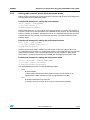
The STM32W108 SimpleMAC (media access control) library provides a set of APIs to
access the lower-MAC function of the STM32W108HB, STM32W108CB, STM32W108C8,
STM32W108CZ and STM32W108CC microcontrollers (STM32W108xx). These devices
integrate a 2.4 GHz IEEE 802.15.4-compliant transceiver featuring 16 channels and
supporting 250 Kbps transfers. The SimpleMAC library is designed to run on all
STM32W108 family devices. In addition, the SimpleMAC library will allow developing
specific stacks based on the IEEE 802.15.4 standard.
This document provides information on:
●
IEEE 802.15.4 protocol
●
STM32W108 SimpleMAC library features
●
How to build and run STM32W108 SimpleMAC demonstration applications
●
How to design an application using the STM32W108 SimpleMAC library APIs
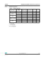
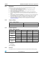
Table 1 lists the microcontrollers and tools concerned by this user manual.
Table 1.
Applicable products and tools
Type
Part numbers/product sub-classes
Microcontrollers
STM32W108xx
Evaluation tools to MCUs
STM32W-EXT
STM32W-SK
STM32W-RFCKIT
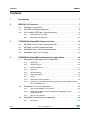
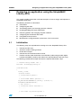
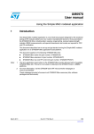
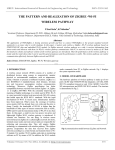
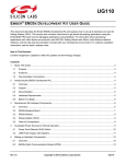
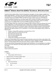
Figure 1.
STM32W108 SimpleMAC library
Customer Application
Network Layer (Optional)
Customer code
Librairies provided to ST
by customers
Silicon
IEEE 802.15.4 Upper MAC (Optional)
IEEE 802.15.4 Simple MAC
STM32W108 Device
MS18162V1
Note:
August 2012
The term application board refers to the STM32W108xx boards delivered with all available
STM32W108xx kits. This term is not used to refer to the STM32-Primer2 + MB850
platforms. For more information, visit the STM32W 32-bit RF microcontroller web pages at
www.st.com/stm32w. These web pages provide full access to all STM32W108xx resources
(kits, software packages and documents).
Doc ID 16995 Rev 10
1/54
www.st.com
Contents
UM0893
Contents
1
Introduction . . . . . . . . . . . . . . . . . . . . . . . . . . . . . . . . . . . . . . . . . . . . . . . . 1
2
IEEE 802.15.4 protocol . . . . . . . . . . . . . . . . . . . . . . . . . . . . . . . . . . . . . . . 7
3
4
2.1
IEEE 802.15.4 networks . . . . . . . . . . . . . . . . . . . . . . . . . . . . . . . . . . . . . . . 7
2.2
IEEE 802.15.4 device addressing . . . . . . . . . . . . . . . . . . . . . . . . . . . . . . . 8
2.3
PHY and MAC IEEE 802.15.4 protocol layers . . . . . . . . . . . . . . . . . . . . . . 8
2.3.1
IEEE 802.15.4 PHY layer . . . . . . . . . . . . . . . . . . . . . . . . . . . . . . . . . . . . 9
2.3.2
IEEE 802.15.4 MAC layer . . . . . . . . . . . . . . . . . . . . . . . . . . . . . . . . . . . 10
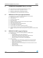
STM32W108 SimpleMAC library overview . . . . . . . . . . . . . . . . . . . . . . 14
3.1
IEEE 802.15.4 PHY layer supported features . . . . . . . . . . . . . . . . . . . . . 14
3.2
IEEE 802.15.4 MAC supported features . . . . . . . . . . . . . . . . . . . . . . . . . 14
3.3
SimpleMAC library API naming conventions . . . . . . . . . . . . . . . . . . . . . . 15
3.4
SimpleMAC Library APIs classes . . . . . . . . . . . . . . . . . . . . . . . . . . . . . . . 15
STM32W108 SimpleMAC demonstration applications . . . . . . . . . . . . 16
4.1
4.2
4.3
SimpleMAC sample demonstration application . . . . . . . . . . . . . . . . . . . . 16
4.1.1
IAR project . . . . . . . . . . . . . . . . . . . . . . . . . . . . . . . . . . . . . . . . . . . . . . . 16
4.1.2
Jumper settings . . . . . . . . . . . . . . . . . . . . . . . . . . . . . . . . . . . . . . . . . . . 16
4.1.3
Boards supported . . . . . . . . . . . . . . . . . . . . . . . . . . . . . . . . . . . . . . . . . 17
4.1.4
Serial I/O . . . . . . . . . . . . . . . . . . . . . . . . . . . . . . . . . . . . . . . . . . . . . . . . 18
4.1.5
LED description . . . . . . . . . . . . . . . . . . . . . . . . . . . . . . . . . . . . . . . . . . . 18
4.1.6
Button description . . . . . . . . . . . . . . . . . . . . . . . . . . . . . . . . . . . . . . . . . 18
4.1.7
Usage . . . . . . . . . . . . . . . . . . . . . . . . . . . . . . . . . . . . . . . . . . . . . . . . . . 18
4.1.8
Serial commands supported . . . . . . . . . . . . . . . . . . . . . . . . . . . . . . . . . 19
4.1.9
Running the sample demonstration application on the STM32-Primer2
with an MB850 board . . . . . . . . . . . . . . . . . . . . . . . . . . . . . . . . . . . . . . . 24
SimpleMAC PC sun GUI application . . . . . . . . . . . . . . . . . . . . . . . . . . . . 25
4.2.1
Run the SimpleMAC sun PC applet . . . . . . . . . . . . . . . . . . . . . . . . . . . . 25
4.2.2
Build, download and run the sample planet application on the
application board . . . . . . . . . . . . . . . . . . . . . . . . . . . . . . . . . . . . . . . . . . 27
4.2.3
Set up a star network . . . . . . . . . . . . . . . . . . . . . . . . . . . . . . . . . . . . . . . 27
SimpleMAC talk demonstration application . . . . . . . . . . . . . . . . . . . . . . . 29
4.3.1
2/54
IAR project . . . . . . . . . . . . . . . . . . . . . . . . . . . . . . . . . . . . . . . . . . . . . . . 29
Doc ID 16995 Rev 10
UM0893
Contents
4.4
4.5
4.6
5
4.3.2
Jumper settings . . . . . . . . . . . . . . . . . . . . . . . . . . . . . . . . . . . . . . . . . . . 29
4.3.3
Boards supported . . . . . . . . . . . . . . . . . . . . . . . . . . . . . . . . . . . . . . . . . 29
4.3.4
Serial I/O . . . . . . . . . . . . . . . . . . . . . . . . . . . . . . . . . . . . . . . . . . . . . . . . 30
4.3.5
LED description . . . . . . . . . . . . . . . . . . . . . . . . . . . . . . . . . . . . . . . . . . . 30
4.3.6
Button description . . . . . . . . . . . . . . . . . . . . . . . . . . . . . . . . . . . . . . . . . 30
4.3.7
Usage . . . . . . . . . . . . . . . . . . . . . . . . . . . . . . . . . . . . . . . . . . . . . . . . . . 31
SimpleMAC mouse demonstration application . . . . . . . . . . . . . . . . . . . . . 32
4.4.1
IAR projects . . . . . . . . . . . . . . . . . . . . . . . . . . . . . . . . . . . . . . . . . . . . . . 32
4.4.2
Jumper settings . . . . . . . . . . . . . . . . . . . . . . . . . . . . . . . . . . . . . . . . . . . 33
4.4.3
Boards supported . . . . . . . . . . . . . . . . . . . . . . . . . . . . . . . . . . . . . . . . . 33
4.4.4
Serial I/O . . . . . . . . . . . . . . . . . . . . . . . . . . . . . . . . . . . . . . . . . . . . . . . . 33
4.4.5
LED description . . . . . . . . . . . . . . . . . . . . . . . . . . . . . . . . . . . . . . . . . . . 33
4.4.6
Button description . . . . . . . . . . . . . . . . . . . . . . . . . . . . . . . . . . . . . . . . . 34
4.4.7
Usage . . . . . . . . . . . . . . . . . . . . . . . . . . . . . . . . . . . . . . . . . . . . . . . . . . 34
SimpleMAC OTA bootloader demonstration application . . . . . . . . . . . . . . 34
4.5.1
IAR project . . . . . . . . . . . . . . . . . . . . . . . . . . . . . . . . . . . . . . . . . . . . . . . 35
4.5.2
Jumper settings . . . . . . . . . . . . . . . . . . . . . . . . . . . . . . . . . . . . . . . . . . . 35
4.5.3
Boards supported . . . . . . . . . . . . . . . . . . . . . . . . . . . . . . . . . . . . . . . . . 35
4.5.4
Serial I/O . . . . . . . . . . . . . . . . . . . . . . . . . . . . . . . . . . . . . . . . . . . . . . . . 35
4.5.5
LED description . . . . . . . . . . . . . . . . . . . . . . . . . . . . . . . . . . . . . . . . . . . 37
4.5.6
Button description . . . . . . . . . . . . . . . . . . . . . . . . . . . . . . . . . . . . . . . . . 37
4.5.7
Usage . . . . . . . . . . . . . . . . . . . . . . . . . . . . . . . . . . . . . . . . . . . . . . . . . . 37
SimpleMAC nodetest application . . . . . . . . . . . . . . . . . . . . . . . . . . . . . . . 38
4.6.1
Building and downloading the SimpleMAC nodetest application . . . . . . 38
4.6.2
How to use the SimpleMAC nodetest application commands . . . . . . . . 38
Designing an application using the SimpleMAC Library APIs . . . . . . 39
5.1
Initialization . . . . . . . . . . . . . . . . . . . . . . . . . . . . . . . . . . . . . . . . . . . . . . . . 39
5.2
Configuring the radio . . . . . . . . . . . . . . . . . . . . . . . . . . . . . . . . . . . . . . . . 40
5.3
5.2.1
Radio sleep and wakeup . . . . . . . . . . . . . . . . . . . . . . . . . . . . . . . . . . . . 40
5.2.2
Calibrating the radio . . . . . . . . . . . . . . . . . . . . . . . . . . . . . . . . . . . . . . . . 40
5.2.3
Setting radio channel, power level and power mode . . . . . . . . . . . . . . . 41
Transmitting packets and managing transmit callbacks . . . . . . . . . . . . . . 42
5.3.1
Configuring the radioTransmitConfig variable . . . . . . . . . . . . . . . . . . . . 42
5.3.2
Setting and transmitting a packet . . . . . . . . . . . . . . . . . . . . . . . . . . . . . . 42
5.3.3
ISR callbacks for packet transmission . . . . . . . . . . . . . . . . . . . . . . . . . . 44
Doc ID 16995 Rev 10
3/54
Contents
UM0893
5.3.4
5.4
SFD event . . . . . . . . . . . . . . . . . . . . . . . . . . . . . . . . . . . . . . . . . . . . . . . 45
Receiving packets . . . . . . . . . . . . . . . . . . . . . . . . . . . . . . . . . . . . . . . . . . 45
5.4.1
Configuring radio filters for packet reception . . . . . . . . . . . . . . . . . . . . . 45
5.4.2
ISR callbacks for packet reception . . . . . . . . . . . . . . . . . . . . . . . . . . . . . 47
5.5
Configuring the coordinator filter mode . . . . . . . . . . . . . . . . . . . . . . . . . . 48
5.6
Radio AES security . . . . . . . . . . . . . . . . . . . . . . . . . . . . . . . . . . . . . . . . . 49
5.7
Radio MAC timer . . . . . . . . . . . . . . . . . . . . . . . . . . . . . . . . . . . . . . . . . . . 49
5.8
Other radio features . . . . . . . . . . . . . . . . . . . . . . . . . . . . . . . . . . . . . . . . . 49
5.8.1
Radio energy detection . . . . . . . . . . . . . . . . . . . . . . . . . . . . . . . . . . . . . 49
5.8.2
Radio CCA . . . . . . . . . . . . . . . . . . . . . . . . . . . . . . . . . . . . . . . . . . . . . . . 50
5.8.3
Radio packet trace interface (PTI) . . . . . . . . . . . . . . . . . . . . . . . . . . . . . 50
5.8.4
Send a tone or a carrier wave . . . . . . . . . . . . . . . . . . . . . . . . . . . . . . . . 50
6
References . . . . . . . . . . . . . . . . . . . . . . . . . . . . . . . . . . . . . . . . . . . . . . . . 51
7
List of acronyms . . . . . . . . . . . . . . . . . . . . . . . . . . . . . . . . . . . . . . . . . . . 51
8
Revision history . . . . . . . . . . . . . . . . . . . . . . . . . . . . . . . . . . . . . . . . . . . 52
4/54
Doc ID 16995 Rev 10
UM0893
List of tables
List of tables
Table 1.
Table 2.
Table 3.
Table 4.
Table 5.
Table 6.
Table 7.
Table 8.
Table 9.
Table 10.
Table 11.
Table 12.
Table 13.
Table 14.
Table 15.
Table 16.
Table 17.
Table 18.
Table 19.
Table 20.
Table 21.
Table 22.
Table 23.
Table 24.
Table 25.
Table 26.
Table 27.
Table 28.
Table 29.
Table 30.
Table 31.
Table 32.
Table 33.
Table 34.
Applicable products and tools . . . . . . . . . . . . . . . . . . . . . . . . . . . . . . . . . . . . . . . . . . . . . . . . 1
IEEE 802.15.4 PHY parameters . . . . . . . . . . . . . . . . . . . . . . . . . . . . . . . . . . . . . . . . . . . . . . 9
General MAC frame format. . . . . . . . . . . . . . . . . . . . . . . . . . . . . . . . . . . . . . . . . . . . . . . . . 12
PHY frame format . . . . . . . . . . . . . . . . . . . . . . . . . . . . . . . . . . . . . . . . . . . . . . . . . . . . . . . . 13
Jumper settings . . . . . . . . . . . . . . . . . . . . . . . . . . . . . . . . . . . . . . . . . . . . . . . . . . . . . . . . . 16
Boards supported . . . . . . . . . . . . . . . . . . . . . . . . . . . . . . . . . . . . . . . . . . . . . . . . . . . . . . . . 17
Serial I/O . . . . . . . . . . . . . . . . . . . . . . . . . . . . . . . . . . . . . . . . . . . . . . . . . . . . . . . . . . . . . . . 18
LED description . . . . . . . . . . . . . . . . . . . . . . . . . . . . . . . . . . . . . . . . . . . . . . . . . . . . . . . . . 18
Button description . . . . . . . . . . . . . . . . . . . . . . . . . . . . . . . . . . . . . . . . . . . . . . . . . . . . . . . . 18
Serial commands supported . . . . . . . . . . . . . . . . . . . . . . . . . . . . . . . . . . . . . . . . . . . . . . . . 19
Detailed command description . . . . . . . . . . . . . . . . . . . . . . . . . . . . . . . . . . . . . . . . . . . . . . 20
STM32-Primer2 SM SUN menu versus input commands. . . . . . . . . . . . . . . . . . . . . . . . . . 25
SimpleMAC sun PC applet command options . . . . . . . . . . . . . . . . . . . . . . . . . . . . . . . . . . 26
Jumper settings . . . . . . . . . . . . . . . . . . . . . . . . . . . . . . . . . . . . . . . . . . . . . . . . . . . . . . . . . 29
Boards supported . . . . . . . . . . . . . . . . . . . . . . . . . . . . . . . . . . . . . . . . . . . . . . . . . . . . . . . . 29
Serial I/O . . . . . . . . . . . . . . . . . . . . . . . . . . . . . . . . . . . . . . . . . . . . . . . . . . . . . . . . . . . . . . . 30
LED description . . . . . . . . . . . . . . . . . . . . . . . . . . . . . . . . . . . . . . . . . . . . . . . . . . . . . . . . . 30
Button description . . . . . . . . . . . . . . . . . . . . . . . . . . . . . . . . . . . . . . . . . . . . . . . . . . . . . . . . 30
Jumper settings . . . . . . . . . . . . . . . . . . . . . . . . . . . . . . . . . . . . . . . . . . . . . . . . . . . . . . . . . 33
Boards supported . . . . . . . . . . . . . . . . . . . . . . . . . . . . . . . . . . . . . . . . . . . . . . . . . . . . . . . . 33
LED description . . . . . . . . . . . . . . . . . . . . . . . . . . . . . . . . . . . . . . . . . . . . . . . . . . . . . . . . . 33
Button description . . . . . . . . . . . . . . . . . . . . . . . . . . . . . . . . . . . . . . . . . . . . . . . . . . . . . . . . 34
Jumper settings . . . . . . . . . . . . . . . . . . . . . . . . . . . . . . . . . . . . . . . . . . . . . . . . . . . . . . . . . 35
Boards supported . . . . . . . . . . . . . . . . . . . . . . . . . . . . . . . . . . . . . . . . . . . . . . . . . . . . . . . . 35
Serial I/O . . . . . . . . . . . . . . . . . . . . . . . . . . . . . . . . . . . . . . . . . . . . . . . . . . . . . . . . . . . . . . . 36
Support commands. . . . . . . . . . . . . . . . . . . . . . . . . . . . . . . . . . . . . . . . . . . . . . . . . . . . . . . 36
LED description . . . . . . . . . . . . . . . . . . . . . . . . . . . . . . . . . . . . . . . . . . . . . . . . . . . . . . . . . 37
Button description . . . . . . . . . . . . . . . . . . . . . . . . . . . . . . . . . . . . . . . . . . . . . . . . . . . . . . . . 37
RadioTransmitConfig members . . . . . . . . . . . . . . . . . . . . . . . . . . . . . . . . . . . . . . . . . . . . . 42
Packet FCF configuration as 0x0821 . . . . . . . . . . . . . . . . . . . . . . . . . . . . . . . . . . . . . . . . . 43
FCF field of the packet sent to a coordinator node . . . . . . . . . . . . . . . . . . . . . . . . . . . . . . . 48
List of references . . . . . . . . . . . . . . . . . . . . . . . . . . . . . . . . . . . . . . . . . . . . . . . . . . . . . . . . 51
List of acronyms . . . . . . . . . . . . . . . . . . . . . . . . . . . . . . . . . . . . . . . . . . . . . . . . . . . . . . . . . 51
Document revision history . . . . . . . . . . . . . . . . . . . . . . . . . . . . . . . . . . . . . . . . . . . . . . . . . 52
Doc ID 16995 Rev 10
5/54
List of figures
UM0893
List of figures
Figure 1.
Figure 2.
Figure 3.
Figure 4.
Figure 5.
Figure 6.
Figure 7.
Figure 8.
Figure 9.
Figure 10.
Figure 11.
Figure 12.
Figure 13.
Figure 14.
Figure 15.
Figure 16.
Figure 17.
6/54
STM32W108 SimpleMAC library . . . . . . . . . . . . . . . . . . . . . . . . . . . . . . . . . . . . . . . . . . . . . 1
Peer-to-peer topology . . . . . . . . . . . . . . . . . . . . . . . . . . . . . . . . . . . . . . . . . . . . . . . . . . . . . . 7
Star topology. . . . . . . . . . . . . . . . . . . . . . . . . . . . . . . . . . . . . . . . . . . . . . . . . . . . . . . . . . . . . 8
PHY and MAC layers . . . . . . . . . . . . . . . . . . . . . . . . . . . . . . . . . . . . . . . . . . . . . . . . . . . . . . 8
Device-to-coordinator communications . . . . . . . . . . . . . . . . . . . . . . . . . . . . . . . . . . . . . . . 11
Coordinator-to-device communications in beacon-enabled networks . . . . . . . . . . . . . . . . 11
Coordinator-to-device communications in non beacon-enabled networks . . . . . . . . . . . . . 12
Star network created by sun . . . . . . . . . . . . . . . . . . . . . . . . . . . . . . . . . . . . . . . . . . . . . . . . 24
Planet associated to sun. . . . . . . . . . . . . . . . . . . . . . . . . . . . . . . . . . . . . . . . . . . . . . . . . . . 24
Data sent from planet to sun . . . . . . . . . . . . . . . . . . . . . . . . . . . . . . . . . . . . . . . . . . . . . . . 24
Sun plus 5 planets . . . . . . . . . . . . . . . . . . . . . . . . . . . . . . . . . . . . . . . . . . . . . . . . . . . . . . . 24
Network down . . . . . . . . . . . . . . . . . . . . . . . . . . . . . . . . . . . . . . . . . . . . . . . . . . . . . . . . . . . 24
SimpleMAC sun PC applet flash image check . . . . . . . . . . . . . . . . . . . . . . . . . . . . . . . . . . 26
SimpleMAC sun node forms an IEEE 802.15.4 network . . . . . . . . . . . . . . . . . . . . . . . . . . 26
Planet device joining the network . . . . . . . . . . . . . . . . . . . . . . . . . . . . . . . . . . . . . . . . . . . . 27
Planet sending data to the sun . . . . . . . . . . . . . . . . . . . . . . . . . . . . . . . . . . . . . . . . . . . . . . 28
Sun node with 5 planets . . . . . . . . . . . . . . . . . . . . . . . . . . . . . . . . . . . . . . . . . . . . . . . . . . . 28
Doc ID 16995 Rev 10
UM0893
2
IEEE 802.15.4 protocol
IEEE 802.15.4 protocol
The IEEE 802.15.4 is a standard which specifies the physical layer (PHY) and the media
access control (MAC) layer for low-rate wireless personal area networks (LR-WPANs).
The main features are as follows:
●
Channel access via carrier sense multiple access with collision avoidance (CSMA-CA)
●
Optional time slotting and network beaconing
●
Message acknowledgement
●
Multilevel security
●
Suitable for long battery devices, with selectable latency to match different power
requirements (sensors, remote monitoring, …)
The IEEE 802.15.4 standard distinguishes between two types of devices:
–
Full function devices (FFD)
Full function devices can be common nodes or coordinators of personal area
networks (PANs). They can communicate with any device connected to the
network and relay messages. FFD devices are suitable for any type of network
topology.
–
Reduced function devices (RFD)
Reduced function devices are simple devices with limited resources and
communication capabilities. They can only communicate with FFDs and can never
act as coordinators. RFD devices are only suitable for star networks.
2.1
IEEE 802.15.4 networks
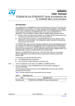
Two types of network topologies are supported:
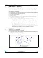
●
Peer-to-peer networks where each device can communicate with any other device as
long as they are in range of one another.
Figure 2.
Peer-to-peer topology
Doc ID 16995 Rev 10
7/54
IEEE 802.15.4 protocol
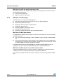
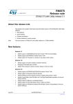
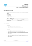
●
Star networks where communications are established between devices and a single
central controller, called the PAN coordinator.
Figure 3.
2.2
UM0893
Star topology
IEEE 802.15.4 device addressing
A unique PAN identifier is assigned to each independent PAN built on a channel.
All devices connected to the network have a unique 64-bit extended address. This address
is used for direct communications through the PAN. A device can also use a short 16-bit
address which is allocated by the PAN coordinator when the device is associated to the
network.
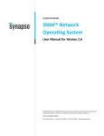
2.3
PHY and MAC IEEE 802.15.4 protocol layers
Figure 4 shows the IEEE 802.15.4 MAC and PHY layers.
Figure 4.
8/54
PHY and MAC layers
Doc ID 16995 Rev 10
UM0893
2.3.1
IEEE 802.15.4 protocol
IEEE 802.15.4 PHY layer
The PHY layer manages the physical RF transceiver. It is also in charge of the following
tasks:
●
Activating and deactivating of the radio transceiver
●
Energy detection for the current channel
●
Indicating link quality for the received packets
●
CCA for the CSMA-CA
●
Selecting channel frequency
●
Data transmission and reception
The standard specifies two PHY layers:
●
●
868/915 MHz direct sequence spread spectrum (DSSS) PHY
–
One 20 Kbps channel in the European 868 MHz band
–
Ten 40 Kbps channels in the 915 MHz ISM band (from 902 to 928 MHz)
2 450 MHz DSSS PHY supporting sixteen 250 Kbps channels in the 2.4 GHz band
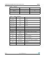
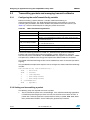
Table 2.
IEEE 802.15.4 PHY parameters
Parameter
Sensitivity @ 1% PER
2.4 GHz PHY
868/915 MHz PHY
-85 dBm
-92 dBm
Receiver maximum input level
-20 dBm
Adjacent channel rejection
0 dB
Alternate channel rejection
30 dB
Output power (lowest maximum)
-3 dBm
Transmit modulation accuracy
EVM < 35% for 1000 chips
Number of channels
16
1/10
5 MHz
Single-channel at 2 MHz
250 kbps
62.5 ksymbol/s
2 Mchip/s
20/40 kbps
20/40 ksymbol/s
300/600 kchip/s
O-QPSK with half-sine pulse
shaping
BPSK with raised cosine
pulse shaping
Channel spacing
Transmission rates:
Data rate
Symbol rate
Chip rate
Chip modulation
IEEE 802.15.4 PHY CCA
The following CCA modes are supported:
●
CCA mode 1: energy above threshold (lowest)
●
CCA mode 2: carrier sense (medium)
●
CCA mode 3: carrier sense with energy above threshold (strongest)
Doc ID 16995 Rev 10
9/54
IEEE 802.15.4 protocol
UM0893
IEEE 802.15.4 PHY link quality indication (LQI)
The LQI characterizes the strength and/or quality of a received packet. The measurement
may be implemented using:
2.3.2
●
Receiver energy detection
●
Signal-to-noise ratio estimation
IEEE 802.15.4 MAC layer
The MAC layer is in charge of the following tasks:
●
Generating network beaconing for devices acting as PAN coordinators
●
Synchronizing with the beacons
●
Supporting PAN association and dissociation
●
Supporting device security
●
Using the CSMA-CA for channel access
●
Managing the GTS mechanism
●
Providing a reliable link between peer-to-peer MAC entities.
IEEE 802.15.4 MAC data transfer
The IEEE 802.15.4 MAC protocol supports two data transfer models that can be selected by
the PAN coordinator:
●
The non beacon-enabled mode, in which the MAC is simply ruled by unslotted CSMACA.
●
The beacon enabled mode, in which beacons are periodically sent by the coordinator to
synchronize the associated nodes and identify the PAN. Access to the channel is ruled
by slotted CSMA-CA using the superframe structure.
For detailed information about the IEEE 802.15.4 slotted/unslotted CSMA-CA and the
superframe structure, refer to the related IEEE 802.15.4 standard specification.
IEEE 802.15.4 MAC device-to-coordinator data transfer
In beacon-enabled networks, the devices search for the beacon to synchronize with the
superframe structure. They then transmit data using slotted CSMA-CA.
In non beacon-enabled networks, the devices simply transmit data using unslotted CSMACA.
10/54
Doc ID 16995 Rev 10
UM0893
Figure 5.
IEEE 802.15.4 protocol
Device-to-coordinator communications
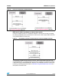
IEEE 802.15.4 MAC coordinator-to-device data transfer
In beacon-enabled networks, the coordinator indicates in the beacon that data is pending.
The device periodically listens to the beacons and transmits a data request MAC command
using slotted CSMA-CA if necessary.
Figure 6.
Coordinator-to-device communications in beacon-enabled networks
In non beacon-enabled networks, devices transmit a data request MAC command using
unslotted CSMA-CA. If a coordinator data transmission is pending, the coordinator transmits
a data frame using unslotted CSMA-CA. Otherwise, the coordinator transmits a data frame
containing a zero-length payload. Refer to IEEE 802.15.4 general MAC frame format for a
description of the MAC frame.
Doc ID 16995 Rev 10
11/54
IEEE 802.15.4 protocol
Figure 7.
UM0893
Coordinator-to-device communications in non beacon-enabled networks
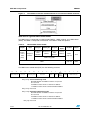
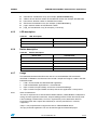
IEEE 802.15.4 general MAC frame format
The MAC frame is composed of a MAC header (MHR), a MAC payload, and a MAC footer
(MFR). The MHR is composed of fixed fields. The address fields are optional.
Table 3.
General MAC frame format
2 bytes
Frame
control
field
(FCF)
1 byte
Sequence
number
0/2 bytes
0/2/8 bytes
0/2 bytes
0/2/8
bytes
Destination
PAN
identifier
Destination
address
Source
PAN
identifier
Source
address
Variable
2 bytes
Frame
payload
FCS
MAC
payload
MFR
Addressing fields
MHR
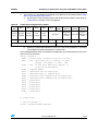
The MAC frame control field (FCF) has the following structure:
15
14
Source
addressing mode
13
12
Reserved
11
10
Destination
addressing mode
9
8
Reserved
7
6
IntraPAN
5
4
Bits [15:14] Source addressing mode
00: PAN identifier and address field are not present.
01: reserved
10: Address field contains a 16-bit short address.
11: Address field contains a 64-bit extended address.
Bits [12:13] Reserved
Bits [11:10] Destination addressing mode
00: PAN identifier and address field are not present.
01: reserved
10: Address field contains a 16-bit short address.
11: Address field contains a 64-bit extended address.
Bits [7:9] Reserved
12/54
Doc ID 16995 Rev 10
3
MAC
Ack.
Security
frame
request
enabled
pending
2
1
MAC frame type
0
UM0893
IEEE 802.15.4 protocol
Bit 6 Intra-PAN
1: frame to be sent within same PAN
0: frame to be sent to another PAN
Bit 5 Acknowledge request
1: device sends an acknowledgment frame when it receives a valid frame
0: device does not send an acknowledgment frame when it receives a valid frame
Bit 4 MAC frame pending
1: sender device has additional data to send to the receiver
0: sender device does not have any more data for the receiver
Bit 3 Security enabled
1: frame is cryptographically protected by the MAC layer
0: frame is not cryptographically protected by the MAC layer
Bits [2:0] MAC frame type
000: Beacon
001: Data
010: Ack
011: MAC command
100: Reserved
111: Reserved
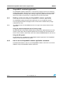
IEEE 802.15.4 PHY frame format
Table 4 shows the PHY frame structure.
Table 4.
PHY frame format
4 bytes
1 byte
Preamble
SFD
1 byte
Frame length
(7 bits)
SHR
Variable
Reserved
(1 bit)
PHR
PHY payload
field (PSDU)
PHY payload
●
The preamble field is used by the transceiver to perform chip and symbol
synchronization with an incoming message. The preamble is composed of 32 binary
zeros.
●
The SFD field (start-of-frame delimiter) is an 8-bit field indicating the end of the
synchronization preamble and the start of the packet data. The SFD must be equal to
10100111b.
●
The frame length field is 7-bit long. It specifies the total number of bytes contained in
the PHY payload field (PSDU). Its value ranges from 0 to 127.
●
The PHY payload field (PSDU) contains the MAC frame.
For more details about the PHY and MAC frames, refer to the IEEE 802.15.4 standard
specification.
Doc ID 16995 Rev 10
13/54
STM32W108 SimpleMAC library overview
3
UM0893
STM32W108 SimpleMAC library overview
This section describes the STM32W108 SimpleMAC library features:
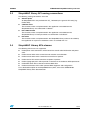
3.1
●
IEEE 802.15.4 PHY features supported by the library
●
IEEE 802.15.4 MAC features supported by the library
●
SimpleMAC library APIs naming conventions and classes.
IEEE 802.15.4 PHY layer supported features
The SimpleMAC library supports the following IEEE 802.15.4 PHY features:
3.2
●
Radio channel selection on 2.4 GHz band
●
Radio calibration
●
Transmission power control
●
Boost mode control
●
Selection of alternate transmission path for external power amplifier
●
Radio sleep and wakeup control
●
Time stamp of received and transmitted packets
●
LQI and RSSI for received packets
●
Transmit single carrier frequency (diagnostic function)
●
Transmit continuous stream of random symbols (diagnostic function)
●
Automatic seeding pseudo random number generator using hardware random number
source
IEEE 802.15.4 MAC supported features
The SimpleMAC library supports the following IEEE 802.15.4 MAC features:
●
Transmit functions
–
●
14/54
Unslotted CSMA transmit support including CCA
–
Backoff periods determined by pseudo random number generator
–
CRC generation and CRC data insertion into packets
–
Automatic reception and verification of acknowledgement
Receive functions
–
Packet reception with hardware filtering, correlator error and CRC checking
–
Ability to set node addresses and PAN identifier (for receive filtering only)
–
Hardware filters fully exposed
–
Automatic transmission of acknowledgement with software control over frame
pending indication
–
Promiscuous mode
–
Ability to enable/disable receivers
Doc ID 16995 Rev 10
UM0893
3.3
STM32W108 SimpleMAC library overview
SimpleMAC library API naming conventions
The following naming conventions are used:
●
General prefix
All SimpleMAC APIs are prefixed with “ST_” followed by the general API family (e.g.
Radio, AES).
●
Callback suffix
The functions which are implemented in the application and called from the
SimpleMAC library are suffixed with “Callback”.
●
ISR callback suffix
The functions which are implemented in the application and called from the
SimpleMAC library in interrupt context are suffixed with “IsrCallback”.
●
ISR suffix
The functions which are implemented in the SimpleMAC library and must be called by
the application in response to hardware events are suffixed with “Isr”.
3.4
SimpleMAC Library APIs classes
The following API classes are supported:
●
Radio power state control APIs which control the overall radio initialization and power
state.
●
Radio channel APIs which control channel selection and calibration.
●
Radio transmit APIs which control the transmission of packets.
●
Radio receive APIs which control the reception of packets.
●
Radio cryptography APIs which provide an interface to the hardware AES coprocessor.
●
Radio MAC timer APIs to interface with the MAC timer.
●
Radio miscellaneous APIs which perform MAC diagnostic and configuration.
For a detailed description of the SimpleMAC library APIs, refer to the STM32W108
SimpleMAC Library APIs documentation.
Doc ID 16995 Rev 10
15/54
STM32W108 SimpleMAC demonstration applications
4
UM0893
STM32W108 SimpleMAC demonstration applications
Four simpleMAC demonstration applications are delivered within the SimpleMAC software
library package which is available from the STM32W 32-bit RF microcontroller web pages at
www.st.com/stm32w:
●
SimpleMAC sample demonstration applications (sun and planet roles)
●
SimpleMAC talk demonstration application
●
SimpleMAC mouse demonstration application
●
SimpleMAC OTA bootloader demonstration application
●
SimpleMAC nodetest application
The demonstration applications designed to run on an application board may require a
serial communication interface.
The following subsections provide a description of the building and running steps of the
demonstration applications using the IAR projects delivered within the SimpleMAC software
library package as a reference. The available workspaces provide reference examples for
the STM32W108CC boards.
4.1
SimpleMAC sample demonstration application
This is an example of an RF application that shows an 802.15.4 star topology using the
STM32W108 microcontroller.
4.1.1
IAR project
To use the project with IAR Embedded Workbench for ARM, follow the instructions below:
4.1.2
1.
Open the Embedded Workbench for ARM.
2.
From the File > Open > Workspace menu, open the related IAR workspace.
3.
Select the configuration that you want to build.
4.
Select Project > Rebuild All to recompile and link the entire application.
5.
To launch a debug session, connect the IAR Jlink to the JTAG connector (P1) in your
board.
6.
Select Project > Download and Debug. The related binary image is downloaded into
the STM32W108CC Flash memory and the interactive debug session is started.
7.
Connect the application board to a PC USB port. Open a hyperterminal on the
corresponding USB virtual COMx port with the configuration, as described in
Section 4.1.4: Serial I/O.
Jumper settings
Table 5.
16/54
Jumper settings
Jumper name
All configurations
JP1, if available
Irrelevant
P1, if available
1-2 (battery) 5-6 (USB)
Doc ID 16995 Rev 10
UM0893
4.1.3
STM32W108 SimpleMAC demonstration applications
Boards supported
Table 6.
Boards supported
Board name
Board
revision
Primer2 + MB850 A
A
X
A,B,C
STM32W108xB STM32W108CC
Sun
Planet
NA
X
-
X
NA
X
X
D
NA
X
X
X
A,B
X
NA
X
X
C
NA
X
X
X
MB953A
X
NA
X
X
MB953B
NA
X
X
X
A
X
NA
X
X
B
NA
X
X
X
MB851
MB954
MB950A + MB953
MB951
X = supported
- = not supported
NA = not applicable
Doc ID 16995 Rev 10
17/54
STM32W108 SimpleMAC demonstration applications
4.1.4
UM0893
Serial I/O
The application listens for commands sent over the serial port. The serial port configuration
is:
Table 7.
4.1.5
Parameter name
Value
Unit
Baud rate
15200
bit/sec
Data bits
8
bit
Parity
None
bit
Stop bits
1
bit
LED name
STM32W108xB_SUN
STM32W108xB_PLANET
D1
Not used
Not used
D3
Not used
LED description
Table 8.
4.1.6
LED description
– On when joined a network
– Off when not joined
Button description
Table 9.
4.1.7
Serial I/O
Button description
Button name
STM32W108xB_SUN
STM32W108xB_PLANET
S1
Not used
Join network
S2
If available
Not used
S3
If available
Not used
S4
If available
Not used
S5
If available
Not used
Usage
This demonstration represents an Application Framework which sets up a basic star
topology and supports parent and child roles. To prevent name collisions with other
software, applications, and implementations, the parent role is called "sun" and the child role
is called "planet". These roles are implemented using specific definitions: SUN_ROLE and
PLANET_ROLE.
Executing the form command on a node loaded with the sun image provokes the node to
form a network. Executing the form command, on a node loaded with the planet image,
provokes the node to join the network formed by the sun node. Executing the leave
command provokes each node to leave the network. There cannot be multiple suns on the
same PAN ID.
18/54
Doc ID 16995 Rev 10
UM0893
STM32W108 SimpleMAC demonstration applications
The sample applications demonstrate:
●
Management of a simple direct transmission queue
●
Management of a simple indirect transmit queue including interaction with the receive
ISR, in order to handle the setting of the ACK frame pending bit, in response to a data
poll
●
Sleepy planets automatically send the radio to sleep when there is no more data to
transmit
●
Retry of packet on ACK failure
●
Active search for a sun implemented as simple blocking code
●
Energy search for a channel with low activity implemented as simple blocking code
●
Capture of transmit SFD time and insertion of time value into packet payload.
●
Conversion of correlator error count to LQI
●
Planet deep sleeping
Note:
All references to "sleep" and "sleepy" refer to deep sleep operations.
4.1.8
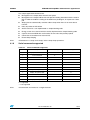
Serial commands supported
Table 10.
Serial commands supported
Command
Description
STM32W108xB_SUN
STM32W108xB_PLANET
i
Display status information
X
X
f
Form a network
X
-
j
Join a network
-
X
l
Leave a network
X
X
s
Send data
X
X
c
Clear indirect transmit queue
X
-
p
Poll for data
-
X
r
Adjust send/poll rates
X
X
t
Display the planet table
-
X
o
Enter OTA bootloader mode
X
X
u
Enter Uart bootloader mode
X
X
?
Display this help menu
X
X
X = supported
- = not supported
Note:
All commands are invoked as a single character.
Doc ID 16995 Rev 10
19/54
STM32W108 SimpleMAC demonstration applications
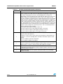
Table 11.
Command
20/54
UM0893
Detailed command description
Description
i
Display status information displays the status of the node including information
such as:
– Network role
– Radio on/off state
– In or out of a network
– Channel
– Power
– EUI64
– PAN ID
– Node ID
– Send rate
– Poll rate
f
Form a network can only be executed while not already in a network. To form the
network, the node first initializes all persistent states then loops over all channels
searching for the channel with the lowest energy. The node dwells on each channel
taking multiple energy readings and records the highest energy level seen on every
channel. After obtaining a maximum energy reading for each channel, the node
selects the channel with the lowest maximum energy reading and configures itself
for that channel. The node then assigns itself a random PAN ID and assigns itself
the short address (node ID) 0x0000.
j
Join a network can only be executed while not already in a network. To join the
network, the node first initializes all persistent states then loops over all channels
searching for a channel with a sun. On each channel, the node transmits a sun
search broadcast packet and then waits for 200 ms for a sun available response.
If the node does not receive a sun available broadcast response after 200 ms, it
moves on to the next channel. If the node never receives a sun available response
or cannot complete the join process on any channel, the node indicates this fact to
the user and the user must invoke the join network command to try again.
The sun only sends the sun available response if there is room in the sun's planet
table. If the node does receive a sun available response, the response includes the
sun's PAN ID as the source PAN ID. If the node receives more than one sun
available response, the node tries to join the first response it receives.
Multiple suns on the same PAN ID are not valid, and there is no collision detection
for this situation. The planet sends a join request unicast packet using long
addressing and the sun's PAN ID. When the sun receives the join request, the sun
attempts to place to the planet in its planet table. The planet table is a fixed size. If
there is no room in the planet table, the sun responds with a join denied unicast
packet. If there is room in the planet table, the sun allocates a new short ID to the
planet, puts the planet in its planet table, and responds with a join accepted unicast
packet. There is no error detection if the join process fails before the join accepted
or denied packet has been received.
The sun does not remove planets from its planet table unless the planet specifically
sends a leaving network packet.
Doc ID 16995 Rev 10
UM0893
STM32W108 SimpleMAC demonstration applications
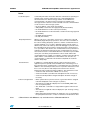
Table 11.
Detailed command description (continued)
Command
Description
l
Leave a network can only be executed while already in a network. On sun nodes,
this command simply clears out key persistent state indicating it is no longer active
in a network. On planet nodes, this command sends a message to the sun
indicating that it is leaving the network. After sending the leaving message, key
persistent state is cleared out indicating it is no longer active in a network. The sun
does not acknowledge the leave message. After the leave is complete, on either a
sun or planet, forming a new network or joining an existing network is now allowed.
s
Send data can only be executed while already in a network. Send a single unicast
message. Automatically sending is controlled with the command “r - Adjust send/poll
rates". On planet nodes, a unicast message is placed on the direct transmission
queue and sent directly to the sun. On sun nodes, the user is first presented a table
of all planet nodes that are active in the sun's planet table. The user must then
select the node that the unicast message will be sent to. The unicast message is
placed on the indirect transmission queue. The message will stay on the queue until
that destination node polls for messages, at which point the sun will transmit the
message to the planet. These unicast messages use short addresses for both the
destination and source. The payload includes the 16-bit VDD_PADS measurement
as provided by the related API. Additionally, the 20-bit (3 byte) transmit SFD time of
the packet being transmitted is added to the end of the packet payload while the
packet is being transmitted. The MSB of the 3-byte SFD time is set last, indicating to
the receiver that the SFD was correctly placed into the packet.
c
Clear indirect transmit queue can only be executed while already in a network. It
forcefully clears the indirect transmit queue of all packets that are not already in
flight. This command is necessary due to: the limited size of the indirect transmit
queue, the persistence of the packets in the queue, and the fact that a planet with
pending data could disappear from the network and never poll for its pending data.
p
Poll for data can only be executed while already in a network and this command is
ineffectual on sun nodes. Poll once. Automatically polling is controlled with the
command "r - Adjust send/poll rates". Non-sleepy planets are allowed to poll but,
since the sun will not queue up indirect transmission for non-sleepy planets, the poll
will never result in receiving messages. This command sends a short unicast poll
packet to the sun. If the sun has data pending for the polling planet, the sun sets the
frame pending bit in the MAC ACK. When the planet receives the MAC ACK, it
observes the frame pending bit. If the frame pending bit is not set, the planet
immediately goes back to sleep. If the frame pending bit is set, the planet stays
awake for 200 ms with receiver on waiting for the sun to transmit the message. After
200 ms, the planet goes back to sleep.
Doc ID 16995 Rev 10
21/54
STM32W108 SimpleMAC demonstration applications
Table 11.
22/54
UM0893
Detailed command description (continued)
Command
Description
r
Adjust send/poll rates can only be executed while already in a network. Sending
data at a regular rate is valid on both sun and planets, but polling at a regular rate is
only valid on sleepy planets. The rate command implements a sub menu to
independently control automatic/periodic sends and polls. Rates are chosen as the
number of quarter-seconds between the events. A rate of zero will turn off that
event. The send data command performs a single send whereas the rate command
enables automatic and regular sending. The poll command performs a single poll
whereas the rate command enables automatic and regular polling. It is valid to issue
a send command while the send rate is greater than zero, and it is valid to issue a
poll command while the poll rate is greater than zero. Manually issuing a send or poll
command while the rates are greater than zero will simply add those commands to
the queue and not disrupt rate controlled operations. This command implements a
series of sub menus which configure:
– which planets get regular messages from the sun
– the rate at which the sun sends regular messages to the planet
– the rate at which the planet sends regular messages to the sun
– the rate at which the planet polls for messages from the sun
t
Display the planet table on sun nodes command displays the entire planet table.
Each entry in the table indicates:
– whether or not the entry is active, which means the planet is still joined the sun
– whether or not there is pending data in the indirect transmission queue for that
planet
– the short address (node ID) of that planet
– the long address (EUI64) of that planet
o
Enter OTA bootloader mode activates the IAP bootloader in Over the Air mode.
The user is requested to provide the application binary image over the air (see the
stm32w_flasher -i rf option or the bootloader_demo application example).
u
Enter Uart bootloader mode activates the IAP bootloader in Uart mode. The user
is requested to provide the application binary image through the uart interface (see
the stm32w_flasher -b option).
?
Display help menu shows the top level commands and their associated single
character command.
Doc ID 16995 Rev 10
UM0893
STM32W108 SimpleMAC demonstration applications
Notes
Packet Reception:
Commands print status information while the commands are operating. For
example, when forming a network, the form command displays the
selected channel, the channel energy, and the chosen PAN ID. For
received packets, only data (unicast) messages are printed. These
messages are the result of the send command or the rate command. When
a node receives a data message, it prints:
– the short address of the sender (hex number)
– VDD_PADS, stored in the message payload (decimal number)
– the 20-bit SFD time from the receiver (hex number)
– the 20-bit SFD time from the transmitter, stored in the message payload
(hex number)
– the RSSI (decimal number)
– the LQI (hex number)
Deepsleep Behavior:
When a node is not connected to a network or is a planet, the node will
immediately begin deep sleep operations. The user is also informed that
the node is entering deepsleep operations, and the command interface is
dormant. Wakeup can occur due to debugger activity, periodic events, or
UART activity. If the node wakes up due to the debugger or periodic events,
the node will inform the user that it is awake and return to deep sleep as
soon a possible. In this situation, the command interface stays dormant. To
wakeup from deepsleep and reactivate the command interface, the user
must send a character on the UART. When the node wakes up from UART
activity, the user will be prompted that the node is awake and that the
command interface is capable of accepting a command. The node will stay
awake with the command interface active until the user executes any
command. After a command is executed and completed, the node will
return to deep sleep.
Periodic Events:
In addition to constantly driving network activity in the main loop, the
application performs periodic and scheduled events. The timing of two of
these periodic events, send and poll, is controlled via the rate command. In
addition to the send and poll events, there is a periodic maintenance event
that occurs every 60 seconds and performs tasks that are critical to
keeping the chip in optimal operating conditions. The maintenance event:
– checks the radio and invokes calibration, if necessary
– checks the 24 MHz crystal bias trim and adjusts the trim, if necessary
– checks the GPIO pad drive strength and adjusts the drive strength, if
necessary
Primer2 sun application: – When a planet device joins the network, a green box with the assigned
node ID is displayed on the LCD (up to 5 planets).
– The Primer2 sun application displays the received VDD_PADS value
from each planet (in mV)
– The "Send data" command is not supported through the Primer2 LCD
menu
– The Primer2 sun application doesn't display the "poll" message coming
from a planet
– When interacting with the Primer2 sun application, it is recommended to
keep the planet send rate to a value not lower than the default set value.
Note:
STM32-Primer2 with MB850 is only available with the STM32W108B-SK kit.
Doc ID 16995 Rev 10
23/54
STM32W108 SimpleMAC demonstration applications
UM0893
You need to use at least two boards to perform the demonstration. Follow the instructions:
4.1.9
1.
Load the one board with the sun role application.
2.
Load the remaining boards with the planet role application.
3.
Open a terminal on the sun board and type f.
4.
Push the S1 button on all the planet role boards in sequence, waiting for LED D3 to
switch on indicating a successful connection to the sun.
5.
All the planets should have LED D3 on, and you should now see messages coming
from planets to the sun.
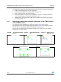
Running the sample demonstration application on the STM32-Primer2
with an MB850 board
The STM32-Primer2 with MB850 sun application supports some of the sample
demonstration events and input commands described in Section 4.1 through the STM32Primer2 interface resources (LCD, joystick with button, touch screen).
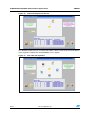
These events and commands are mapped to graphic events displayed on the STM32Primer2 LCD, as shown below.
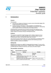
Figure 8.
Star network created
by sun
Figure 9.
Planet associated to
sun
Figure 11. Sun plus 5 planets
24/54
Doc ID 16995 Rev 10
Figure 10. Data sent from
planet to sun
Figure 12. Network down
UM0893
STM32W108 SimpleMAC demonstration applications
The scenario shown in Figure 8 is obtained by selecting SM SUN from the LCD menu. The
input commands listed in Table 12 can then be issued by selecting the corresponding item
from the related LCD menu.
Table 12.
STM32-Primer2 SM SUN menu versus input commands
Menu items
Planet table
Leave network
Sun infos
Note:
Description
Displays the list of planets
Quits the network
Displays the sun node status and information.
The STM32-Primer2 with MB850 is only available with the STM32W108B-SK kit.
The STM32-Primer2 with MB850 sun application also supports an interface communication
channel through a virtual USB COM. Connect a mini USB cable to the bottom-right side of
the STM32-Primer2 and to a PC USB port, and configure the related hyperterminal to
115 200 bps, 8-bits, no parity and flow control, and one stop bit.
The STM32-Primer2 sun application displays the VDD values (in mV) received from each
application board planet.
The Send data command is not supported by the STM32-Primer2 LCD menu.
The STM32-Primer2 sun application does not display data polled from a planet.
4.2
SimpleMAC PC sun GUI application
A PC applet targeting the SimpleMAC sun application is available.
The main functions of the SimpleMAC sun PC applet are:
4.2.1
●
Sun node forming an IEEE 802.15.4 network
●
Giving all information about the sun node (channel, pan ID, node ID,, eui64, tx power, ..)
●
Handling planet nodes joining the network
●
Handling planet nodes leaving the network once
●
Sun node exiting the network
●
Sun node receiving data from each joined planet node
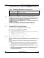
Run the SimpleMAC sun PC applet
The application board is automatically configured when launching the SimpleMAC sun PC
applet.
To run the SimpleMAC sun PC applet on an application board, the following steps are
required:
1.
Connect the application board to the PC using a mini USB cable with P2 fitted in
position 5-6 (power from USB). A virtual COM port should appear in the Windows
Device Manager (or connect the USB dongle directly to a PC USB port).
2.
From Windows, launch the SimpleMAC sun Application.exe PC applet. A PC applet
GUI appears.
3.
Select the serial port matching the port assigned by the Windows Device Manager. If
the firmware on the application board is not present, the application uploads the
firmware through the serial port.
Doc ID 16995 Rev 10
25/54
STM32W108 SimpleMAC demonstration applications
UM0893
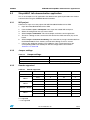
Figure 13. SimpleMAC sun PC applet flash image check
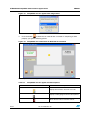
4.
Push the button
to allow the sun node to form a network. If everything is done
properly, you get the following picture:
Figure 14. SimpleMAC sun node forms an IEEE 802.15.4 network
The SimpleMAC sun PC applet also offers these command options:
Table 13.
SimpleMAC sun PC applet command options
Command
Description
Displays all information about the sun node
Displays a table giving information about planets
Allows the sun node to leave the network
26/54
Doc ID 16995 Rev 10
UM0893
4.2.2
STM32W108 SimpleMAC demonstration applications
Build, download and run the sample planet application on the
application board
To build, download and run the sample planet application on an application board, use the
related IAR project provided within the SimpleMAC software library package following the
instructions described in Section 3.3.
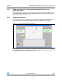
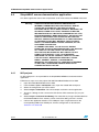
4.2.3
Set up a star network
On the planet node, press button S1 to join the network formed by the STM32W108xx sun
node. Once joined, the planet node is displayed on the SimpleMAC sun PC applet.
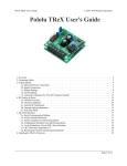
Figure 15. Planet device joining the network
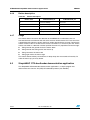
When a planet device sends data to the sun device (at a periodic rate), a line connecting the
transmitting planet to the sun is displayed on the SimpleMAC sun PC applet, as well as the
sent application board VDD_PADS value (in mV).
Doc ID 16995 Rev 10
27/54
STM32W108 SimpleMAC demonstration applications
UM0893
Figure 16. Planet sending data to the sun
This identifies which planet is in transmission mode, if there is more than one planet device
(up to 5 planets supported by the SimpleMAC sun PC applet)
Figure 17. Sun node with 5 planets
28/54
Doc ID 16995 Rev 10
UM0893
4.3
STM32W108 SimpleMAC demonstration applications
SimpleMAC talk demonstration application
This is an example of an RF application that demonstrates point-to-point 802.15.4 wireless
communication using the STM32W108 microcontroller.
4.3.1
IAR project
Follow these steps to use the project with IAR Embedded Workbench for ARM:
4.3.2
1.
Open the Embedded Workbench for ARM.
2.
From the File > Open > Workspace menu, open the related IAR workspace.
3.
Select the configuration that you want to build.
4.
Select Project > Rebuild All. This will recompile and link the entire application.
5.
To launch a debug session, connect the IAR Jlink to the JTAG connector (P1) on the
board.
6.
Select Project > Download and Debug. The related binary image is downloaded into
the STM32W108CC Flash memory and interactive debug session is started.
7.
Connect the application board to a PC USB port. Open a hyperterminal on the
corresponding USB virtual COMx port with the configuration as described in
Section 4.3.4: Serial I/O.
Jumper settings
Table 14.
4.3.3
Jumper settings
Jumper name
STM32W108xB
JP1, if available
Irrelevant
P1, if available
1-2 (battery) 5-6 (USB)
Boards supported
Table 15.
Boards supported
Board name
Board revision
STM32W108xB
STM32W108CC
Talk
Primer2 + MB850 A
A
X
NA
-
A,B,C
X
NA
X
D
NA
X
X
A,B
X
NA
X
C
NA
X
X
MB953A
X
NA
X
MB953B
NA
X
X
A
X
NA
X
B
NA
X
X
MB851
MB954
MB950A + MB953
MB951
X = supported
- = not supported
Doc ID 16995 Rev 10
29/54
STM32W108 SimpleMAC demonstration applications
UM0893
NA = not applicable
4.3.4
Serial I/O
The application listens for keys typed in one node and sends them to the remote node. The
remote node listens for RF messages, which it outputs to the serial port. Everything typed in
one node is visible to the other node and vice versa.
Table 16.
4.3.5
Serial I/O
Parameter name
Value
Unit
Baud rate
15200
bit/sec
Data bits
8
bit
Parity
None
bit
Stop bits
1
bit
LED description
Table 17.
4.3.6
LED description
LED name
Event
STM32W108xB
D1
Button press
– On when a button is pressed
– Off when the message corresponding to
the button press is sent
D3
Button press
None
D1
RF message received
See Button description
D3
RF message received
See Button description
D1+D3
Error in transmission
Flash together for one second
Button description
Button presses on the board result in sending an RF message to the other board. The action
taken by the other board is described in Table 18.
Table 18.
Button description
Button name
30/54
STM32W108xB
S1
Toggle LED D1 in the remote node
S2
Toggle LED D3 in the remote node
S3
Toggle LEDs D1 and D3 in the remote node
S4
Blinks LED D1 for a few seconds in the remote node
S5
Blinks LED D3 for a few seconds in the remote node
Doc ID 16995 Rev 10
UM0893
4.3.7
STM32W108 SimpleMAC demonstration applications
Usage
This demonstration illustrates two use cases:
●
RS232 cable replacement
This scenario illustrates an existing point-to-point communication based on a wired
RS232 connection, which is replaced by 802.15.4 2.4GHz RF link.
●
Simple remote control implementation
This scenario illustrates a button push on one board (remote control), resulting in LED
activities on the other board (actuator).
The demonstration requires two boards. Follow the instructions:
Note:
1.
Load the two boards with the talk application.
2.
Open a terminal on both boards so you can see the keystrokes sent from one terminal
to the other. This is an RS232 cable replacement demonstration.
3.
Push any button on one board and observe the corresponding action on the other
board LEDs. This is a simple remote control implementation.
Notes and limitations
You cannot use more than two nodes with a talk application in the same radio range
because RF conflicts will arise.
When pressing a button on the Talk Application Board 1, LED D1 is turned on indicating a
packet is going to be sent.
If something is wrong with the current RF communication (packet transmission failed or no
acknowledgment received from the Talk Application Board 2), pressing a button on the Talk
Application Board 1 makes the Talk Application Board 1 LEDs (D1 and D3) blink for a few
seconds.
Doc ID 16995 Rev 10
31/54
STM32W108 SimpleMAC demonstration applications
4.4
UM0893
SimpleMAC mouse demonstration application
This demo application shows how to implement an RF mouse based on MEMS movement.
Warning:
4.4.1
THIS APPLICATION SOFTWARE IS PROVIDED FOR
INTERNAL DEMONSTRATION PURPOSE ONLY AND NO
OTHER USE IS PERMITTED. THIS APPLICATION IS
PROVIDED ON AN "AS IS" BASIS, WITHOUT WARRANTY OF
ANY KIND, EITHER STATUTORY, EXPRESS OR IMPLIED,
INCLUDING WITHOUT LIMITATION, WARRANTIES OF TITLE,
NON-INFRINGEMENT, MERCHANTABILITY, SATISFACTORY
QUALITY AND FITNESS FOR A PARTICULAR PURPOSE.
WITHOUT LIMITING THE GENERALITY OF THE FOREGOING,
ST EXPRESSLY DOES NOT WARRANT THE ACCURACY,
SAFETY, OR USEFULNESS FOR ANY PURPOSE, OF THE
SOFTWARE APPLICATION.
ST HEREBY DISCLAIMS, TO THE FULLEST EXTENT
PERMITTED BY APPLICABLE MANDATORY LAW, ANY AND
ALL LIABILITY FOR THE USE OF THE SOFTWARE
APPLICATION, INCLUDING BUT NOT LIMITED TO ANY
LIABILITY IN CONTRACT, TORT, OR OTHERWISE,
WHATEVER THE CAUSE THEREOF, LIABILITY FOR ANY
LOSS OF PROFIT, BUSINESS OR GOODWILL OR ANY
DIRECT, INDIRECT, SPECIAL, CONSEQUENTIAL,
INCIDENTAL OR PUNITIVE COST, DAMAGES OR EXPENSE
OF ANY KIND, HOWSOEVER ARISING UNDER OR IN
CONNECTION WITH THIS USE.
IAR projects
An IAR workspace is also provided for the SimpleMAC MEMS mouse demonstration
application.
Follow these steps to use the project with IAR Embedded Workbench for ARM:
32/54
1.
Open the Embedded Workbench for ARM.
2.
From the File > Open > Workspace menu, open the related IAR workspace.
3.
Select the configuration you want to build.
4.
Select Project > Rebuild All. This will recompile and link the entire application.
5.
To launch a debug session, connect the IAR Jlink to JTAG connector (P1) on your
board.
6.
Select Project > Download and Debug. The related binary image is downloaded into
the STM32W108CC Flash memory, and an interactive debug session is started.
7.
Connect the application board to a PC USB port. Open a hyperterminal on the
corresponding USB virtual COMx port, with the configuration as described in
Section 4.4.4: Serial I/O.
Doc ID 16995 Rev 10
UM0893
4.4.2
STM32W108 SimpleMAC demonstration applications
Jumper settings
Table 19.
4.4.3
Jumper settings
Jumper name
STM32W108xB_TX
STM32W108xB_RX
JP1, if available
Fitted
Irrelevant
P1, if available
2 (battery) 5-6 (USB)
5-6
Boards supported
Table 20.
Boards supported
Board name
Board
revision
Primer2 + MB850 A
A
X
A,B
MB851
MB954
STM32W108x STM32W108
B
CC
TX
RX
NA
-
-
X
NA
X
-
C
X
X
X
X
D
NA
X
X
X
A
X
NA
X
-
B
X
NA
X
X
C
NA
X
X
X
MB953A
X
NA
X
X
MB953B
NA
X
X
X
A
X
NA
-
X
B
NA
X
-
X
MB950A + MB953
MB951
X = supported
- = not supported
NA = not applicable
4.4.4
Serial I/O
Debug information only provided in case of errors.
4.4.5
LED description
Table 21.
LED description
LED name
STM32W108xB_TX
STM32W108xB_RX
D1
On when RF transmission is taking place
Not used
D3
Not used
On when an RF packet is received
Doc ID 16995 Rev 10
33/54
STM32W108 SimpleMAC demonstration applications
4.4.6
Button description
Table 22.
Button description
Button name
4.4.7
UM0893
STM32W108xB_TX
STM32W108xB_RX
S1
Left click, Wakeup
Not used
S2, if available
Left click, Wakeup
Not used
S3, if available
Right click, Wakeup
Not used
S4, if available
Right click, Wakeup
Not used
S5, if available
Wakeup
Not used
Usage
The mouse demo is based on the detection of the MEMS axis accelerations that are
translated to mouse movement and sent to the receiver attached to the PC. Flash one of the
supported boards with the tx image and Flash another board with the rx image. Connect the
mouse receiver to the PC and to use the mouse transmitter as a mouse for your PC. Tilt the
mouse transmitter in a direction and the speed of the mouse is proportional to the tilt angle.
●
Tilting towards the ground moves the mouse down
●
Tilting towards the ceiling moves the mouse up
●
Tilting left moves the mouse left
●
Tilting right moves the mouse right
The mouse demonstration puts the device in deep sleep after 10 seconds of inactivity. To
wake the mouse up, push any button.
4.5
SimpleMAC OTA bootloader demonstration application
The SimpleMAC OTA bootloader demonstration application is a simple program that
demonstrates the Over the Air (OTA) ST bootloader protocol (see AN3262).
34/54
Doc ID 16995 Rev 10
UM0893
4.5.1
STM32W108 SimpleMAC demonstration applications
IAR project
Follow these steps to use the project with the IAR Embedded Workbench for ARM:
4.5.2
1.
Open the IAR Embedded Workbench for ARM.
2.
From the File > Open > Workspace menu, open the related IAR workspace.
3.
Select the configuration you want to build.
4.
Select Project > Rebuild All. This will recompile and link the entire application.
5.
To launch a debug session, connect the IAR Jlink to the JTAG connector (P1) on the
board.
6.
Select Project > Download and Debug. The related binary image is downloaded into
the STM32W108CC Flash memory, and the interactive debug session is started.
7.
Connect the application board to a PC USB port. Open a hyperterminal on the
corresponding USB virtual COMx port with the configuration as described in
Section 4.5.4: Serial I/O.
Jumper settings
Table 23.
4.5.3
Jumper settings
Jumper name
STM32W108xB
JP1, if available
Irrelevant
P1, if available
5-6
Boards supported
Table 24.
Boards supported
Board name
Board revision
STM32W108xB
STM32W108CC
ota_bootloader
Primer2 + MB850 A
A
X
NA
-
A,B,C
X
NA
X
D
NA
X
X
A,B
X
NA
X
C
NA
X
X
MB953A
X
NA
X
MB953B
NA
X
X
A
X
NA
X
B
NA
X
X
MB851
MB954
MB950A + MB953
MB951
X = supported
- = not supported
NA = not applicable
4.5.4
Serial I/O
The application listens for commands sent over the serial port with the following settings:
Doc ID 16995 Rev 10
35/54
STM32W108 SimpleMAC demonstration applications
Table 25.
UM0893
Serial I/O
Parameter name
Value
Unit
Baud rate
115200
bit/sec
Data bits
8
bit
Parity
None
bit
Stop bits
1
bit
The list of supported commands is:
Table 26.
36/54
Support commands
Command name
Command parameters
Description
loadImage
None
Find first node in bootloader mode and load test
image to it
findBLNodes
None
Return the list of nodes in bootloader mode in the
radio range
setDestEui64
eui64
Set the destination EUI64 for bootloader
commands
getDestEui64
None
Return the currently used EUI64 for bootloader
commands
get
None
GET command (see AN3262)
bget
None
GET command broadcast (see AN3262)
getid
None
GET_ID command (see AN3262)
bgetid
None
GET_ID command broadcast (see AN3262)
getversion
None
GET_VERSION command (see AN3262)
bgetversion
None
GET_VERSION command broadcast (see
AN3262)
read
address bytes
write
address bytes data
WRITE command: write bytes of data to memory
address (see AN3262)
writeIncremental
bytes data
WRITE_INCREMENTAL command: write bytes of
data to next memory address (see AN3262)
erase
pages page_list
ERASE command: erase a list of pages in Flash
(see AN3262)
go
address
help
None
READ command: read bytes of memory from
address (see AN3262)
GO command: Jump to address (see AN3262)
List commands
Doc ID 16995 Rev 10
UM0893
4.5.5
STM32W108 SimpleMAC demonstration applications
●
eui64 format: hexadecimal array (for example, {0080E10200000798})
●
address format: decimal number or hexadecimal number (for example, 0xaabbccdd)
●
bytes format: decimal number or hexadecimal number
●
data format: hexadecimal array (for example, {aabbccddeeff0011})
●
pages: decimal number or hexadecimal number
●
page_list: hexadecimal array (for example, {11121314})
LED description
Table 27.
4.5.6
LED description
LED name
STM32W108xB
D1
Not used
D3
Not used
Button description
Table 28.
Button description
Button name
4.5.7
STM32W108xB
S1
Not used
S2, if available
Not used
S3, if available
Not used
S4, if available
Not used
S5, if available
Not used
Usage
The bootloader demonstration illustrates how to use the bootloader OTA commands
described in AN3262. It also illustrates how to load a simple test image to a node in the OTA
bootloader mode.
Note:
1.
Load a first board with the IAP bootloader application.
2.
Load the bootloader application on a second board.
3.
Open a terminal on port COMyy and run the command loadImage.
4.
Open a terminal on port COMxx and verify that the test application is now present.
Notes and limitations
The user is requested to set the destination EUI64 address (setDestEui64 b eui64) before
raising all other supported commands, except loadImage which will find the node by itself.
If the loadImage command fails, the user is requested to put the destination device in
bootloader mode and to repeat the command (no recovery mechanism is currently
supported ).
Step 1 is only required when using boards with an STM32W108xB device.
The iap_bootloader application can also be built through the related IAR project.
Doc ID 16995 Rev 10
37/54
STM32W108 SimpleMAC demonstration applications
4.6
UM0893
SimpleMAC nodetest application
The SimpleMAC nodetest application is a low-level test program meant for the functional
testing of RF modules (either your own custom-manufactured devices or those provided in
the STM32W108 Kits), including token viewing, range testing, RSSI measurement, and
special test modes of transmission as required for FCC and CE certification.
4.6.1
Building and downloading the SimpleMAC nodetest application
The SimpleMAC nodetest demonstration application runs on all application boards.
Use two application boards and program each of them with the nodetest binary image
(simplemac-test.s37).
Note:
The STM32-Primer2 and the MB850 board do not support the nodetest demonstration
application.
Using the prebuilt simplemac-test.s37 binary image
To download and run the prebuilt nodetest binary image on the application board, use the
stm32w_flasher utility with the prebuilt simplemac-test.s37 binary file. For information on
how to use the stm32w_flasher utility, refer to the selected STM32W108xx kit user manual.
Using the IAR project
No IAR workspace is provided for the SimpleMAC nodetest application. The SimpleMAC
nodetest is only delivered in binary format.
4.6.2
How to use the SimpleMAC nodetest application commands
For detailed information on how to use the SimpleMAC nodetest, refer to the user manual
UM0978 “Using the SimpleMAC nodetest application”.
38/54
Doc ID 16995 Rev 10
UM0893
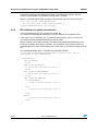
5
Designing an application using the SimpleMAC Library APIs
Designing an application using the SimpleMAC
Library APIs
This section provides information and code examples on how to design and implement a
SimpleMAC application.
The following functions are described:
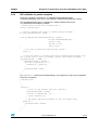
5.1
●
Initialization
●
Configuring the radio
●
Transmitting packets and managing transmit callbacks
●
Enabling/disabling SFD event notifications
●
Receiving packets and managing reception callbacks
●
Configuring the coordinator filter mode
●
Using AES security features
●
Miscellaneous: energy detection, packet trace, CCA assessment.
Initialization
The following steps are required before starting to use the SimpleMAC library APIs:
1.
Initialize the HAL layer.
2.
Seed the random number generator.
3.
Enable the interrupts.
4.
Initialize the serial communication channel.
5.
Perform one-time radio initialization and calibration (radio analog module, digital
baseband and MAC) and leave the radio in the specified default mode (on or off).
The following pseudocode example illustrates the required initialization steps:
/* include library header file */
#include "include/phy-library.h"
void main(void)
{
uint32_t seed;
StStatus status;
/* Initialization phase */
.........
/* seed random number generator */
ST_RadioGetRandomNumbers((uint16_t *)&seed, 2);
halCommonSeedRandom(seed);
/* init serial */
/* Initialize serial interface */
..........
/* Init radio in powered up mode */
Doc ID 16995 Rev 10
39/54
Designing an application using the SimpleMAC Library APIs
UM0893
assert(ST_RadioInit(ST_RADIO_POWER_MODE_RX_ON)==ST_SUCCESS);
while(1)
{
/* Simple MAC application specific steps */
}
}
5.2
Configuring the radio
5.2.1
Radio sleep and wakeup
Call ST_RadioSleep and ST_RadioWake APIs to turn the radio off and on,
respectively:
/* Turning off the radio */
ST_RadioSleep();
/* Turning on the radio */
ST_RadioWake();
5.2.2
Calibrating the radio
The radio needs to be recalibrated to ensure the same performance as environmental
conditions change (temperature, etc.).
The following pseudocode example illustrates the required calibration steps:
void main(void)
{
/* Initialization steps */
...
...
while(1)
{
/* Periodically check if radio calibration conditions
occur (due to temperature change)*/
if (ST_RadioCheckRadio() == TRUE)
{
/* Perform necessary recalibration to counteract the
effects of temperature changes since the last
calibration */
ST_RadioCalibrateCurrentChannel();
}
}
}
40/54
Doc ID 16995 Rev 10
UM0893
5.2.3
Designing an application using the SimpleMAC Library APIs
Setting radio channel, power level and power mode
Before starting transmitting or receiving a packet, select the radio channel and configure the
transmit power and transmit power mode.
Pseudocode example for setting the radio channel
uint8_t channel = USER_CHANNEL;
/* Set radio channel */
ST_RadioSetChannel(channel);
Default radio channel is 11. The radio channel ranges between 11 and 26. The first time a
channel is selected, all radio parameters are calibrated for this channel. This full calibration
process can take up to 200 ms. Subsequent calls to ST_RadioSetChannel() with the same
channel take less time (around 10 ms) because the values are retrieved from the Flash
memory tokens.
Pseudocode example for setting the radio transmit power
int8_t power = USER_TX_POWER;
/* Set radio transmit power level */
ST_RadioSetPower(power);
Default transmit power level is 3 dBm. The radio power ranges from -43 to 8 dBm. The
ST_RadioSetPower() function can set the power level to a value other that the one specified
in the power parameter, since not all integer power levels are available as lower power
levels. When a specific power level is not available, the next higher power level is used.
Pseudocode example for setting the radio power mode
uint16_t txPowerMode = USER_TX_POWER_MODE;
/* Set radio transmit power mode */
ST_RadioSetPowerMode(txPowerMode);
The txPowerMode parameter can take the following values:
bit 0
0: Normal mode.
1: Boost mode. Selecting the Boost mode increases the Rx sensitivity by
approximately 1 dBm, and the Tx power by approximately 0.5 dBm.
bit 1
0: Enables bidirectional transmit path
1: Enables alternate transmit when using an external power amplifier.
Doc ID 16995 Rev 10
41/54
Designing an application using the SimpleMAC Library APIs
UM0893
5.3
Transmitting packets and managing transmit callbacks
5.3.1
Configuring the radioTransmitConfig variable
Before transmitting a packet, declare a variable, radioTransmitConfig, of
RadioTransmitConfig type. The RadioTransmitConfig type corresponds to a structure
containing the parameters and modes related to the packet transmission features (see
Table 29). It must be initialized prior to calling the packet transmit API.
Table 29.
RadioTransmitConfig members
Member
Description
boolean waitForAck
Wait for ACK if ACK request set in FCF.
boolean checkCca
Backoff and check CCA before transmitting the packet.
uint8_t ccaAttemptMax
Number of CCA attempts before failure. The value ranges from 0 to
5. The default value is 4.
uint8_t backoffExponentMin
Backoff exponent for the initial CCA attempt.The value ranges from 0
to 3. The default value is 3.
uint8_t backoffExponentMax
Backoff exponent for the final CCA attempt(s). The default value is 5.
uint8_t minimumBackoff
Minimum number of backoffs (suggested value is 0).
boolean appendCrc
Append CRC to transmitted packets.
If radioTransmitConfig.checkCca is TRUE, ST_RadioTransmit() performs CSMA-CA
backoffs and CCA verifications before transmitting a packet. Otherwise, it starts the
transmission process immediately. The STM32W108xx only supports CCA mode 1. CSMACA reports busy medium if the energy level expressed in dBm exceeds this threshold.
The related radioTransmitConfig variable can be modified only when no transmit operation is
ongoing.
The pseudocode example below explains how to configure the related radioTransmitConfig
variable:
RadioTransmitConfig radioTransmitConfig = {
TRUE,
// waitForAck;
TRUE,
// checkCca;
4,
// ccaAttemptMax;
3,
// backoffExponentMin;
5,
// backoffExponentMax;
0, //minimumBackoff
TRUE
// appendCrc;
};
5.3.2 Setting and transmitting a packet
The following steps are required to transmit a packet:
1.
42/54
The first field of the packet is the related length. If the radioTransmitConfig.appendCrc
is TRUE the packet length byte must also take into account the two bytes of CRC. A
packet with a two-byte payload is represented in memory as:{0x04, 0x00, 0x01, 0xc0,
0xc1} where 0xc0 and 0xc1 are the CRC bytes generated by hardware.
Doc ID 16995 Rev 10
UM0893
Designing an application using the SimpleMAC Library APIs
2.
The packet has to be configured according to the MAC frame format described in IEEE
802.15.4 general MAC frame format :
a)
Table 30.
Set the packet FCF, the packet source and the destination address mode. Refer to
Table 30 for an example of FCF configuration.
Packet FCF configuration as 0x0821
Bits
[0:2]
Bit 3
Bit 4
Bit 5
Bit 6
Frame
type
Security
enabled
Frame
pending
Ack.
request
IntraPAN
100
0
0
1
0
Bit 7
Bits
[8:9]
Reserved
0
00
Bits
[10:11]
Bits
[14:15]
Destination
Source
addressing Reserved addressing
mode
mode
10
0x21
b)
Bits
[12:13]
00
00
0x08
Specify the packet PAN identifier as well as its short or long addresses, according
to the addressing mode selected on the packet FCF.
The pseudocode below shows an example of configuration and 13-byte packet transmission
(plus 2 bytes for the CRC):
uint8_t txPacket[] = {
0x0f, // packet length including two bytes for the CRC
0x21, // FCF - data frame type, no security, no frame
pending, ack request, no intra
PAN
0x08, // FCF - 16 bits short destination address, no
source pan id and address
0x00, // sequence number
0x12, // destination pan id (lowest byte)
0x23, // destination pan id
(highest byte)
0x02, // destination short address/node id (lowest byte)
0x22, // destination short address/node id (highest byte)
0x12, // packet data
0x34, // packet data
0x56, // packet data
0x78, // packet data
0x9A, // packet data
0xBC
// packet data
};
St_Status status;
/* Sent the txPacket */
status = ST_RadioTransmit(txPacket);
Doc ID 16995 Rev 10
43/54
Designing an application using the SimpleMAC Library APIs
UM0893
If radioTransmitConfig.chechCCA equals TRUE, the CSMA-CA backoff(s) and CCA
check(s) are performed using the default energy level (-75 dBm).
Below is a pseudocode example of energy threshold setting for the CCA assessment:
int8_t ed_cca_value = USER_ED_CCA_VALUE
/* Set the energy level used for CCA assessment */
ST_RadioSetEdCcaThreshold (ed_cca_value);
5.3.3
ISR callbacks for packet transmission
If the transmission process has successfully started, the
ST_RadioTransmitCompleteIsrCallback() is called to indicate the completion status.
If the radio is busy transmitting, the ST_RadioTransmit() function returns an error and
ST_RadioTransmitCompleteIsrCallback() will not be called.
Before sending a new packet, check the ST_RadioTransmitIsrCompleteCallback() status
parameter to decide which action to perform. As an example, retransmit the packet if no
acknowledgment has been received when the packet sent has the FCF ACK request bit set
to 1.
The pseudocode below gives an example of transmit ISR callback:
void ST_RadioTransmitCompleteIsrCallback(St_Status status, uint32_t
sfdSentTime, boolean framePending)
{
switch(status) {
case ST_SUCCESS:
break;
case ST_PHY_TX_CCA_FAIL:
/* Insert here user specific action */
break;
case ST_MAC_NO_ACK_RECEIVED:
/* Insert here user specific action */
break;
case ST_PHY_ACK_RECEIVED:
if (framePending) {
/* Insert here user specific action */
}
else {
/* Insert here user specific action */
}
break;
default:
/* Insert here user specific action */
break;
}
}
44/54
Doc ID 16995 Rev 10
UM0893
Designing an application using the SimpleMAC Library APIs
Note:
The “framePending” parameter is TRUE if the received ACK indicates that a frame is
pending. This is a very important information to notify the sender node that the destination
node has pending data for it.
5.3.4
SFD event
It is possible to be notified of an SFD event (see IEEE 802.15.4 general MAC frame format )
through the ST_RadioSfdSentIsrCallback (uint32_t sfdSentTime) callback.
The SFD event notification is disabled by default. To enable it, call the
ST_RadioEnableSfdSentNotification function:
/* Enable SFD event notification */
ST_RadioEnableSfdSentNotification(TRUE);
Once enabled, an SFD event notification is sent through the related callback:
void ST_RadioSfdSentIsrCallback(uint32_t sfdSentTime)
{
/* user code */
}
5.4
Receiving packets
5.4.1
Configuring radio filters for packet reception
To receive a packet, the radio device filters must have been configured. The following steps
are required to configure radio filters:
1.
Set the radio filtering mode according to the user application targets:
/* Set promiscuous mode: receive any packet on the selected radio channel */
/* Disable address filtering*/
ST_RadioEnableAddressFiltering(FALSE);
/* Turn off automatic acknowledgment */
ST_RadioEnableAutoAck(FALSE);
or
/* Receive packets only on a specific pan id and long or short address
(default configuration )*/
ST_RadioEnableAddressFiltering(TRUE);
2.
Enable/disable the automatic transmission of an acknowledgment on packet reception
(only for packets with FCF acknowledge request bit set to 1). Address filtering must be
enabled for the automatic transmission of acknowledgment packet to occur:
/* Enable automatic packet acknowledgement (default is enabled) */
ST_RadioEnableAutoAck(TRUE);
3.
Enable/disable the discarding of received packets for which a CRC verification has
failed. When this feature is enabled, the library automatically removes the CRC bytes
from the packets that passed the CRC verification:
/* Enable discarding packets which fail CRC (default is enabled) */
Doc ID 16995 Rev 10
45/54
Designing an application using the SimpleMAC Library APIs
UM0893
ST_RadioEnableReceiveCrc(TRUE);
4.
When the address filtering mode is enabled, perform the following actions:
a)
Set the radio PAN identifier:
uint16_t panid = USER_PAN_ID;
/* set the panid for filtering received packets */
ST_RadioSetPanId(panid);
b)
Set the node identifier if the user application requires filtering on the 16-bit short
address (or node identifier):
uint16_t nodeid = USER_NODE_ID;
/*set the nodeid (short address) for filtering received packets*/
ST_RadioSetNodeID(nodeid);
The ST_RadioDataPendingforLongIdIsrCallback and ST_RadioDataPendingforShortIdIsrCallback
callbacks are called by the library when the packet source short or long address has been
received. The library sets the frame pending bit in the outgoing acknowledgment only if the
related callback returns TRUE. The user callback implementation must check if the
receiving node has pending data for the detected sender source. This can be done by
searching the source address in a lookup table containing the sender addresses for which
there are data pending, and returning TRUE if there is pending data, and FALSE otherwise.
It is critical that these callback functions complete as quickly as possible, to ensure that the
frame pending bit is set before the acknowledgment is sent back by the library. The sender
node will be notified through the transmit callback that the frame pending bit has been
received in the acknowledgment frame. The pseudocode below gives an example of the two
callbacks:
boolean ST_RadioDataPendingShortIdIsrCallback(uint16_t shortId)
{
/* Verify there are pending data for the sender node:
look for the packet short address in a application table …>
*/
if <pending data>
return TRUE;
else
return FALSE;
}
boolean ST_RadioDataPendingLongIdIsrCallback(uint8_t* longId)
{
/* Verify there are pending data for the sender node:
look for the packet long address in an application table …>
*/
if <pending data>
return TRUE;
else
return FALSE;
}
46/54
Doc ID 16995 Rev 10
UM0893
5.4.2
Designing an application using the SimpleMAC Library APIs
ISR callbacks for packet reception
Each time a packet is received, the ST_RadioReceiveIsrCallback(packet,
ackFramePendingSet, time, errors, rssi) callback is automatically called by the library.
The pseudocode below gives an example of a simple implementation of the
ST_RadioReceiveIsrCallback() callback:
/* buffer where storing the received packet */
uint8_t rxPacket[128];
/* flag for checking that there’s a packet being processed */
boolean packetReceived = FALSE;
void ST_RadioReceiveIsrCallback(uint8_t *packet,
boolean ackFramePendingSet,
uint32_t time,
uint16_t errors,
int8_t rssi)
{
/* note this is executed from interrupt context */
uint8_t i;
/* Copy the packet to a buffer that can be accessed from the main loop.
Don't do the copy if there is already a packet there being processed
(packetReceived
= TRUE) */
if(packetReceived == FALSE) {
for(i=0; i<=packet[0]; i++) {
rxPacket[i] = packet[i];
}
packetReceived = TRUE;
}
}
The rxpacket[] will be processed depending on the application target (see pseudocode
below for an example):
void main(void)
{
...
...
while(1) {
/* print out any packets that were received */
if(packetReceived == TRUE) {
for(i=0; i<=rxPacket[0]; i++) {
<print rxPacket[i]>;
}
/* The packet has been processed, so free the single entry
queue up */
packetReceived = FALSE;
}
}
}
Doc ID 16995 Rev 10
47/54
Designing an application using the SimpleMAC Library APIs
5.5
UM0893
Configuring the coordinator filter mode
The IEEE 802.15.4 standard supports the coordinator filter mode configuration. This feature
allows receiving 802.15.4. data frames which have no destination address: the packets sent
must have a destination addressing mode set to 00b (destination PAN identifier and
destination short address not present). The source PAN identifier must match the
coordinator PAN identifier, and the coordinator has to enable address filtering and set the
same PAN identifier used for filtering the received packets.
Note:
A node which is not a coordinator will not receive these packets.
Call the related APIs to enable the coordinator feature:
/* Enable coordinator feature (default is disabled)*/
ST_RadioSetCoordinator(TRUE).
Follow a pseudocode example showing a packet configured to be sent to a node with
coordinator feature enabled and source pan id 0x2311:
uint8_t txPacket[] = {
0x08, // packet length including two bytes for the CRC
0x21, // FCF - data frame type, no security, no frame
pending, ack request, no intra
PAN
0xc0, // FCF - no destination address mode (only source pan id)
0x00, // sequence number
0x11, // source pan id (lowest byte)
0x23, // source pan id (highest byte)
0x71
// packet data
};
The txpacket[] FCF field is configured as follows:
Table 31.
FCF field of the packet sent to a coordinator node
Bits [0:2]
Bit 3
Bit 4
Bit 5
Bit 6
Frame type
Security
enabled
Frame
pending
Ack.
request
Intra-PAN
100
0
0
1
0
Bit 7
Reserved
0
0x21
48/54
Bits
[8:9]
00
Bits
[10:11]
Bits
[12:13]
Destination
Source
addressing Reserved addressing
mode
mode
00
00
0xc0 (or 0x80)
Doc ID 16995 Rev 10
Bits
[14:15]
11 (or 10)
UM0893
5.6
Designing an application using the SimpleMAC Library APIs
Radio AES security
Refer to the pseudocode below for an example of how to encrypt a block of data using an
encryption key:
/* pointer to 128 bits of key data */
uint8_t key[128] = USER_KEY;
uint8_t block[128];
<Set the block of data>
...
/* Set the AES key */
ST_AesSetKey(key);
/* Encrypts the 128 ‘block’ with the ‘key’ previously configured.
The resulting encrypted data are stored at the same ‘block’
data.
*/
ST_AesEncrypt(block);
5.7
Radio MAC timer
The MAC timer is 20-bit long. Each LSB tick represents 1 µs, and the MAC timer rolls over to
zero approximately once every second. The MAC timer starts operating in free running
mode when ST_RadioInit() is called. To retrieve the MAC timer value, call the
ST_RadioGetMacTimer() API as shown below:
uint32_t mac_timer ;
/* Returns an instantaneous reading of the free-running MAC timer*/
mac_timer =ST_RadioGetMacTimer();
Note:
It is possible to enable/disable a MAC timer compare event
(ST_RadioEnableMacTimerCompare(enable) and to set the related reference compare
value (ST_RadioSetMacTimerCompare(compare_value)).
The ST_RadioMacTimerCompareIsrCallback() callback will be called by the library when a
MAC timer comparison event occurs.
5.8
Other radio features
5.8.1
Radio energy detection
To read the average energy level calculated over the previous eight symbol periods
(128 µs), call the ST_RadioEnergyDetection() API:
int8_t energy_level;
/* get the energy level on the selected radio channel */
energy_level
Note:
= ST_RadioEnergyDetection()
ST_RadioEnergyDetection() returns the chip sensitivity limits (e.g. -97 dBm up to
approximately -25 dBm).
Doc ID 16995 Rev 10
49/54
Designing an application using the SimpleMAC Library APIs
5.8.2
UM0893
Radio CCA
To read the current status (clear or busy) of the selected channel, call the
ST_RadioChannelIsClear API:
boolean channel_status;
/* Get the channel status (clear or busy) */
channel_status = ST_RadioChannelIsClear();
5.8.3
Radio packet trace interface (PTI)
The STM32W108xx includes a packet trace interface (PTI) module which performs robust
packet-based debugging. The PTI lines (PTI_EN, PTI_DATA on GPIO[4:5]) allow accessing
all the received radio packets in a non-intrusive way.
To enable PTI, call the ST_RadioEnablePacketTrace API:
/* enable packet trace interface (default is enabled) */
ST_RadioEnablePacketTrace(TRUE);
To read the current packet trace status (enabled or disabled), call the
ST_RadioPacketTraceEnabled API, as shown below:
boolean packet_trace_status;
packet_trace_status = ST_RadioPacketTraceEnabled();
5.8.4
Send a tone or a carrier wave
The SimpleMAC library provides some APIs which allow performing demodulated carrier
wave (“tone”) transmission or modulated carrier wave transmission on the current channel.
These APIs can be used to test scenarios such as transmit power level measurement.
To start/stop a demodulated carrier wave (“tone”) transmission, call the following APIs:
/* Start sending a tone */
ST_RadioStartTransmitTone()
/* Stop the tone transmission */
ST_RadioStopTransmitTone(void);
To start/stop a modulated carrier wave transmission, call the following APIs:
/* Start sending a carrier wave */
ST_RadioStartTransmitStream()
/* Stop modulated carrier wave transmission */
ST_RadioStopTransmitStream(void);
50/54
Doc ID 16995 Rev 10
UM0893
6
References
References
Table 32.
List of references
Title
Content
IEEE 802.15.4 standard specification
IEEE 802.15.4 standard description
STM32W108 SimpleMAC library APIs
documentation(1)
HTML document describing the SimpleMAC library APIs
1. This HTML file is provided within the SimpleMAC library.
7
List of acronyms
Table 33.
List of acronyms
Term
Meaning
ACK
Acknowledgment
API
Application programming interfaces
CCA
Clear channel assessment
CSMA-CA
Carrier sense multiple access with collision avoidance
FCF
Frame control field
FCS
Frame check sequence
MAC
Medium access control
MFR
MAC footer
MHR
MAC header
PAN
Personal area network
PHY
Physical layer
PHR
PHY header
PSDU
PHY service data unit
RSSI
Received signal strength indication
SFD
Start-of-frame delimiter
SHR
Synchronization header
Doc ID 16995 Rev 10
51/54
Revision history
8
UM0893
Revision history
Table 34.
Document revision history
Date
Revision
12-Feb-2010
1
Initial release.
21-Apr-2010
2
Updated API prefixes in Section 3.3: SimpleMAC library API naming
conventions.
Updated Section 4.1: SimpleMAC sample demonstration application.
Modified sample image and removed Note 1 in Section 4.1.9.
Section 4.1.9: changed Figure 9, Figure 10, Figure 11, and Figure 12;
updated Table 12 and Running a planet application on the application
board.
Removed section 4.1.3 Limitations, as well as Limitations in
Section 4.4.
Updated function name and radio power range in Pseudocode example
for setting the radio transmit power.
Updated function name in Pseudocode example for setting the radio
power mode.
Updated structure and variable name in Section 5.3.1 and
Section 5.3.2.
Function names updated in Section 5.3.3, Section 5.3.4, Section 5.4.1,
Section 5.4.2, Section 5.7, Section 5.8.3.
Updated whole Section 5.8.4.
30-Jul-2010
3
Added Section 4.5: SimpleMAC OTA bootloader demonstration
application and Section 4.6: SimpleMAC nodetest application.
Reviewed initialization steps in Section 5.1: Initialization.
25-Aug-2010
4
Reviewed bootloader name as iap_bootloader.s37.
Reviewed bootloader_demo running steps.
14-Feb-2011
5
Added reference to STM32W108 application boards and removed
reference to MB851 board.
16-Mar-2011
6
Added support for STM32W108xx kits.
12-May-2011
7
Added Section 4.4: SimpleMAC mouse demonstration application
8
Changes derived from SimpleMAC 1.1.0 release
Added STM32W108C8, STM32W108CZ and STM32W108CC
Updated Section 4.1: SimpleMAC sample demonstration application on
page 16
Updated Section 4.3: SimpleMAC talk demonstration application on
page 29
Updated Section 4.4: SimpleMAC mouse demonstration application on
page 32
Updated Section 4.5: SimpleMAC OTA bootloader demonstration
application on page 34
16-Sep-2011
52/54
Changes
Doc ID 16995 Rev 10
UM0893
Revision history
Date
22-Nov-2011
31-Aug-2012
Revision
Changes
9
Minor text edits: STM32W108xx in Introduction
The radio power ranges from -43 to 8 dBm on Pseudocode example for
setting the radio transmit power on page 41
Add uint8_t minimumBackoff to Table 29: RadioTransmitConfig
members on page 42
10
Updated to adapt to SimpleMAC release 2.0.0:
Updated Table 6, Table 14, Table 19 and Table 24, Boards supported
Added Section 4.2: SimpleMAC PC sun GUI application
Edited pseudocodes in Section 5
Doc ID 16995 Rev 10
53/54
UM0893
Please Read Carefully:
Information in this document is provided solely in connection with ST products. STMicroelectronics NV and its subsidiaries (“ST”) reserve the
right to make changes, corrections, modifications or improvements, to this document, and the products and services described herein at any
time, without notice.
All ST products are sold pursuant to ST’s terms and conditions of sale.
Purchasers are solely responsible for the choice, selection and use of the ST products and services described herein, and ST assumes no
liability whatsoever relating to the choice, selection or use of the ST products and services described herein.
No license, express or implied, by estoppel or otherwise, to any intellectual property rights is granted under this document. If any part of this
document refers to any third party products or services it shall not be deemed a license grant by ST for the use of such third party products
or services, or any intellectual property contained therein or considered as a warranty covering the use in any manner whatsoever of such
third party products or services or any intellectual property contained therein.
UNLESS OTHERWISE SET FORTH IN ST’S TERMS AND CONDITIONS OF SALE ST DISCLAIMS ANY EXPRESS OR IMPLIED
WARRANTY WITH RESPECT TO THE USE AND/OR SALE OF ST PRODUCTS INCLUDING WITHOUT LIMITATION IMPLIED
WARRANTIES OF MERCHANTABILITY, FITNESS FOR A PARTICULAR PURPOSE (AND THEIR EQUIVALENTS UNDER THE LAWS
OF ANY JURISDICTION), OR INFRINGEMENT OF ANY PATENT, COPYRIGHT OR OTHER INTELLECTUAL PROPERTY RIGHT.
UNLESS EXPRESSLY APPROVED IN WRITING BY TWO AUTHORIZED ST REPRESENTATIVES, ST PRODUCTS ARE NOT
RECOMMENDED, AUTHORIZED OR WARRANTED FOR USE IN MILITARY, AIR CRAFT, SPACE, LIFE SAVING, OR LIFE SUSTAINING
APPLICATIONS, NOR IN PRODUCTS OR SYSTEMS WHERE FAILURE OR MALFUNCTION MAY RESULT IN PERSONAL INJURY,
DEATH, OR SEVERE PROPERTY OR ENVIRONMENTAL DAMAGE. ST PRODUCTS WHICH ARE NOT SPECIFIED AS "AUTOMOTIVE
GRADE" MAY ONLY BE USED IN AUTOMOTIVE APPLICATIONS AT USER’S OWN RISK.
Resale of ST products with provisions different from the statements and/or technical features set forth in this document shall immediately void
any warranty granted by ST for the ST product or service described herein and shall not create or extend in any manner whatsoever, any
liability of ST.
ST and the ST logo are trademarks or registered trademarks of ST in various countries.
Information in this document supersedes and replaces all information previously supplied.
The ST logo is a registered trademark of STMicroelectronics. All other names are the property of their respective owners.
© 2012 STMicroelectronics - All rights reserved
STMicroelectronics group of companies
Australia - Belgium - Brazil - Canada - China - Czech Republic - Finland - France - Germany - Hong Kong - India - Israel - Italy - Japan Malaysia - Malta - Morocco - Philippines - Singapore - Spain - Sweden - Switzerland - United Kingdom - United States of America
www.st.com
54/54
Doc ID 16995 Rev 10