1
Frequency Agile® 900MHz
16 Point Receiver Expander
for Radionics 2000 Series Control Panels
Installation Instructions
02793
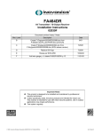
Product Description
The FA422 is a 900MHz receiver that functions as a wireless point expander. This Expander
can process information from as many as 16 Inovonics transmitters and communicate their
individual point status to a specific class of Radionics control panels. The FA422 can
interface to all 2000 Series Control Panels that have wireless point expansion capability by
way of Radionics’ proprietary MonoBus. All Inovonics FA Series Security Transmitters and
Repeaters are compatible with the FA422. This product has been designed for quick and
easy indoor installation.
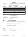
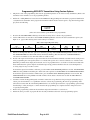
FIGURE 1
FA422 Housing
Housing Pry Slots
de LED
alid LED
ply LED
DECODE
900 MHz
For
VALID
16
POINT
EXPANDER
2000 SERIES CONTROL PANELS
REPLY
By
Frequency Agile ®
FA422 RECEIVE
Housing Pry Slots
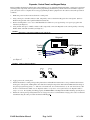
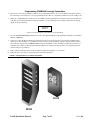
FIGURE 2
FA422 Programming and Diagnostic Components
Mono-Bus Address Jumper
Reply LED
ADDRESS
7
8
DATA
To
Control Panel
DECODE
AUX+
VALID
AUX—
REPLY
2
STD
SECURITY
N/0
W
SELECTED
EOL
3
STD
Security LED
1
N/C
COMMAND
NO
ALT ARMING
SELECTED
TRANSMITTER CUSTOM
TYPE
OPTIONS
EXT'D SPVN
WINDOW
TAMPER
Programming header
LIT-FA422-Install
© 1999 InovonicsWireless Corporation
02793.FM
Compatibility
Control Panels:
All Radionics 2000 Series Control Panels with wireless point expansion capability
(includes D2212, D2212B, and D2412U)
Most FA Series Security transmitters.
Security Transmitters:
Table 1: Security Transmitters Compatible with the FA422
Transmitter
Model Number
Transmitter
Description
Transmitter
Model Number
Transmitter
Description
FA200
Universal (Door/Window)
FA206I/S
FA200W
Universal Wide-Gap
FA206DS
Inovonics and Sentrol PIRs
Detection Systems PIR
FA210
Reduced-size Universal
FA207
Glassbreak Detector
FA210W
Reduced-size Universal Wide-Gap
FA209
Billtrap
FA210M
Reduced-size Universal for Momentary Switch
FA216L/H
Low and High Temperature Detectors
FA210DBN
Reduced-size Universal with Switch De-bounce
FA525
Repeater
FA250
High-Power Universal
FA536
Locator
FA201
Smoke detectors
FA570
High-Power Indoor Repeater
Pendants
FA575
High-Power Outdoor Repeater
FA202
FA203S/D
FA205S/D
FA204
FA223S
Security transmitters can also be made to arm and disarm a system.
(See Alt Arming information, page8.)
All FA Series Security repeaters
FA113 Three-function Command transmitter
FA100 Four-function Command transmitter
(Note: The FA130 Wireless Keypad is NOT compatible with Radionics 2000 Series
Control Panels.)
Security Repeaters:
Command Transmitters
(system arming/disarming
and special functions)
CAUTION:
If an FA100 is used with the Expander, the C key on the Radionics keypad(s) must not be
programmed for an emergency function.
Pressing the * key on the FA100 one time has the same effect on a 2000 series panel system as pressing
the C key on a Radionics keypad two times.
If the C key is programmed to perform an emergency function (like calling the police), accidentally
pressing the * key on theFA100 one time could activate the emergency function.
If it is desired to program the C key for an emergency function and have a Command transmitter
activate this function, use the FA113. The two * keys on the FA113 must be pressed simultaneously to
have the same effect as pressing the C key two times.
Specifications
Housing dimensions:
Weight:
Power requirement:
Current draw:
Receiver type:
Operating Environment:
FA422 Installation Manual
6.38" x 3.60" x 1.10"
5.3 oz.
10.2VDC-13.9VDC (provided by external power supply or by panel via MonoBus)
45mA typical, 60mA maximum
frequency-hopping spread-spectru
32°-122°F (0-50°C), up to 95% relative humidity (non-condensing)
Page 2 of 11
02793.FM
Expander, Control Panel, and Keypad Setup
Before installing the Expander and wireless point transmitters, it is recommended that the Expander, control panel, and a hardwired keypad be temporarily wired together. Panel programming should then be performed and each transmitter assigned a
point code. (It is easier to complete the necessary programming if all the equipment is in the same location.) The procedure is
as follows:
1.
Make sure power has been removed from the control panel.
2.
Using a short piece of multi-conductor cable, temporarily connect a hard-wired keypad to the control panel. (Refer to
Radionics keypad and control panel installation instructions.)
Remove the Expander’s cover. Use a small flat-bladed screwdriver to gently pry housing cover open at pry point slots
indicated. (See Figu re1.)
Using another short piece of multi-conductor cable, temporarily connect the Expander to the control panel by connecting
DATA, AUX+ and AUX- terminals. (See Figu re3.)
3.
4.
FIGURE 3
Expander, Control Panel and Keypad Connections
Keypad
Control
Panel
FA422 Expander
ADDRESS
7
8
Data
Aux +
Aux –
5.
VALID
AUX—
REPLY
Address Selection Header
ADDRESS
ADDRESS
7
7
8
Address = 7
8.
DECODE
AUX+
Set up the Expander to respond to MonoBus address 7 or 8 by moving its address jumper.
(See Figure 4.)
FIGURE 4
6.
7.
DATA
8
Address = 8
Apply power to the control panel.
Follow the Radionics control panel operating instructions and installation instructions to set up communication between
the keypad, control panel, and Expander. Note that when setting the Supervision Interval in the RF Parameters Group of
the panel’s program entry guide, a "1" indicates a 4-hour interval, not a 24-hour interval. (A "0" selection, however, still
means a 12-hour interval.) Make sure the Expander address set-up at the control panel matches the Expander address
jumper selection. If everything is working properly, the REPLY LED on the Expander should be flashing. (See Fi gure2.)
Follow the control panel operating instructions to assign point codes to each transmitter. Assign point codes to Command
transmitters using the same procedure described for RF keypads FA422 Installation Manual
Page 3 of 11
02793.FM
Transmitter Programming
The Expander can program three different types of Inovonics transmitters:
•
SECURITY transmitters are devices like universal transmitters (door/window sensors), pendants, wireless smoke
detectors, and wireless PIRs that send alarm, restoral, and check-in signals.
•
COMMAND transmitters are devices that arm and disarm a system and send programmable command signals (such
as “Call the police,” or “Open the garage door”) to the control panel.
•
ALT ARMING (Alternative Arming) transmitters are Security transmitters that are given the capability to arm and
disarm a system (like a Command transmitter). When a Security transmitter is programmed as ALT ARMING, its
alarm signal is interpreted by the Expander and sent to the panel as a system arming signal, and its restoral signal is
interpreted and sent as a system disarming signal. Unlike Command transmitters, Alt Arming transmitters can be
assigned point codes that monitor their check-in signals, tamper condition, and battery condition.
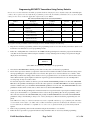
To set up the Expander for programming transmitters, locate the programming cable supplied with the Expander and plug one
end into the Expander’s programming header. (See F igure5.) When all transmitters have been programmed, remove the cable
from the Expander programming header, store the cable in the open area to the left of the Expander’s printed circuit board, and
put the Expander’s cover back on.
FIGURE 5
Expander Programming Detail
N/C
1
STD
2
COMMAND
Security LED
SECURITY
N/0
SELECTED
W
EOL
3
STD
NO
ALT ARMING
SELECTED
TRANSMITTER CUSTOM
TYPE
OPTIONS
EXT'D SPVN
WINDOW
TAMPER
Programming header
FA422 Installation Manual
Page 4 of 11
02793.FM
Programming SECURITY Transmitters Using Factory Defaults
In most cases, Security transmitters should be programmed without changing the factory default settings (like Normally Open
contacts). An exception to the rule might be the programming of universal (door/window) transmitters. To see if factory default
settings for these devices match the application requirements, refer to Table 2.
Table 2: Factory Default Settings for Selected Security Transmitters
Transmitter Model
Number
Transmitter
Description-
External Contacts
Condition
Internal Contacts
Activated?
Expects
EOL Resistor?
FA200
Universal (Door/Window)
Normally Closed
No
FA200W
Universal Wide-Gap
Normally Open
Yes
No
No
FA210
Reduced-Size
Universal
Normally Closed
No
No
FA210W
Reduced-Size
Universal Wide-Gap
Normally Open
Yes
No
FA210M
Reduced-Size Universal
for Momentary Switch
Normally Open
No
No
FA210DBN
Reduced-Size Universal
with Switch De-Bounce
Normally Closed
No
No
FA250
High-Power Universal
Normally Open
No
No
To program a Security transmitter without changing its factory default settings do the following:
1.
Plug the free end of the programming cable into the programming header on one of the Security transmitters. (Refer to the
transmitter’s user manual to access its programming header.)
2.
Follow the "Adding RF Points" instructions in the D2000 Series Keypad Diagnostics manual to program an identification
code (ID) into the transmitter while leaving the transmitter’s factory default options unchanged. Stop when the keypad
display shows the following:
ACTIVATE
POINT nn
(where nn is the transmitter point number to be programmed)
3.
4.
Note that the SECURITY LED is flashing to show that a Security device is about to be programmed.
Decide if the supervision window (or supervision interval) for the transmitter should be extended from the setting chosen
when programming the control panel (either 4 or 12 hours). The options are to extend to 96 hours or to “infinite” hours.
(Extending to infinite hours simply means that the receiver is programmed not to ever look for check-ins from that transmitter.) Extended time options might be useful when supervising pendant transmitters that are out of the Expander’s
receiving range for days or weeks at a time.
To extend the supervision window to 96 hours, press the EXT’D SPVN WINDOW pushbutton one time. The SELECTED
LED above this pushbutton should begin to flash at the same rapid rate as the SECURITY LED. To extend the supervision
window to infinite hours, press the EXT’D SPVN WINDOW pushbutton one more time. The SELECTED LED above this
pushbutton should continue to flash, but at a much slower rate than the SECURITY LED.
5.
6.
7.
Continue to follow the Keypad Diagnostics manual’s instructions except that instead of pressing the transmitter’s tamper
switch, press the transmitter’s reset pushbutton switch to activate the programming. (Be sure the programming cable i
still connected.) Note that the SECURITY LED (and possibly the SELECTED LED above the EXT’D SPVN WINDOW
pushbutton) changes from flashing to always-on or “solid”. (See Fig ure5.) This shows that the programming was completed.
If the LEDs do not change to solid, the transmitter may not be compatible with this type of programming. The transmitter
version must be 1.80 or higher. (See label on box or label on transmitter printed circuit board.) If the transmitter version
is lower than 1.80, the transmitter is compatible in every other way except that it must be programmed using Custom
Options.
Remove the programming cable from the transmitter and put the transmitter’s cover back on.
Follow the above procedure to program all other Security transmitters that can use factory default programming.
FA422 Installation Manual
Page 5 of 11
02793.FM
Programming SECURITY Transmitters Using Custom Options
1.
Plug the free end of the programming cable into the programming header on one of the Security transmitters. (Refer to the
transmitter’s user manual to access its programming header.)
2.
Follow the "Adding RF Points" instructions in the D2000 Series Keypad Diagnostics manual to program an identification
code (ID) into the transmitter and to program the transmitter with the desired custom options. Stop when the keypad display shows the following:
ACTIVATE
POINT nn
(where nn is the transmitter point number to be programmed)
3.
4.
Note that the SECURITY LED is flashing to show that a Security device is about to be programmed.
Set the DIP switches located above the CUSTOM OPTIONS pushbutton switch to the desired transmitter options. (See
Figur e5 on page4.) The meaning of the switch settings is as follows:
Table 3: Custom Option Dip switch settings
Switch 1
5.
6.
Switch 2
Switch 3
N/C
N/O
STD
W
STD
EOL
Normally Closed
Normally Open
No Internal Contacts
Internal
Contacts
No EOL
Resistor
EOL
Resistor
Indicate to the Expander that these options are desired by pressing theCUSTOM OPTIONS pushbutton switch one time.
The SELECTED LED beneath the DIP switches should start flashing. (Note that whenever CUSTOM OPTIONS is
selected for a transmitter, its check-in time will be set to 60 seconds.)
Decide if the supervision window (or supervision interval) for the transmitter should be extended from the setting chosen
when programming the control panel (either 4 or 12 hours). The options are to extend to 96 hours or to “infinite” hours.
(Extending to infinite hours simply means that the receiver is programmed not to ever look for check-ins from that transmitter.) Extended time options might be useful when supervising pendant transmitters that are out of the Expander’s
receiving range for days or weeks at a time.
To extend the supervision window to 96 hours, press the EXT’D SPVN WINDOW pushbutton one time. The SELECTED
LED above this pushbutton should begin to flash at the same rapid rate as theSECURITY and CUSTOM OPTIONS LEDs.
To extend the supervision window to infinite hours, press the EXT’D SPVN WINDOW pushbutton one more time. The
SELECTED LED above this pushbutton should continue to flash, but at a much slower rate than the SECURITY and
CUSTOM OPTIONS LEDs.
7.
8.
9.
Continue to follow the Keypad Diagnostics manual’s instructions except that instead of pressing the transmitter tamper
switch, press the transmitter’s reset pushbutton switch to activate the programming. (Be sure the programming cable i
still connected.) Note that all of the flashing LEDs that have to do with supervision time or programming options change
from flashing to solid. (See Figure 5 .) This shows that the programming was completed and the changes have been
accepted by the Expander.
Remove the programming cable from the transmitter and put the transmitter’s cover back on.
Follow the above procedure to program all other Security transmitters that need custom programming options.
FA422 Installation Manual
Page 6 of 11
02793.FM
Programming COMMAND (Arming) Transmitters
1.
Plug the free end of the programming cable into the programming header on one of the Command transmitters. (Refer to
the transmitter’s user manual to access its programming header.) The two compatible transmitters are shown in Fig u re6.
2.
Follow the "Adding RF Points" instructions in the D2000 Series Keypad Diagnostics manual to program an identification
code (ID) into the transmitter while leaving the transmitter’s factory default options unchanged. Stop when the keypad
display shows the following:
ACTIVATE
POINT nn
(where nn is the transmitter point number to be programmed)
3.
4.
5.
6.
Press the TRANSMITTER TYPE pushbutton one time. The flashing LED above this pushbutton should move from SECURITY to COMMAND.
Continue to follow the Keypad Diagnostics manual’s instructions except that instead of pressing the transmitter tamper
switch, press the transmitter’s reset pushbutton switch to activate the programming. (Be sure the programming cable is
still connected.) Note that the COMMAND LED changes from flashing to solid. (See Figu re5.) This shows that the programming was completed. (Note that Command transmitters are unsupervised and, therefore, no extended supervision
window changes are permitted.)
Remove the programming cable from the transmitter and put the transmitter’s cover back on.
Follow the above procedure to program all other Command transmitters.
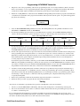
FIGURE 6
FA100 and FA113 Command Transmitter
FA 1 1 3
FA 1 0 0
FA422 Installation Manual
Page 7 of 11
02793.FM
Programming ALT ARMING Transmitter
1.
Plug the free end of the programming cable into the programming header on a Security transmitters. (Refer to the transmitter’s user manual to access its programming header.) When programming is completed, this transmitter will arm the
system when its alarm signal is transmitted, and disarm the system when its restoral signal is transmitted.
2.
Follow the "Adding RF Points" instructions in the D2000 Series Keypad Diagnostics manual to program an identification
code (ID) into the transmitter and to program the transmitter with any desired custom options. Stop when the keypad display shows the following:
ACTIVATE
POINT nn
(where nn is the transmitter point number to be programmed)
3.
4.
Press the TRANSMITTER TYPE pushbutton two times. The flashing LED above this pushbutton should move from
SECURITY to COMMAND and then to ALT ARMING.
If custom programming options are desired, set the DIP switches located above the CUSTOM OPTIONS pushbutton
switch to the desired transmitter options. (See Figur e5 on page 4.) The meaning of the switch settings is as follows:
Table 4: Custom Option DIP switch settings
Switch 1
5.
6.
Switch 2
Switch 3
N/C
N/O
STD
W
STD
EOL
Normally Closed
Normally Open
No Internal Contacts
Internal
Contacts
No EOL
Resistor
EOL
Resistor
If custom programming options are desired, indicate this desire to the Expander by pressing the CUSTOM OPTIONS
pushbutton switch one time. The SELECTED LED beneath the DIP switches should start flashing. (Note that whenever
CUSTOM OPTIONS is selected for a transmitter, its check-in time will be set to 60 seconds.)
Decide if the supervision window (or supervision interval) for the transmitter should be extended from the setting chosen
when programming the control panel (either 4 or 12 hours). The options are to extend to 96 hours or to “infinite” hours.
(Extending to infinite hours simply means that the receiver is programmed not to ever look for check-ins from that transmitter.) Extended time options might be useful when supervising pendant transmitters that are out of the Expander’s
receiving range for days or weeks at a time.
To extend the supervision window to 96 hours, press the EXT’D SPVN WINDOW pushbutton one time. The SELECTED
LED above this pushbutton should begin to flash at the same rapid rate as the ALT ARMING LED. To extend the supervision window to infinite hours, press the EXT’D SPVN WINDOW pushbutton one more time. The SELECTED LED above
this pushbutton should continue to flash, but at a much slower rate than the ALT ARMING LED.
7.
8.
9.
Continue to follow the Keypad Diagnostics manual’s instructions except that instead of pressing the transmitter tamper
switch, press the transmitter’s reset pushbutton switch to activate the programming. (Be sure the programming cable is
still connected.) Note that all of the flashing LEDs that have to do with supervision time or programming options change
from flashing to solid. (See Figure 5 .) This shows that the programming was completed and the changes have been
accepted by the Expander.
Remove the programming cable from the transmitter and put the transmitter’s cover back on.
Follow the above procedure to program all other Alt Arming transmitters.
Testing
After at least one transmitter is programmed, the operation of the Expander can be tested as follows:
1.
Check to see that the REPLY LED is still flashing. This shows that the Expander is communicating with the panel.
2.
Put one of the transmitters into its alarm or command condition. This should cause the panel and keypad to give the correct alarm or command response.
It is recommended that all transmitters be tested before installation. If a particular transmitter does not give the correct
response, troubleshoot the problem by following the "Point Status" instructions in the D2000 Series Keypad Diagnostic manual and the "Troubleshooting with the Cover Off" instructions in this manual.
FA422 Installation Manual
Page 8 of 11
02793.FM
Installation
1.
Remove power from the control panel.
2.
3.
Remove the temporary cables between the panel and the keypad, and panel and the Expander.
Determine an appropriate indoor location to mount the Expander. (The housing is designed for indoor use only. ) Do not
enclose the Expander in a metal box. To assure peak performance, avoid mounting the Expander on a metal surface or near
large metal objects
Run the cable wiring from the panel to the Expander. Avoid running the wiring next to electrical, telephone, or other data
wiring. Refer to the panel installation instructions to determine maximum cable length and other wiring details
Route the cable wiring into either the side or back of the Expander. If the wiring is routed through the back of the
Expander, use a small side cutter or utility knife to remove the wiring knockout. If the wiring is routed through the side,
lift out the wiring shutter. (See Figure7. )
If DC power is supplied by the panel, connect the cable wires from the panel to the Expander as follows:
4.
5.
6.
Radionics Panel
FA422 Expander
Data
Aux +
Aux –
7.
DATA
AUX +
AUX –
There may be some installations where DC power to the Expander must be supplied by an external DC power supply.
Refer to the panel installation instructions for further details. If DC power is supplied from an external DC power supply,
connect the cable wires from the panel to the Expander as follows:
Radionics Panel
Data
Aux –
FA422 Expander
Power Supply
+
–
DATA
AUX +
AUX –
CAUTION:
Make sure power supply "—"
(negative) terminal is isolated
from earth ground.
8.
Mount the expander to a wall or surface using the supplied hardware. (See F igure7.)
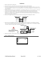
FIGURE 7
FA422 Housing Base
Wiring knockout
Mounting holes
(4 places)
Wiring shutter
FA422 Installation Manual
Page 9 of 11
02793.FM
Troubleshooting
The Expander contains a number of diagnostic LEDs that will aid in troubleshooting system problems. Since some of these
LEDs only are visible with the cover off, this section will be divided into troubleshooting with cover on and troubleshooting
with cover off.
Troubleshooting with the Cover On
Three diagnostic LEDs are visible when the Expander cover is on: DECODE, VALID, and REPLY. The way they help to troubleshoot a problem is as follows:
The REPLY LED shows the status of the communication between the Expander and the control panel. This LED should flash
once each time it responds to a data request from the panel. During normal operation, REPLY should be continually flashing.
REPLY Status
Always Off
Probable Causes
of Problem:
Flashing
Broken cable connection
Normal
Always On
Broken Expander
No power to Expander
Panel communication problem
Expander address not programmed at
panel
Broken Expander
The DECODE LED flashes to show that the Expander is active and listening. If it is not flashing, check to make sure that
power is supplied to the Expander.
The VALID LED shows the status of the successful number of signal decoding attempts of the 900 MHz radio receiver on the
Expander. This LED should flash each time the receiver successfully decodes an incoming signal from an Inovonics transmitter that was programmed into the system. When a transmitter sends an alarm or check-in signal, VALID should start flashing.
VALID Status
Probable Causes
of Problem:
Always Off
Flashing
No power to Expande
Normal
Broken or unprogrammed transmitter(s)
(when a transmitter is activated
or checkin gin
Always On
Transmitter programming problem
Broken Expander
Broken Expander
Troubleshooting with the Cover Off
All three diagnostic LEDs visible with the cover on are also visible with the cover off. Therefore, all troubleshooting techniques discussed in the previous section also apply to this section.
Additional diagnostic LEDs are visible with the Expander cover off. These are the LEDs used for transmitter programming.
They can be used to troubleshoot problems with individual transmitters by allowing the installer to check how it was programmed.
To check how a transmitter was programmed, do the following:
1.
Locate the transmitter’s reset pushbutton. (Refer to the transmitter’s user manual.)
2.
Press the transmitter’s reset pushbutton one time and note which programming LEDs light. (The lighted LEDs will stay on
for a few seconds.) If the wrong LEDs light up, the transmitter had been misprogrammed.
(Note that if the SELECTED LED located beneath the DIP switches is on, this only indicates that the transmitter was programmed with one or more custom options. The current positions of the DIP switches will not necessarily indicate which
options were selected.)
FA422 Installation Manual
Page 10 of 11
02793.FM
Warranty & Disclaimer
Inovonics Wireless Corporation ("Inovonics") warrants its products ("Product" or "Products") to conform to its own specifications and to be free of defects in materials and workmanship under normal
use for a period of twenty-four (24) months from the date of manufacture. Within the warranty period
Inovonics will repair or replace, at its option, all or any part of the warrantied product. Inovonics will
not be responsible for dismantling and/or reinstallation charges. To exercise the warranty, the User
("User", "Installer" or "Consumer") must be given a Return Material Authorization ("RMA") Number
by Inovonics. Details of shipment will be arranged at that time.
This warranty does not apply in cases of improper installation, misuse, failure to follow installation
and operating instructions, alteration, abuse, accident or tampering, and repair by anyone other than
Inovonics.
This warranty is exclusive and expressly in lieu of all other warranties, obligations or liabilities,
whether written, oral, express, or implied, including any warranty of merchantability or fitness for a
particular purpose. Inovonics will not be liable to anyone for any consequential or incidental damages
for breach of this warranty or any other warranties.
This warranty will not be modified, varied or extended. Inovonics does not authorize any person to act
on its behalf to modify, vary or extend this warranty. This warranty will apply to Inovonics Products
only. All other products, accessories or attachments used in conjunction with Inovonics equipment,
including batteries, will be covered solely by their own warranty, if any. Inovonics will not be liable
for any direct, incidental or consequential damage or loss whatsoever, caused by the malfunction of
Product due to products, accessories, or attachments of other manufacturers, including batteries, used
in conjunction with Inovonics Products.
This warranty does not warrant the replacement of batteries that are used to power Inovonics Products.
The User recognizes that a properly installed and maintained security system may only reduce the
risk of events such as burglary, robbery, personal injury and fire. It does not insure or guarantee that
there will be no death, personal damage and/or damage to property as a result. Inovonics does not
claim that the Product may not be compromised and/or circumvented, or that the Product will
prevent any death, personal and/or bodily injury and/or damage to property resulting from
burglary, robbery, fire or otherwise, or that the Product will in all cases provide adequate warning or protection.
Inovonics 3shall have no liability for any death, injury or damage, however incurred, based on a
claim that Inovonics Products failed to function. However, if Inovonics is held liable, directly or
indirectly, for any loss or damage arising under this limited warranty or otherwise, regardless of cause
or origin, Inovonics' maximum liability will not in any case exceed the purchase price of the Product,
which will be fixed as liquidated damages and not as a penalty, and will be the complete and exclusive
remedy against Inovonics.
Warning:The User should follow all installation, operation and maintenance instructions. The
User is strongly advised to conduct Product and systems tests at least once each week. Changes in
environmental conditions, electric or electronic disruptions and tampering, may cause the Product to
not perform as expected.
Warning:Inovonics warrants its Product to the User. The User is responsible for exercising all due
prudence and taking necessary precautions for the safety and protection of lives and property wherever Inovonics Products are installed. Inovonics strongly advises the User to program Products to be
supervised whenever used in applications affecting life safety. Users are warned that unsupervised
devices are subject to undetected failure due to malfunction, battery failure, tampering, or changes in
environment.
FA422 Installation Manual
Page 11 of 11
02793.FM