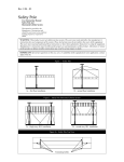
1
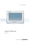
LOGIC INSTRUMENT Fieldbook I1 User's Manual 1 1 About This Manual This User’s Manual provides instruction for when setting up a new Fieldbook I1 device. Latest information and manual versions are available for download on www.logic-instrument.com Bolded or underlined text is used to emphasize the designated information. A Note is used to provide additional information for the device or settings. A caution symbol is used to warn against potential hazards or caution against unsafe practices. A Warning is used to identify immediate hazards for property damage, injury or death. 2 2 Safety Instructions Please read these safety instructions carefully and keep this manual for later reference. Logic Instrument assumes no liability for any and all damages arising from misuse or noncompliance with these guidelines. 1. All cautions and warnings on the equipment should be noted. 2. Never open the device. For safety reason, the equipment should only be opened by qualified service personal. 3. Never pour any liquid into opening: this could cause fire or electrical shock. 4. Make sure the equipment is connected to the power source with the correct voltage, frequency, and ampere. 5. If you use an extension cable with the AC adapter, ensure that the total ampere rating of all products plugged in to the extension cable does not exceed the ampere rating of the extension cable. 6. Do not place anything on the AC adapters power cable and make sure the cable is not located where it can be tripped over or stepped on. 7. Do not cover the AC adaptor as it reduces the cooling 8. Do not use the AC adapter while it is inside the carrying case. 9. Use only the AC adapter, power cord and batteries that are approved for use with the device. 10. Use of other types of battery or AC adapters than suggested by the manufacturer may cause risk of fire or explosion. 11. When disconnecting cables, pull on the connector or on its strain relief loop, not on the cable itself. When pulling out or plugging in the connector, keep it evenly aligned to prevent bending the connector pins. 12. Disconnect the device from the power supply before cleaning. Use a moisture sheet or cloth for cleaning. 13. Caution on use of battery: Use the battery recommended by the manufacturer or the same type of battery installed by the manufacturer. If incorrect battery is used, it may cause explosion or fire hazard. Recycle or discard used batteries according the manufacturer’s instruction or your local authority. 14. Get the equipment checked by a service personnel in any of these cases: o o o Liquid has penetrated the device. The equipment did not worked well or you cannot get it to work according to User’s Guide. The device was dropped and damaged, and there are obvious signs of breakage. Risk of fire and chemical burn if the battery is not handled properly! Do not disassemble, crush, puncture, or short external contacts, or expose the battery to temperatures higher than 60 °C (140 °F). Do not dispose a used battery in water or fire. There is a danger of explosion if the battery is incorrectly replaced. Replace only with same or equivalent type recommended by the manufacturer. Discard used batteries according to the manufacturer’s instructions. 3 2.1 Electrical Hazards 2.1.1 Cleaning / Servicing Always disconnect the Fieldbook I1 from the power source before cleaning or servicing it. 2.1.2 Power Adapter Contact authorized service personnel for repairs. Logic Instrument power cables meet industrial requirements for low-temperature flexibility, UV resistance and oil resistance. Use only supplied power cables from Logic Instrument. If other power cables are used, the following may apply: • The operator is solely responsible for the resulting damage; • All Logic Instrument warranties are void. 2.2 Environmental Hazards Do not use the Fieldbook I1 in locations near flammable gases or vapor. The use of electrical equipment in explosive environments can be dangerous. • Always turn off the device when near a gas station, fuel depot, chemical plant or a place where blasting operations take place. 2.3 Radio Transmissions 2.3.1 Permitted Transmission Power Follow the national regulations for the maximum permitted transmission power. The operator is solely responsible for this type of operation. 2.3.2 Radio Frequency Limited Locations Considering the radio frequency limitation in hospitals and aircraft, the Fieldbook I1 can only be installed with permission. Industrial computers may affect the function of implanted medical devices such as pacemakers and may cause malfunction. 4 3 Regulatory and Certification 3.1 FCC Compliance Statement This equipment has been tested and found to comply with the limits for a Class B digital device, pursuant to part 15 of the FCC Rules. These limits are designed to provide reasonable protection against harmful interference when the equipment is operated in a commercial environment. This equipment generates, uses, and can radiate radio frequency energy and, if not installed and used in accordance with the instruction manual, may cause harmful interference to radio communications. Operation of this equipment in a residential area is likely to cause harmful interference in which case the user will be required to correct the interference at his own expense. However, there is no guarantee that interference will not occur in a particular installation. If this equipment does cause harmful interference to radio or television reception, which can be determined by turning the equipment off and on, the user is encouraged to try to correct the interference by one or more of the following measures: • Reorient or relocate the receiving antenna • Increase the separation between the equipment and receiver • Connect the equipment into an outlet on a circuit different from that to which the receiver is connected • Consult the dealer or an experienced radio / TV technician for help Any changes or modifications not expressly approved by the grantee of this device could void the user’s authority to operate the equipment. This device is operation in 5.15 – 5.25GHz frequency range, then restricted in indoor use only, Outdoor operations in the 5.15 – 5.25GHz is prohibit. This device is slave equipment; the device is not radar detection and not ad-hoc operation in the DFS band. 3.2 Labeling Requirements This device complies with Part 15 of the FCC Rules. Operation is subject to the following two conditions: (1) this device may not cause harmful interference, and (2) this device must accept any interference received, including interference that may cause undesired operation. 3.3 RF Exposure Information (SAR) This device meets the government’s requirements for exposure to radio waves. This device is designed and manufactured not to exceed the emission limits for exposure to radio frequency (RF) energy set by the Federal Communications Commission of the U.S. Government. The exposure standard employs a unit of measurement known as the Specific Absorption Rate, or SAR. The SAR limit set by the FCC is 1.6 W/kg. Tests for SAR are conducted using standard operating positions accepted by the FCC with the EUT transmitting at the specified power level in different channels. The highest SAR value for the device as reported to the FCC is 0.57 W/kg when placed next to the body. 3.4 R&TTE This device complies with the essential requirements of the R&TTE Directive 1999/5/EC. 5 3.5 CE Marking This product has passed the CE test for environmental specifications when shielded cables are used for external wiring. We recommend the use of shielded cables. Please contact your local representative for ordering information. This product has passed the CE test for environmental specifications. Test conditions for passing included the equipment being operated within an industrial enclosure. In order to protect the product from being damaged by ESD (Electrostatic Discharge) and EMI leakage, we strongly recommend the use of CE-compliant industrial enclosure products. 3.6 Europe – EU Declaration of Conformity This device complies with the essential requirements of the R&TTE Directive 1999/5/EC and EMC directive 2004/108/EC. The following test methods have been applied in order to prove presumption of conformity with the essential requirements of the R&TTE Directive 1999/5/EC and EMC directive 2004/108/EC: ØØ EN 55022: 2010 +AC:2011, Class B ØØ EN 61000-3-2:2006 +A2:2009 ØØ EN 61000-3-3:2013 ØØ EN 55024:2010 IEC 61000-4-2 Ed 2.0:2008 IEC 61000-4-3 Ed 3.2:2010 IEC 61000-4-4 Ed 3.0:2012 IEC 61000-4-5 Ed 2.0:2005 IEC 61000-4-6 Ed 4.0:2013 ØØ IEC 61000-4-8 Ed 2.0:2009 IEC 61000-4-11 Ed 2.0:2004 IEC 60950-1 2005 5second Edition) +Am 1:2009 ØØ ØØ ØØ ØØ ØØ ØØ ØØ ØØ EN 300 328:V1.8.1:2012-06 EN 301 489-17:V2. 2.1: 2012-09 EN 301 489-1:V1.9.2 :2011-09 EN 301 489-3 :V1.6.1 :2013-08 EN 301 893 :V1.7.1 :2013-06 EN 300 440-1 :V1.6.1 :2010-08 EN 300 440-2 :V1.4.1 :2010-08 EN 50966 March 2013 & EN 62209-2 Jun 2010 This device is a 2.4GHz wideband transmission system (transceiver), intended for use in all EU member states and EFTA countries - UE countries list BE BG CZ DK DE EE IE EL ES FR HR IT CY LV LT LU HU MT NL AT PL PT RO SI SK FI SE UK - EFTA countries list Iceland Liechtenstein Kingdom of Norway Switzerland under the following conditions and/or with the following restrictions: ØØ In Italy, the end-user should apply for a license at the national spectrum authorities in order to obtain authorization to use the device for setting up outdoor radio links and/or for supplying public access to telecommunications and/or network services. ØØ This device may not be used for setting up outdoor radio links in France and in some areas the RF output power may be limited to 10mW EIRP in the frequency range of 2454 – 2483.5MHz. For detailed information the end-user should contact the national spectrum authority in France. 6 3.7 CB This device complies with the IEC 60950-1 2005 (Second Edition) +Am 1:2009. 3.8 Battery Safety Statement Lithium battery inside. Danger of explosion if battery is incorrectly replaced. Replace only with same or equivalent type recommended by battery manufacturer. 7 Table of Contents 1 Introduction ............................................................................................................................................. 10 1.1 1.2 1.3 1.4 What’s in the box ....................................................................................................................................................10 Technical Specifications ........................................................................................................................................10 System Options.......................................................................................................................................................11 Exploring the Fieldbook I1 ....................................................................................................................................12 1.4.1 1.4.2 1.4.3 1.4.4 1.4.5 Front View .................................................................................................................................................................12 LED Status ................................................................................................................................................................13 Bottom View ..............................................................................................................................................................13 Rear View ..................................................................................................................................................................14 Side Views ............................................................................................................................................................. 15 2 Getting Started ..................................................................................................................................... 16 2.1 2.2 2.3 2.4 Switch ON the Backup Battery .............................................................................................................................16 Installing the Main Battery.....................................................................................................................................16 Connecting to a power supply ..............................................................................................................................17 Turning ON and OFF .............................................................................................................................................17 2.4.1 2.4.2 2.5 2.6 2.7 Installing a SIM Card .............................................................................................................................................18 Installing a SD Card ...............................................................................................................................................18 Using the Touch Screen ........................................................................................................................................19 2.7.1 2.7.2 2.7.3 2.8 Turning ON ............................................................................................................................................................ 17 Turning OFF .......................................................................................................................................................... 17 With Your Fingers.....................................................................................................................................................19 With the Stylus ..........................................................................................................................................................21 With the Active Digitizer ..........................................................................................................................................21 Removing the transport protection film from the Display .................................................................................21 3 Operation ............................................................................................................................................... 22 3.1 Opening / Closing the I/O covers .........................................................................................................................22 3.1.1 3.1.2 3.2 Connecting cables ..................................................................................................................................................22 3.2.1 3.2.2 3.2.3 3.2.4 3.2.5 3.3 3.4 3.5 3.6 Left side I/O cover ................................................................................................................................................ 22 Right side I/O cover .................................................................................................................................................22 Connecting Connecting Connecting Connecting Connecting an an an an an USB cable .......................................................................................................................................22 Ethernet cable ................................................................................................................................23 audio device ...................................................................................................................................23 external screen ........................................................................................................................... 23 RS232 cable ...................................................................................................................................23 Connecting to a WiFi Network ..............................................................................................................................24 Using the GPS ........................................................................................................................................................24 Using the Barcode scanner ..................................................................................................................................24 Installing Accessories ............................................................................................................................................25 3.6.1 3.6.2 Installing the D-Rings...............................................................................................................................................25 Installing the Handstrap ..........................................................................................................................................25 4 Using BIOS Setup Utility...................................................................................................................... 26 4.1 4.2 4.3 When to Use the BIOS Setup Utility ...................................................................................................................26 Accessing the BIOS Setup Utility .........................................................................................................................26 Installing an Operating System ............................................................................................................................27 4.3.1 4.4 Setting Up a Windows 7 Installation Environment ........................................................................................... 27 BIOS Passwords .....................................................................................................................................................29 8 4.4.1 4.4.2 4.4.3 Setting Up a Supervisor Password .................................................................................................................... 29 Changing a Supervisor Password ...................................................................................................................... 30 Resetting a Supervisor Password ...................................................................................................................... 30 5 FieldControl Application ................................................................................................................... 31 5.1 5.2 5.3 Introduction ..............................................................................................................................................................31 Launch FieldControl ...............................................................................................................................................31 Main Menu ...............................................................................................................................................................31 5.4 Admin Menu ............................................................................................................................................................34 5.4.1 5.4.2 5.4.3 Security Settings ......................................................................................................................................................36 Other Settings ..........................................................................................................................................................36 Key Mapping Menu ............................................................................................................................................. 37 6 Troubleshooting .................................................................................................................................. 38 6.1 6.2 6.3 General Troubleshooting .......................................................................................................................................38 Troubleshooting Wi-Fi Connections ....................................................................................................................39 Product Support ......................................................................................................................................................39 7 Maintenance .......................................................................................................................................... 40 7.1 7.2 7.3 Maintaining the Battery ..........................................................................................................................................40 Maintaining the LCD Display ................................................................................................................................40 Cleaning the Fieldbook ..........................................................................................................................................40 7.3.1 7.3.2 Housing ......................................................................................................................................................................40 Touch Screen ............................................................................................................................................................41 9 1 Introduction The Fieldbook I1 is a full rugged tablet computer equipped with 802.11ac WiFi, Bluetooth 4.0, GPS and WWAN for wireless data communications. It features a high definition screen with 1920x1200 pixel resolution. 1.1 What’s in the box Before you begin the installation or configuration process make sure to inspect all components and accessories. Contact your dealer in case of any missing or damaged items. The following items should have arrived safely in the Fieldbook I1 box : • Fieldbook I1 tablet computer • Digitizer or Stylus (Depends on your configuration) • AC power adapter • Power cord (plug depends on your order) 1.2 Technical Specifications Item Description Display Touch screen Digitizer Display brightness CPU Operating System RAM Storage Battery 10.1-inch LED Backlight, 1920 x 1200 pixel (WUXGA) 10-point capacitive touch screen Active digitizer (option) 1000 nits Intel Core i5-4300U 1.9 GHz Shark Bay Haswell Windows® Embedded 8.1 Industry Pro 64bits (other OS as option) DDR3L@1333 MHz 4 GB RAM (optional: 8 GB) mSATA SSD 128 GB (optional: 256 GB) Standard hot swappable battery pack: 10.8V, 4500mAh, Li-polymer Optional hot swappable battery pack: 10.8V, 9000 mAh, Li-polymer (option) Backup built-in battery pack to support hot-swap: 3.7V, 2500mAh Power Supply Dimensions (W x H x L) Weight Wireless AC 100V ~ 240V, 50~60Hz input; [email protected], 65W 280 mm (11”) x 23 mm (0.9”) x 195 mm (7.7”) 1.3 kg (3 lbs) WLAN Bluetooth WWAN (Optional) Sensors Wi-Fi IEEE 802.11 a/b/g/n/ac Bluetooth V4.0 Option for 3.5G or 4G LTE Gyroscope, G Sensor, E-compass, Light Sensor I/O Docking Connector DC-IN Jack Micro SIM Card Slot MicroSD Slot Audio Jack USB 3.0 USB 2.0 RS-232 Micro HDMI Gigabit Ethernet Security 12-pin x1 x1 x1 x1; headphone / microphone combo x1; type A x1 (option; replaces RS-232 port) x1 (option; replaces USB 2.0 port) x1 x1 TPM BIOS On/Off for I/Os Data collection TPM 1.2 Yes 10 Camera Front: 2.0 Mega-Pixels camera Rear: 5.0 Mega-Pixels camera with LED auxiliary light and Auto-focus GPS NFC Barcode Reader Smart Card Reader Rugged Specification Yes Optional Optional Optional Drop MIL-STD 810G 153 cm (5 feet), 26 drops on plywood over concrete Vibration (MIL-STD-810G Method 514.6 Category 4, Fig 514.6C-1, Fig 514.6C-2, Fig 514.6C-3) Drop (MIL-STD-810G Method 516.6 Procedure IV) Mechanical shock (MIL-STD-810G Method 516.6 Procedure I, Procedure V) Operation and storage temperature (MIL-STD-810G Method 501.5 and 502.5) Humidity MIL-STD-810G Method 507.5 Humidity Procedure II Aggravated Cycles (Fig 507.5-7) IP rating Operating Temperature Range Storage Temperature Range Humidity IP65 -20°C (-4°F) to 60°C (140°F) -30°C (-22°F) to 70°C (158°F) 5-95% without condensation 1.3 System Options The following options are available for the Fieldbook I1: • NFC module • Barcode reader • Smart card reader • High capacity battery • Digitizer • 3.5G or 4G LTE • High capacity SSD • RAM upgrade to DDR3L@1333 MHz 8GB 11 1.4 Exploring the Fieldbook I1 1.4.1 Front View 1 2 3 13 4 12 5 11 6 14 10 9 8 7 No Item Description 1 Front camera 2 mega pixels camera 2 Touch screen Capacitive 10-point multi-touch screen with digitizer option 3 F3 button Programmable function button 4 5 Battery LED The battery LED indicates the battery charging status Wi-Fi LED The Wi-Fi LED lights to indicate Wi-Fi is enabled 6 FN LED The F LED lights when the function switches on 7 Windows button To open the Windows start page 8 Volume - Decrease volume 9 Volume + Increase volume 10 Power button On / Off / Standby 11 F2 button Programmable function key 12 F1 button Programmable function key 13 FN button Programmable function key 14 Power LED The power LED lights green when the unit is on 12 1.4.2 LED Status Item Status Description Battery Green: On Amber: On Amber: Blinking Power on / not charging Power on / charging Low power < 10% Off F Blue: On Blue: Off Power off / charging full / no battery function switch on function switch off Wi-Fi Blue: On Blue: Off Wi-Fi or Bluetooth on Wi-Fi or Bluetooth off 1.4.3 Bottom View 15 No 15 16 17 18 16 17 Item Description Kensington lock Pass-through Docking connector Fixation point Lock the Fieldbook I1 to a stationary object for security. Dual antenna pass-through for WLAN, GPS, WWAN 12 pin connector for docking onto a station. Fixation point for the stylus tether 18 13 1.4.4 Rear View 19 20 22 23 24 25 29 29 30 30 29 No Item 19 20 21 22 23 24 25 Battery lock Release switch Battery / battery compartment LED light Rear camera Barcode scanner Fan Digitizer holder Expansion connector WWAN compartment Speaker Fixation points 26 27 28 29 30 21 28 27 26 Description To lock the battery into place. NOTE, if one is not locked correctly, the Fieldbook will not work on battery. To eject the main battery Place to install the main battery LED light to support the camera in bad lightning conditions 5.0 Mega-Pixels camera with auto focus Professional built-in Intermec 1D/2D barcode scanner (Option) Ultra-silent IP65 fan for cooling Holds the stylus / digitizer pen Connects the optional expansion box Place where the optional 3G/4G module is located IP65 speaker for sound output Fixation points for the D-rings to fix the hand strap or other optional carrying accessories 14 1.4.5 Side Views 30 39 31 38 37 36 35 34 33 32 No Item Description 30 31 32 33 34 35 36 37 38 39 DC-In Multi-Port Tether hole RJ45 Audio jack USB port SIM slot SD card slot Backup battery switch Micro HDMI port Connects the Fieldbook to an external power adapter for operation and battery charging USB2.0 or RS232 – depends on your configuration To fix the stylus or digitizer tether Gigabit Ethernet port to connect the Fieldbook to a LAN To connect a microphone, a headset or external speakers to the Fieldbook USB 3.0 port to connect different devices to the Fieldbook Holds the SIM card that is needed for the WWAN (option) To insert a micro SD card for memory extension (or other applications) Connects / interrupts the connection to the internal backup battery Connects the Fieldbook to an external display device 15 2 Getting Started The Fieldbook I1 is designed and pre-configured for easy setup and use. This section describes the installation steps you should follow to get the system running as quickly as possible. 2.1 Switch ON the Backup Battery For security reasons the backup battery is switched OFF during transit in order to completely cut off power to the device. Please note that this step is not necessary to run the Fieldbook on battery power but it is necessary to support hot swapping the main battery. 1. Open the I/O compartment cover on the left side of the Fieldbook 2. Turn the switch to the ON position 3. Close the I/O compartment cover 2.2 Installing the Main Battery Only use the battery supplied with your Fieldbook or batteries suggested by Logic Instrument. Using wrong batteries might harm the device or cause fire and explosions. a. Place the Fieldbook display side down on a plane and clean surface b. Make sure that the locking switch (upper lock) is unlocked c. Align the battery tabs with the slots on the chassis d. Press down the battery until the release switch clicks into place Click e. Slide the locking switch to the right (LOCK) If the battery locks are not completely set to LOCKED the Fieldbook will not run on battery power. 16 2.3 Connecting to a power supply The AC adapter provides power to the system and charges the batteries (backup and main battery) at the same time. The AC adapter has an auto-switching design that can connect to any 100VAC ~ 240VAC power outlet. Depending on your configuration, the AC adapter comes whether with a UK, EU or US plug. To connect the tablet to a power outlet: 1. Plug the AC adapter connector to the DC-jack socket (Refer to chapter 1.4.5 Side Views on page 15) 2. Plug the power cord to the AC adapter 3. Plug the other end of the power cord to a live wall outlet. The Power LED on the front panel lights up. (For LED status please refer to chapter 1.4.2 LED Status on page 13) Make sure to use only the AC adapter and power cord that came with the device, or one that is recommended and approved by the manufacturer. Make sure the socket and any extension cord(s) you use can support the total current load of all the connected devices. Turning ON and OFF 2.4 2.4.1 Turning ON Make sure your Fieldbook is connected to an external power source via the AC adapter or the main battery is installed, locked and charged. 1. 2.4.2 Press and hold the power button until the power LED lights up. If the Fieldbook doesn’t start in battery mode, make sure the battery is charged and check if the battery locks are closed correctly (Refer to chapter 2.2 Installing the Main Battery on page 16). Turning OFF These steps refer to Windows 8 operation systems. In desktop mode: 1. Tap and hold the Windows icon in the bottom left corner of the screen 2. Tap “Shut down or sign out” 3. Tap “Shut down” From the Windows 8 Home Screen (Works fine in desktop mode too): 1. Slide with your finger or the stylus from the right side over the right display border -> the Windows Charms bar (sidebar) should appear 2. Tap “Settings” 3. Tap “Power” 4. Tap “Shut down” 17 2.5 Installing a SIM Card The Fieldbook features a micro SIM card slot for mobile broadband connections (no voice). To use mobile broadband connections you need a working micro SIM card from mobile operator and a WWAN module needs to be integrated into your Fieldbook (option). Please note that only micro SIM cards are supported. Internet access may incur fees. Contact your service provider for details. Remove all power from the device before installing or removing the SIM card. Inserting the SIM card 1. Shut down the Fieldbook (Please refer to chapter 2.4.2 on page 17) 2. Open the I/O compartment cover on the left side of the Fieldbook 3. Locate the micro SIM card slot (Please refer to chapter 1.4.5 Side Views on page 15) 4. Insert the SIM card into the SIM card slot with the cut-off corner going in first, and the gold contacts facing down. 5. Push the SIM card all the way until it is flush into the SIM card slot. 6. Close the I/O compartment cover on the left side of the Fieldbook Removing the SIM card 1. Shut down the Fieldbook (Please refer to chapter 2.4.2 on page 17) 2. Open the I/O compartment cover on the left side of the Fieldbook 3. Locate the micro SIM card slot (Please refer to chapter 1.4.5 Side Views on page 15) 4. Gently push the SIM card. The SIM card is slightly ejected from the SIM card slot. 5. Remove the SIM card. 6. Close the I/O compartment cover on the left side of the Fieldbook 2.6 Installing a SD Card Use a micro SD card to expand the Fieldbook storage capacity and / or easily transfer files from one to another system. Please note that only micro SD cards are supported. Inserting the SD card 1. Open the I/O compartment cover on the left side of the Fieldbook 2. Locate the micro SD card slot (Please refer to chapter 1.4.5 Side Views on page 15) 3. Insert the micro SD card into the card slot with the gold contacts first and facing up. 4. Push the SD card all the way until it is clicks into place. 5. Close the I/O compartment cover on the left side of the Fieldbook 18 Removing the SD card 1. Open the I/O compartment cover on the left side of the Fieldbook 2. Locate the micro SD card slot (Please refer to chapter 1.4.5 Side Views on page 15) 3. Gently push the SD card until it is slightly ejected from the card slot. 4. Remove the SD card. 5. Close the I/O compartment cover on the left side of the Fieldbook 2.7 Using the Touch Screen The Fieldbook’s capacitive touch screen offer up to three different input operation modes: Finger, Stylus and active Digitizer (Option). This chapter refers to Microsoft Windows 8 operating systems 2.7.1 With Your Fingers Gesture How to do it What it does Tap Tap once on an item. Opens, selects, or activates whatever you tap. Similar to clicking with a mouse. Press and hold Press your finger down and hold for about a Shows info to help you learn more about an item or opens a second. hold a tile on the Start screen to rearrange, resize, or pin it. menu specific to what you're doing. For example, press and Only works for some items. Similar to right-clicking with a mouse. Pinch or stretch to zoom Touch the screen or an item with two or more Visually zooms in or out, like with pictures or maps. A good fingers, and then move place to explore this is the Start screen. the fingers toward each other (pinch) or away from each other (stretch). 19 Slide to scroll Slide to rearrange Drag your finger on the screen. Press and briefly drag an item in the direction Moves through what’s on the screen. Similar to scrolling with a mouse. Moves an item. Similar to dragging with a mouse. opposite the way the page scrolls, then move it wherever you want. (For example, if you would scroll left or right, drag the item up or down.) When you've moved the item to the new location, let it go. Swipe to select Swipe an item with a Selects an item, and often brings up app commands. A good short, quick movement place to explore this is in the Mail app. in the direction opposite the way the page scrolls. For example: If the page scrolls left or right, swipe the item up or down to select it. If the page scrolls up or down, swipe the item left or right to select it. 20 Swipe or slide from the Starting on the edge, edge either swipe your • the right edge. finger quickly or slide across the screen • Open a recently used app. Swipe in from the left edge. Keep swiping to switch between all of your recently used apps. without lifting your finger. Open the charms (Search, Share, Start, Devices, Settings). Swipe in from • Open another app at the same time. Slide in from the left edge without lifting your finger and drag the app until a divider appears. Then move the app where you want it, and slide the divider to adjust the app size. • See a list of recently used apps. Slide in from the left edge without lifting your finger, and then push the app back toward the left edge. • Show commands for the current apps, like New and Refresh. Swipe in from t edge. • Close an app. Slide down from the top edge without lifting your finger, and then drag the app to the bottom of the screen. Put two or more fingers on an item and then turn your hand.Rotates items in the direction you turn your hand. Only some items can be rotated. 20 2.7.2 With the Stylus The stylus is included in the shipping box when you ordered your Fieldbook without the active digitizer option. The stylus doesn’t need a battery and acts like a finger on the touch screen panel but more precise. Please refer to 2.7.1 for more information. 2.7.3 With the Active Digitizer The active digitizer is included in the shipping box when you ordered your Fieldbook with the active digitizer option. The active digitizer doesn’t need a battery. It uses electromagnetic induction and may not work properly near strong electrical field or magnetic field such as: • Near AM radio base stations or relay station antennas • Near CRT displays that generate strong electromagnetic field noise Button 2.8 Removing the transport protection film from the Display During transport a transparent film protects the display from scratches. This film is not meant to stay on the display during operation and can limit the functionality. Simply peel off the film from the display and clean the display surface with a soft cloth. 21 3 Operation This chapter shows how to operate the Fieldbook and to use the main functions and accessories. 3.1 Opening / Closing the I/O covers The I/O covers protect the electronic from harmful intrusion of liquids, dust or other substances. The IP-rating and the MIL-standards are only given with closed I/O doors. Disregarding of this warning may cause to malfunction of the hardware. 3.1.1 Left side I/O cover The left side I/O cover is protecting the Fieldbook’s main interfaces and is secured with an additional locker. To open the I/O cover: 1 1 Slide the lock to the left to unlock the I/O cover 2 Pull on the upper part of the I/O cover and open the door 2 To close the I/O cover, please follow the above instructions in reverse order. 3.1.2 Right side I/O cover The right side rubber I/O cover is protecting the Fieldbook’s flexible interface (USB2.0 or RS232). To open the I/O cover: 1 Pull on the upper part of the I/O cover and open the door To close the I/O cover, please follow the above instructions in reverse order. 3.2 Connecting cables 3.2.1 Connecting an USB cable USB (Universal Serial Bus) is a hardware interface that enables you to connect multiple devices (such as printers, mice, keyboards, storage devices, joysticks, digital cameras, and video conference cameras, etc.) to your tablet pc and up to 127 devices can be attached. Besides, USB’s hot swap capability allows everything to be plugged in and unplugged without turning the system off. The Fieldbook features up to two USB interfaces, depending on your configuration. The standard USB 3.0 Type A port, which comes with all Fieldbooks, is located under the left side I/O cover. Depending on your configuration, the second USB 2.0 Type A port is located on under the right side I/O cover. 22 To connect a USB device to the Fieldbook: 1. Open the I/O cover (Refer to chapter 3.1.1 for the left I/O cover or chapter 3.1.2 for the right I/O cover on page 22) 2. Connect the USB device via an USB cable with a Type A connector to the Fieldbook. 3. Connect the other end of the USB cable to the USB device you want to connect. 3.2.2 Connecting an Ethernet cable The Fieldbook features a Gigabit Ethernet connection. The RJ45 port is located under the left I/O cover. To connect a LAN cable to the Fieldbook: 1. Open the I/O cover (Refer to chapter 3.1.1 for the left I/O cover on page 22) 2. Connect the Ethernet cable with its RJ45 connector to the RJ45 Ethernet port on the Fieldbook. 3. Connect the other end of the cable to a router, hub, switch or any other network device. 3.2.3 Connecting an audio device The Fieldbook features 3.5 mm audio jack and supports microphones, headsets, headphones and external speakers. To connect an audio device to the Fieldbook: 1. Open the I/O cover (Refer to chapter 3.1.1 for the left I/O cover on page 22) 2. Connect the audio cable with its 3.5mm connector to the 3.5mm audio port on the Fieldbook. 3. If necessary, connect the other end of the cable to your audio device. 3.2.4 Connecting an external screen The Fieldbook features a micro HDMI port to connect external screens or video projector with high resolutions. To connect external display equipment to the Fieldbook: 1. Open the I/O cover (Refer to chapter 3.1.1 for the left I/O cover on page 22) 2. Connect the HDMI cable with its micro HDMI connector to the micro HDMI port off the Fieldbook. 3. If necessary, connect the other end of the cable to your display device. 3.2.5 Connecting an RS232 cable Depending on your configuration, the Fieldbook can feature a RS232 port. This port is located under the right side I/O cover. 23 To connect a RS232 cable to the Fieldbook: 1. Open the right side I/O cover (Refer to chapter 3.1.2 for the right I/O cover on page 22) 2. Align the RS-232 cable with the port off the Fieldbook and connect it. 3. If necessary, connect the other end of the cable to your serial device. 3.3 Connecting to a WiFi Network When you first set up Windows, you might have already connected to a network. If not, you can see a list of available networks and connect to one. To see a list of available networks 1. Swipe in from the right edge of the screen, and then tap Settings. (If you're using a mouse, point to the lower-right corner of the screen, move the mouse pointer up, and then click Settings.) 2. Check the network icon. It'll show if you’re connected and how strong the connection is. 3. If you’re not connected, tap or click the network icon ( or ). 4. Tap or click the name of the network you want to connect to, and then tap or click Connect. 5. You might be asked for the network password. You can get it from the network admin. If you’re at home, this is probably someone in your family. If you’re at work, ask your IT admin. If you’re in a public place, like a coffee shop, ask someone who works there. 6. If you want to connect to this network every time it's in range, select the Connect automatically check box. 3.4 Using the GPS The Fieldbook features a built-in u-blox Max-M8 module that is capable to receive GPS, GLONASS and BeiDou signals. To use the GPS in your own application, you have to choose the port COM 3 to receive the data. 3.5 Using the Barcode scanner The Fieldbook features a built-in professional 1D / 2D barcode scanner (Option). The barcode can be triggered via a programmable hardware button. Use the FieldControl software to configure a programmable button. 24 3.6 Installing Accessories Note: Accessories are optional and may not be included in your shipment. 3.6.1 Installing the D-Rings Note: You will need a Phillips head screwdriver to fix the D-Rings on the Fieldbook. 1. Locate the four screw threads for the D-rings on the tablet. Refer to number 29 on page 14 - chapter 1.4.4 Rear View 2. Screw the four D-Rings tight with the screwdriver 4x 3.6.2 Installing the Handstrap The Fieldbook can be eqipped with a hand strap for better handling during operating. 1. To install the hand strap, please install the DRings first. 2. Than clip the four hooks into the D-rings like shown on the picture on the right. 25 4 Using BIOS Setup Utility The Fieldbook has a BIOS setup utility which allows you to configure important system settings, including settings for the Boot and AP menus as well as the device’s basic settings--the system reads the basic settings during initialization in order to boot correctly. This section explains the information contained in the Setup program and tells you how to modify the settings according to your system configuration. Misconfiguration can lead to data loss or system malfunction. Only change BIOS settings if you know of what you are doing. If you are unsure, please contact your system administrator or the Logic Instrument support. 4.1 When to Use the BIOS Setup Utility You need to run the BIOS Setup utility when: • Modifying specific hardware settings • Modifying specific settings to optimize system performance • Change the system’s boot device order 4.2 Accessing the BIOS Setup Utility The BIOS Setup Utility screens shown in this chapter are for your reference only. The BIOS Setup Utility program may have been updated after the publication of this manual and actual images or settings on your tablet computer may slightly differ. To start the BIOS Setup Utility proceed as follow: 1. If necessary, shut down the Fieldbook (refer to chapter 2.4.2 Turning OFF on page 17) 2. Press the Power button to start up the device. The power LED lights up. 3. Quickly press and hold the Windows Home botton until the BIOS Post screen displays 4. From the BIOS Post screen select “Setup” from the “App Menu” to open the BIOS Setup Utility Due to the device’s fast boot up, there is only a small time frame of a few seconds between the release of the Power button and the opportunity to press the Windows Home button. 26 The App Menu displays. 4.3 Installing an Operating System 4.3.1 Setting Up a Windows 7 Installation Environment There are several settings in BIOS that must be modified before you can install a Windows 7 operating system. Use the following guidelines to prepare the BIOS environment: 1. Enable CSM Support a. Access the BIOS Setup Utility (Refer to chapter 4.2 Accessing the BIOS Setup Utility on page 26) b. Navigate to Main > Boot Features. c. Locate the CSM Support setting and tap the drop-down menu to display the options d. Tap “Yes” to enable CSM support 27 2. 3. 4. Enable Legacy Boot a. Locate the Legacy Boot setting in the Boot Features b. Tap on the menu bar to switch “On” the legacy boot Enable USB Support a. Navigate to Advanced (Bottom navigation bar) > System Component b. Tap on the xHCI mode bar to switch “ON” the xHCI mode Saving the Settings a. Tap “Home” in the bottom bar b. Tap the “Save and Exit” button c. Choose “Exit Saving Changes” d. Confirm with “YES” The BIOS settings are configured and the Windows 7 operating system can be installed. 28 4.4 BIOS Passwords 4.4.1 Setting Up a Supervisor Password To setup a supervisor password, proceed as follow: 1. Access the BIOS Setup Utility (Refer to chapter 4.2 Accessing the BIOS Setup Utility on page 26) 2. Go to Security > Account’s Password Status. 3. Tap the Enter icon next to Setup the Supervisor Password to access the virtual keyboard. 4. Tap the password to use for the Supervisor profile and tap Enter. 29 5. Verification of the password is required. Tap the same password again and tap Enter to confirm the new password. 6. Saving the Settings a. Tap “Home” in the bottom bar b. Tap the “Save and Exit” button c. Choose “Exit Saving Changes” d. Confirm with “YES” After setting the Supervisor password, the password is required to access the BIOS Setup Utility. 4.4.2 Changing a Supervisor Password 1. Access the BIOS Setup Utility (Refer to chapter 4.2 Accessing the BIOS Setup Utility on page 26) 2. Go to Security > Account’s Password Status. 3. Tap the Enter icon next to Setup Supervisor Password. 4. Enter the current supervisor password. 5. Enter a new password. 6. Enter the new password again to confirm. 7. Saving the Settings 4.4.3 a. Tap “Home” in the bottom bar b. Tap the “Save and Exit” button c. Choose “Exit Saving Changes” d. Confirm with “YES” Resetting a Supervisor Password A supervisor password cannot be reset. In case you forgot your password, please contact your system administrator or the Logic Instrument support. 30 5 FieldControl Application 5.1 Introduction The FieldControl dashboard application is designed to easily and quickly access the main Fieldbook function such as brightness and volume adjustment, activation and deactivation of the wireless devices or screen orientation. Due to continuous updates of the FieldControl the show pictures could differ. 5.2 Launch FildControl As factory setting, the FieldControl process will automatically be started in the background with the system start. The started FieldControl software is indicated in task bar. To bring the FieldControl main window to the top of the screen, there are several possibilities: 1. Press the F1 button located on the left side of the Fieldbook 2. Double click on the desktop icon 3. Click the task bar icon 5.3 Main Menu 31 Brightness adjustment Tab the controller and move it to the left (decrease) or to right (increase) to adjust the screen brightness. You can also use the brightness symbols to increase/decrease the brightness step by step. Double click on the controller activates / deactivates the auto-brightness adjustment controlled by the ambient light sensor. A green controller indicates the active auto-brightness. Volume adjustment Tab the controller and move it to the left (decrease) or to right (increase) to adjust the system volume. You can also use the speaker symbols to increase/decrease the volume step by step. Green LED Components with a green LED are currently activated. Red LED Components with a red LED are currently deactivated. Black LED Components with a black LED are physically not installed, are disabled in the BIOS (refer to:”Advanced Menu”, page 34) or are defective. Blue & green or Blue & red LED The blue LED indicates that the function of this devices is blocked by the administrator. Blue & green = device can not be deactivated in the main menu. Blue & red = device can not be activated in the main menu. Airplane mode Airplane mode is a setting when activated, suspends many of the device’s signal transmitting functions, while still permitting use of other functions that do not require signal transmission. Tab on the icon to enable or disable the Airplane mode. The enabled Airplane Mode disables WiFi, WWAN and Bluetooth components and protects them from accidentally switch on. Screen auto-orientation The auto-rotation functionality turns the screen automatically when the tablet is turned. That makes it very easy to switch fast from landscape to portrait mode and vice versa. User profiles The FieldControl features 3 user profiles. Each profile contains the pre-defined wireless and their associated security settings that were defined by the administrator as well as the key mapping. The green LED indicates which profile is currently active. The different user profiles could by helpful when the Fieldbook is used by different persons or for different applications. The profile setting can only be modified via the admin-menu. 32 WiFi icon Tab on the icon to enable / disable the WiFi functionality of the Fieldbook. To learn how to connect to a WiFi network, please refer to “Connecting to a WLAN”, page 20 WWAN icon WWAN stands for wireless wide area network and permits mobile access to the internet. To use the WWAN functionality the a valid SIM card of a telecommunication supplier must have been insert. Note that WWAN is optional and might not be installed in your Fieldbook. Tab the icon to enable / disable the WWAN functionality of the Fieldbook. To learn how to connect to a WWAN and how to insert a SIM card, please refer to “WWAN Module (Optional)”, page 22. Bluetooth icon Bluetooth is a wireless technology standard for exchanging data with other Bluetooth enabled devices over short distances. Tab on the icon to enable / disable the Bluetooth functionality of the Fieldbook. To lear how to connect to another Bluetooth device, please refer to “Connecting to a Bluetooth device”, page 20. GPS icon The Global Positioning System (GPS) is a space-based satellite navigation system that provides location and time information in all weather conditions, anywhere on or near the Earth where there is an unobstructed line of sight to four or more GPS satellites. Note that GPS is optional and might not be installed in your Fieldbook. Tab the icon to enable / disable the GPS functionality of the Fieldbook. Admin-Menu icon Tab on this icon to enter the administrator menu. In the administrator menu you can limit the access to the wireless components by the user, change the key mapping and the profile settings, set or change the password, enable / disable the camera functionality. Note that you might need a password to enter this menu. If you don’t have this password, please contact your system administrator. Key mapping icon Tab on this icon to show the current key mapping for your reference. Note that the key mapping can only be changed in the admin-menu. System info icon Tab on this icon to open the FieldControl system information. There you can find the system’s serial number, the FieldControl version and detailed information about the battery / batteries. Exit icon Tab on this icon to exit the FieldControl application. Question mark icon Tab on this icon to open the help page. 33 5.4 Admin Menu In the administrator menu you can limit the access to the wireless components by the user, change the key mapping and the profile settings, set or change the password, enable / disable the camera functionality. Note that you might need a password to enter this menu. If you don’t have this password, please contact your system administrator. In these section we will use the terms user and admin as follow: User: The user who can access the main menu to enable / disable the wireless functionality that are not blocked by the admin, increase / decrease the volume and the brightness and who is allowed to switch between the pre-defined profiles. Admin: The admin is the user who has the password to enter the admin menu to modify the pre-defined settings and who is able to block different functionality from user access. Update icon Tab on this icon to search for a newer version of the FieldControl application. Save icon Tab on this icon to save your modifications. Exit icon Tab on this icon to exit the admin menu User profiles The FieldControl features 3 user profiles. Each profile contains the pre-defined wireless and their associated security settings as well as the key mapping. The green LED indicates which profile is currently active and that you are editing. You modifications can be applied to the current profile (green LED) by clicking the SAVE button. Example: You want to ban all users from activating the Bluetooth functionality. 1. Click on Profile 1 2. Disable the Bluetooth (red LED) 3. Make sure the associated lock (below the Bluetooth icon) is locked 4. Click the SAVE icon to apply the changes 5. Repeat these steps for Profile 2 and 3 34 Lock icons The lock icons indicate if the above displayed function can be modified by the standard user in the main profile. Please note, that the setting is only valid for the profile that you are currently editing. If you like to complete allow or ban a function from user access you have to apply the settings for all three profiles. Open lock = User is able to enable / disable the associated function Closed lock = User is not allowed to enable / disable the associated function. Load default icon Tab this icon to load the default factory settings to the currently active profile (green LED). This includes the settings of the wireless devices as well as the key mapping. Key mapping icon Tab on this icon to open the key mapping menu. There you can change the actions that are performed when pushing a hardware button. WiFi icon Tab on the icon to set the current active profile standard WiFi settings. WWAN icon Tab on the icon to set the current active profile standard WWAN settings. Bluetooth icon Tab on the icon to set the current active profile standard Bluetooth settings. GPS icon Tab on the icon to set the current active profile standard GPS settings. Question mark icon Tab on the icon to open the admin help page. 35 5.4.1 Security Settings In the security section you can set a password to protect the admin menu from unauthorized access. You can either use the windows administrator or an individual password. Password required: Check this option to use an individual password to protect the access to the admin menu. Use the fields on the right side to set a new password. Windows Admin Password required: Check this option if you want to use the same password to protect the FieldControl admin menu from unauthorized access like the password you use for the computer’s operating system administrator account. No password required: Check this option if you won’t protect the access to the admin menu. This could be the case if you are the only one who uses the computer. If a password is already set, you will be asked to input the current password in order to remove the password protection. Current password: Type in here the current password if you like to set a new one. Leave this field blank if currently no password is used. New password: Type in here your new password. Repeat new password: Type in here the same password like you did in the field new password. 5.4.2 Other Settings Launch FieldControl at Windows startup: Check this field if you like to start the FieldControl application direct with the operating system start. Search automatically for FieldControl updates: Check this field if you like the FieldControl application to inform you when a new FieldControl version was released. Make “Stealth mode” available on this computer: The Stealth Mode is a security feature for military and special forces application. Once the Stealth Mode is activated: • • The screen brightness is dimmed to 0 The status LEDs are turned off • • All radio signals are turned off The volume is set to 0 • • The touch screen is locked to avoid accidentally inputs All hardware buttons are deactivated Check this field to make the Stealth Mode available. To activate / deactivate the Stealth Mode press and hold down Fbutton and F3-button simultaneously. 36 Check to disable the webcam: This option disables the camera function of both webcams. This option can be helpful in areas where filming/photographing are prohibited. Check this field to disable the webcams. Language selection: Select in the dropdown list the FieldControl language. Currently there are three languages support: English, German and French. The FieldControl interface is automatically set to the operating system language. If the operating system language is different from the available languages, English is set as default. 37 5.4.3 Key Mapping Menu The key mapping menu is only accessible via the admin menu. Here you can modify the action that is performed when pressing a hardware button. To change the values, click on the desired field and select the desired action from the dropdown menu. Note that the dark grey cells can not be modified. After you did all your modifications, click on the save button to apply them. Currently the following actions are available: Action Description Cursor up Moves the cursor position up Cursor down Moves the cursor position down Cursor left Moves the cursor position to the left Cursor right Moves the cursor position to the right Enter Enter key ESC Escape key Backspace Backspace key Volume up Increases the system volume step by step Volume down Decreases the system volume step by step Brightness up Increases the screen brightness step by step. This will deactivate the automatic brightness adjustment. Brightness down Decreases the screen brightness step by step. This will deactivate the automatic brightness adjustment. Camera trigger First click opens the camera application. Press it again to take a photo or start video recording. Barcode trigger Triggers the optional barcode scanner Enable / Disable RFID Enables or disables the optional RFID module Launch FieldControl Launches the FieldControl application Launch user defined program Enable / Disable Airplane mode Enables or disables the Airplane-Mode Enable / Disable Auto-rotate mode Enables or disables the automatic screen orientation Rotate screen Rotates the screen 90° counter clockwise 38 6 Troubleshooting Use this troubleshooting guide to fix common problems. If you cannot fix the problem on your own, please contact the Logic Instrument support. 6.1 General Troubleshooting Problem Nothing happens when I press the Power button. Possible Solution In battery mode: - Make sure the battery is charged or replace the battery by a charged one - Make sure the battery locks are locked, otherwise the unit wont boot up In AC adapter mode: - Make sure the AC adapter is correctly connected to the Fieldbook and to the power outlet The battery isn’t charging. Check if the power adapter is properly connected. Make sure that the battery is within the recommended charging temperature of -0°c to 45°c. The screen suddenly turns blank. The brightness control is not properly set. Adjust the lcd screen brightness. Your tablet Pc might be in standby or hibernate mode. Press the Power button to wake the system. If running on battery, the battery may be depleted. Replace with a fully charged battery or connect the power adapter to an electrical outlet. The tablet cannot resume from hibernate or standard mode. The battery power level might be too low. Connect the power adapter to an electrical outlet or replace the battery. The tablet does not produce any sound. Audio has been muted. Tap on the speaker icon on the right of your Windows taskbar. When the volume control box appears, drag the bar to adjust the volume. 39 6.2 Troubleshooting Wi-Fi Connections Use this troubleshooting table to help solve problems with your 802.11 radio connection. Problem When I turn on the tablet after it was suspended for a while (10 to 15 minutes or longer), it can no longer send or receive messages over the network. Possible Solution The computer is connected to the network and I move to a new site to collect data, my computer now shows I’m not connected to the network. Move closer to an access point or to a different location to reestablish communications until you reconnect with the network. The computer appears to be connected to the network but I cannot establish a terminal emulation session with the host computer. There may be a problem with the host computer, or with the connection between the access point and the host computer. Check with the network administrator to make sure the host is running and allowing users to log in to the system. The computer appears to be connected to the network but the host computer is not receiving any information from the computer. There may be a problem with the connection between the access point and the host computer. Check with the network administrator or use your access point user’s manual. A network connection icon appears in the toolbar but then disappears. The computer may not be communicating with the intended access point. Make sure the network name matches the access point network name. Host may have deactivated or lost current terminal emulation session. In a TCP/IP direct connect network, turn off the “Keep Alive” message from host to maintain the TCP session while the computer is suspended. The access point may not be communicating with the server. Ensure the access point is turned on, properly configured, and has 802.1x security enabled. 6.3 Product Support In case you cannot solve a problem on your own, please contact one of the following contacts (in this order): 1. Contact your system administrator 2. Contact your reseller or distributor 3. Contact the Logic Instrument support a. Visit the support section on the website: www.logic-instrument.com/support b. Germany / Austria / Switzerland: [email protected] | +49 89 666 2876 c. USA: [email protected] d. ROW / French Headquarter: [email protected] | +33 1 39 35 61 61 To better assist you, please prepare the following information: 1. System serial number 2. Operating system and BIOS version (can be found in the FieldControl Software) 40 7 Maintenance Your Fieldbook needs occasional cleaning to prolong its life. Please read this section carefully to ensure proper care of Fieldbook. When it is necessary to clean it, use a soft, lint-free cloth, slightly dampened with a mild detergent solution or use the contents of any commercially available computer cleaning kit.Never use petroleum-based solvents, or harsh detergents to clean the system. Also never spray any liquids directly on the computer case or screen. If the display screen has become smeared or dusty, clean the screen by first applying a mild glass cleaner to a soft, clean, lint-free cloth, and gently wipe the glass. Never apply liquids directly on the screen surface. Moreover, do not use paper towels to clean the display screen. Paper can scratch the display screen matte. 7.1 Maintaining the Battery ll Do not expose heat or attempt to disassemble the battery, and do not place the battery in water or in a fire. ll Do not subject the battery to strong impact, such as a blow from a hammer, or stepping on or dropping it. ll Do not puncture or disassemble the battery. ll Do not attempt to open or service the battery. ll Replace only with batteries designed specifically for this product. ll Keep the battery out of reach of children. ll Dispose of used batteries according to local regulations. 7.2 Maintaining the LCD Display ll Do not scratch the surface of the screen with any hard objects. ll Do not spray liquid directly on the screen or allow excess liquid to drip down inside the device. ll Do not place anything, such as food and drink, on the screen at any time to prevent damage to the screen. ll Clean the LCD display only with a soft cloth dampened with denatured alcohol or a proprietary LCD screen cleaner. 7.3 Cleaning the Fieldbook Danger to electric shock when cleaning or maintaining the tablet. To avoid electric shock, turn the device off and disconnect it from the power supply before cleaning or maintaining it. 7.3.1 Housing ll The housing of the Fieldbook I1 is best cleaned with a damp cloth. ll Use compressed air, a high-pressure cleaner or vacuum cleaner may damage the surface. ll Use a high-pressure cleaner, the additional risk of water entering the Fieldbook I1 may damage the electronics or touch screen. 40 7.3.2 Touch Screen ll Use neutral detergent or isopropyl alcohol on a clean soft cloth to clean the panel surface. ll Prevent using any kind of chemical solvent, acidic or alkali solution. How to contact LOGIC INSTRUMENT HEADQUARTER – FRANCE LOGIC INSTRUMENT S.A. Siège social, Unité Production & Livraison 43 avenue de l’Europe BP60012 95331 DOMONT cedex FRANCE Téléphone: +33 1 39 35 61 61 Fax: +33 1 39 35 62 00 Email: [email protected] 40