1
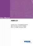
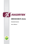
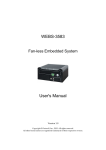
BX-800W
Fan-less Embedded System
User's Manual
Version 1.0a
Copyright, 2015. All rights reserved.
All other brand names are registered trademarks of their respective owners.
Preface
Table of Contents
How to Use This Manual
Chapter 1 System Overview....................................................................................................... 1-1
1.1 Introduction ....................................................................................................... 1-1
1.2 Check List........................................................................................................... 1-2
1.3 Product Specification........................................................................................ 1-2
1.4 Mechanical Dimension..................................................................................... 1-3
Chapter 2 System Installation.................................................................................................... 2-1
2.1 HDD Installation ............................................................................................... 2-1
2.2 CFEX Installation .............................................................................................. 2-2
2.3 Replacement of Additional Graphic Modules.............................................. 2-2
2.4 I/O Interfaces .................................................................................................... 2-4
2.4.1 Front View................................................................................................. 2-4
2.4.2 Rear View .................................................................................................. 2-5
2.5 Getting Started................................................................................................... 2-7
Chapter 3 BIOS Setup Information............................................................................................ 3-1
3.1 Entering Setup – Launch System Setup......................................................... 3-1
3.2 Main .................................................................................................................... 3-2
3.3 System Setup Utility ......................................................................................... 3-3
3.4 Configuration .................................................................................................... 3-3
3.5 Boot ................................................................................................................... 3-23
3.6 Security ............................................................................................................. 3-25
3.7 Exit..................................................................................................................... 3-26
Chapter 4 Important Instructions .............................................................................................. 4-1
4.1 Note on the Warranty....................................................................................... 4-1
4.2 Exclusion of Accident Liability Obligation ................................................... 4-1
4.3 Liability Limitations / Exemption from the Warranty Obligation............ 4-1
4.4 Declaration of Conformity............................................................................... 4-1
Preface
How to Use This Manual
The manual describes how to configure your BX-800W system to meet various
operating requirements. It is divided into four chapters, with each chapter
addressing a basic concept and operation of Fan-less Embedded System.
Chapter 1: System Overview. Present what you have in the box and give you an
overview of the product specifications and basic system architecture for this fan-less
embedded system.
Chapter 2: System Installation. Show the definitions and locations of all the
interfaces and describe a proper installation guide so that you can easily configure
your system.
Chapter 3: BIOS Setup Information. Specify the meaning of each setup parameters,
how to get advanced BIOS performance and update new BIOS. In addition, POST
checkpoint list will give users some guidelines of trouble-shooting.
Chapter 4: Important Instructions. Indicate some instructions which must be
carefully followed when the fan-less embedded system is used.
The content of this manual is subject to change without prior notice. These changes
will be incorporated in new editions of the document. The vendor may make
supplement or change in the products described in this document at any time.
System Overview
Chapter 1
System Overview
1.1
Introduction
We, announces BX-800W, a high performance and low power intelligent Box PC.
Powered by the 4th generation Intel® Core™ ULT (ultra low TDP) SoC (system on
chip) processor (formerly codenamed Haswell), this system is an ideal fan-less
controller for applications in digital signage, surveillance, image processing and
machine automation industries.
The BX-800W is powerful but not power hungry; it utilizes the dual-core 4th
generation Intel® Core™ processor with Intel® Turbo Boost Technology 2.0 (select
CPU SKUs), Intel® Hyper-Threading Technology and Enhanced Intel SpeedStep®
Technology. By adopting Intel’s SoC platform, which integrates CPU and PCH into a
BGA package, BX-800W is much smaller, sleeker and lighter compared to its previous
generation. In addition, the elimination of the 2-chip platform enables a more
effective thermal design for the BX-800W intelligent Box PC. Thanks to the highly
reliable chassis with a thermally-enhanced ripple fin design, BX-800W can operate
reliably in a temperature range from -20℃ to 55℃. Plus, combining anti-vibration
and shock resistance attributes, the fan-less and rugged BX-800W excels in harsh
environments.
BX-800W also offers clear and concise video and graphics capabilities because it
takes full advantage of the 4th generation Intel® Core™ processor with integrated
HD4400 graphics engine which outperforms its predecessor by over 20%. In addition
to the built-in triple-display interfaces, two additional display devices are made
available by our graphics modules; thus, it can support up to five display outputs by
extended mode in the OS. Product reliability and stability are definitely
uncompromised; BX-800W is rated IP40 and certified by industrial product quality
tests, such as an anti-vibration test of up to 5Grms and an anti-shock test of 50G. Our
BX-800W has proven itself to be a perfect solution for video/graphics-demanding
and automation control systems.
The versatile BX-800W system supports many other important features, including
up to 16GB of DDR3L memory, triple display with DVI-D, HDMI and Display Port,
5.1-CH audio and dual Intel® Gigabit Ethernet ports. It also offers rich compact I/O
functions including 2 x SATA, 2 x USB 3.0, 2 x USB 2.0, 1 x 8bits GPIO and 6x COM
ports. To enhance system flexibility, customers can further augment functions per
their specific needs via two antenna interfaces and an onboard SIM card holder for
WiFi or 3G/GPS module, and two mini PCIe sockets for expansion; one or more PCIe
expansion cassettes can be offered by counterparts of BX-800W for hungry demand.
A wide range of DC power input, 12V~24V, is accepted so that it can not only prevent
the system from damage due to power input change, but also expands the application
BX-800W User’s Manual
1-1
System Overview
fields of this Box PC to the automotive industry, for example. Last but not least, with
wall and panel mounting design, the BX-800W provides a slim and small footprint
Box PC weighing only 2 Kg that can fit anywhere easily, no matter if it’s in the office
or factory.
1.2
Check List
The BX-800W package should cover the following basic items:
One BX-800W Fan-less Embedded System
One 60W AC/DC Power Adapter DC-plug with screw
One Wall Mount Kit
Other Accessories
If any of these items is damaged or missing, please contact your vendor and keep all
packing materials for future replacement and maintenance.
1.3 Product Specification
System
System Chipset
CPU
BIOS
System Memory
Storage
Watchdog Timer
H/W Status Monitor
Expansion
External I/O
Series Ports
Display
USB
Audio
LAN
BX-800W User’s Manual
Intel® Haswell ULT SoC
Intel® Core™ i7-4650U,
1.7GHz, 4M L2 Cache, up to 3.3GHz, 15W TDP (2C/4T)
Intel® Core™ i5-4300U,
1.9GHz, 3M L2 Cache, up to 2.9GHz, 15W TDP (2C/4T)
Intel® Core™ i3-4010U,
1.7GHz, 3M L2 Cache, 15W TDP (2C/4T)
Intel® Celeron 2980U,
1.6GHz, 2M L2 Cache, 15W TDP (2C/2T)
AMI uEFI BIOS (SPI ROM)
Dual 204-pin SO-DIMM sockets support DDR3L 1333/1600
up to 16GB
1x 2.5” SATA HDD/SSD, 1x CFEX, 1x mSATA
Programmable via S/W from 1 sec. to 255 sec.
-Temperature (CPU & System)
-Voltage (CPU Vcore, VBAT, 5VSB, 12V, 5V, 3.3V)
-1x Full-size Mini-PCIe socket (USB+PCIe) + SIM holder
-1x Half-size Mini-PCIe socket (mSATA+PCIe)
2x COM Ports
(1x RS-232/422/485 selectable by BIOS & 1x RS-232)
1x DVI-D, 1x DP, 1x HDMI
2x Optional graphic modules (VGA/DVI-I/HDMI)
2x USB 3.0, 2x USB 2.0
Lin-out/MIC-in (ALC892)
2x Gigabit Ethernet (Intel® WGI218LM + WGI210AT)
1-2
System Overview
GPIO
Other
Power Supply Unit
Power Supply
Environment
Operating
Temperature
Storage Temperature
Relative Humidity
Operating Vibration
Operating Shock
Mechanical
Dimension (WxDxH)
Weight
Mounting
1x Programmable 8-bit digital I/O
-2x Antenna holes for WIFI or 3G/GPS module
DC 12~24V
-20℃ to 55℃
-40℃ to 80℃
95% @ 40℃, non-condensing
5Grms/5~500Hz, IEC 60068-2-64
50G, 11 msec, IEC 60068-2-27
253 x 160 x 60 mm; 9.2” x 6.2” x 4”
2 kg
Wall Mount
1.4 Mechanical Dimension
Front view of the BX-800W system
Rear view of the BX-800W system
BX-800W User’s Manual
1-3
System Overview
Top view of the BX-800W system
Side view of the BX-800W system
BX-800W User’s Manual
1-4
System Installation
Chapter 2
System Installation
This chapter provides you with instructions to set up your system. Definitions
and locations of all the interfaces are described so that you can easily configure
your system. For more detailed PIN assignment and jumper setting, please refer
to user’s manual of mother board.
2.1 HDD Installation
HDD cover locates at the back of the system.
Step 1. Turn the system upside down
Step 2. Unscrew the HDD cover
Step 3. Take out the HDD cover
Step 4. Install the HDD onto cover
Step 5. Plug the SATA and power cable Step 6. Screw the HDD cover back to
to connect the M/B and HDD
the system and finish installation
*Note: Glue it if needed
BX-800W User’s Manual
2-1
System Installation
2.2 CFEX Installation
CFEX is a new Compact Flash (CF) technology and adapting legacy CF type one
with advanced pin definitions. This helps overcome reliability issues with
standard commercial memory. CFEX also supports SATA 3.0, SPI and other
extensions, and achieves a read speed of 100 to 120Mbyte/s and write speed of 45
to 75Mbyte/s. Compared with other CF devices, it falls in the same low-cost
bracket as CF and CF SATA and is less expensive than CFAST.
Step 1. Unscrew the CFEX cover
Step 2. Take the CFEX card
Step 3. Insert the CFEX card into the Step 4. Finish installation
slot
2.3 Replacement of Additional Graphic Modules
In addition to the built-in triple-display interfaces, two additional display devices
are made available by our graphics modules; thus, the BX-800W system can
support up to five display outputs by extended mode in the OS.
*Note: Modules must be installed by our factory. It’s not recommended to buy
USB Graphic Module separately. But customers can replace the graphic module
with different interfaces by themselves.
Step 1. There are 3 kinds of graphic Step 2. Unscrew the trays of the
module that could be adopted: USB 3.0 graphic module which you want to
to VGA/DVI-I/HDMI
replace
BX-800W User’s Manual
2-2
System Installation
Step 3. Pull out the tray
Step 4. Unlock the cable from the tray
of graphic module
Step 5. Connect the cable to graphic Step 6. Install the tray of graphic
module with which you want to module back onto the system
replace and lock it
Step 7. Screw the tray of graphic Step 8. Finish installation
module properly
*Note: Drivers should be installed
properly to run the feature
BX-800W User’s Manual
2-3
System Installation
2.4
I/O Interfaces
2.4.1 Front View
ANT1 & ANT2 hole:
Antenna holes for WiFi or 3G/GPS module
GPIO:
GPIO PIN Definition
PIN No.
Signal Description
1
EC_GPI0
3
EC_GPI1
5
EC_GPI2
7
EC_GPI3
9
GND
11
N/A
13
N/A
15
N/A
PIN No.
2
4
6
8
10
12
14
X
Signal Description
GPO0 (Voltage from JP6)
GPO1 (Voltage from JP6)
GPO2 (Voltage from JP6)
GPO3 (Voltage from JP6)
VCC5
N/A
N/A
X
GPIO Output Voltage
JP6
Function
1-2 Short 5V
2-3 Short 3.3V ★ Default
BX-800W User’s Manual
2-4
System Installation
COM port:
RS-232
PIN No.
1
2
3
4
5
6
7
8
9
Signal Description
DCD#
RXD#
TXD#
DTR#
GND
DSR#
RTS#
CTS#
RI#
RS-232/422/485
*Note: RS-232/422/485 configuration is determined by BIOS setting.
Check BIOS setting for details.
PIN No.
Signal Description
1
DCD#/DT2
RXD#/DT+
3
TXD#/422R+
4
DTR#/422R5
GND
6
DSR#
7
RTS#
8
CTS#
9
RI#
2.4.2 Rear View
DC in: (Wide range DC source support, 12~24V)
Using the provided DC source to connect to the system
Power Button:
Press the power button to turn ON/OFF the system
BX-800W User’s Manual
2-5
System Installation
USB3.0 & USB 2.0:
Support four USB (Universal Serial Bus) ports, two USB 3.0 and two USB 2.0.
LAN:
Two Gigabit Ethernet (10/100/1000 Mbits/sec) LAN ports by using Intel
WGI218LM & WGI210AT GbE Ethernet Controller
HDMI:
Type A HDMI display output
DP:
DP (DisplayPort) display output
DVI-D:
DVI-D display output
Audio:
Connectors for MIC-In and Line-Out
CFEX:
CFEX is a new Compact Flash (CF) technology and adapting legacy CF type one
with advanced pin definitions. This helps overcome reliability issues with
standard commercial memory. CFEX also supports SATA 3.0, SPI and other
extensions, and achieves a read speed of 100 to 120Mbyte/s and write speed of 45
to 75Mbyte/s. Compared with other CF devices, it falls in the same low-cost
bracket as CF and CF SATA and is less expensive than CFAST.
Optional Graphic Module:
There are 3 kinds of graphic module that could be adopted.
*Note: Modules must be installed by our factory. It’s not recommended to buy
USB Graphic Module separately.
USB 3.0 to VGA
USB 3.0 to DVI-I
USB 3.0 to HDMI
BX-800W User’s Manual
2-6
System Installation
2.5 Getting Started
It is easy to get the system started.
Step 1. Make sure the power supply Step 2. Press the power button to turn
(12~24V) is connected properly
on the system
*Note: Power LED shines BLUE when
system is “ON”; ORANGE when “OFF”
BX-800W User’s Manual
2-7
BIOS Setup Information
Chapter 3
BIOS Setup Information
Mother board for BX-800W uses AMI BIOS structure stored in Flash ROM. These
BIOS has a built-in Setup program that allows users to modify the basic system
configuration easily. This type of information is stored in CMOS RAM so that it is
retained during power-off periods. When system is turned on, mother board
communicates with peripheral devices on the carrier board and checks its
hardware resources against the configuration information stored in the CMOS
memory. If any error is detected, or the CMOS parameters need to be initially
defined, the diagnostic program will prompt the user to enter the SETUP
program. Some errors are significant enough to abort the start up.
3.1 Entering Setup – Launch System Setup
Power on the computer and the system will start POST (Power On Self Test)
process. When the message below appears on the screen, press <DEL> key will
enter BIOS setup screen.
Press <DEL> to enter SETUP
If the message disappears before responding and still wish to enter Setup, please
restart the system by turning it OFF and On or pressing the RESET button. It can
be also restarted by pressing <Ctrl>, <Alt>, and <Delete> keys on keyboard
simultaneously.
BX-800W User’s Manual
3-1
BIOS Setup Information
3.2 Main
Use this menu for basic system configurations, such as time, date etc.
Build Time, Processor Brand Name, Processor Speed, Install Memory, etc
These items show the firmware and memory specifications of your system.
Build Time
The BIOS Release Date.
Processor Brand Name / Processor Speed
This value will change depend of different CPUs. And please make sure the
Processor that you’ll install will be compatible with mother board’s User’s
Manual
System Date
The date format is <Day>, <Month> <Date> <Year>. Use [+] or [-] to configure
system Date.
System Time
The time format is <Hour> <Minute> <Second>. Use [+] or [-] to configure
system Time.
BX-800W User’s Manual
3-2
BIOS Setup Information
Access Level
3.3 System Setup Utility
To enter the system setup utility, press <F1> on either the main keyboard or
Console Redirection host computer’s keyboard during POST.
Table 1 lists the available menus in the system setup utility. Each menu is
equivalent to a functional group and consists of all correlated BIOS settings.
Menu
Main
Configuration
Boot
Security
Save & Exit
Table 1. System Setup Utility menus
Usage
Display a summary of the system and configure the
system date and time.
Configure the system interfaces, system
management, power management, thermal
management, and other system characteristics.
Configure boot device priority settings.
Configure user authentication requirements.
Save changes and exit the system setup utility, or
restore default settings.
3.4 Configuration
Use this menu to set up the items of special enhanced features.
BX-800W User’s Manual
3-3
BIOS Setup Information
BX-800W User’s Manual
3-4
BIOS Setup Information
CPU Configuration
It is not necessary to make any change just take the default value.
Here you’ll see the Max Processor Speed/Processor Cores/Intel HT technology
then you can adjust if you want to “disabled” the Hyper-threading.
BIOS Item
Usage
Item-Specific Help
Hyper-threading
-Disabled
-Enabled ★ Default
Active Processor Cores
-All ★ Default
-1
Intel
Technology
-Disabled
-Enabled ★ Default
Enabled for Windows XP /
Linux and Disabled for other OS
Select the number of physical
cores to enable in each processor
package
When enabled, a VMM can
utilize the additional hardware
capabilities provided by
Vanderpool Technology
Enabled/Disabled Intel
SpeedStep
Virtualization
EIST
Turbo Mode
CPU C states
Enhanced C1 state
CPU C3 report
CPU C6 report
BX-800W User’s Manual
-Disabled
-Enabled ★ Default
-Disabled
-Enabled ★ Default
-Disabled
-Enabled ★ Default
-Disabled
-Enabled ★ Default
-Disabled
-Enabled ★ Default
-Disabled
-Enabled ★ Default
Turbo Mode
CPU C states
Enhanced C1 state
CPU C3 report
CPU C6 report
3-5
BIOS Setup Information
Chipset Configuration
It is not necessary to make any change just take the default value.
BIOS Item
High Precision Timer
Azalia
VT-d
Port 80h Redirection
BX-800W User’s Manual
Usage
-Disabled
-Enabled★ Default
-Disabled
-Enabled★ Default
-Disabled ★ Default
-Enabled
-LPC Bus
-PCIE Bus
Item-Specific Help
Enabled/Disabled VT-d
function on MCH
3-6
BIOS Setup Information
AMT Configuration
BIOS Item
Intel AMT
Un-Configure ME
Disable ME
BX-800W User’s Manual
Usage
-Disabled
-Enabled ★ Default
-Disabled ★ Default
-Enabled
-Disabled ★ Default
-Enabled
Item-Specific Help
Disables/Enabled iAMT
function
3-7
BIOS Setup Information
Memory Configuration
BX-800W User’s Manual
3-8
BIOS Setup Information
LAN Configuration
BIOS Item
Launch PXE
Policy
Usage
OpROM -Disabled ★ Default
-Enabled
-Disabled
Intel LAN I218 Controller
-Enabled ★ Default
-Disabled ★ Default
Wake on LAN
-Enabled
-Disabled
Intel LAN I210 Controller
-Enabled ★ Default
-Disabled ★ Default
Wake on LAN
-Enabled
BX-800W User’s Manual
Item-Specific Help
Enable/Disable Intel
LAN I218
Enable/Disable Intel
LAN I210
3-9
BIOS Setup Information
Graphic Configuration
BIOS Item
Primary Display
Internal Graphics
Aperture Size
DVMT Pre-Allocated
BX-800W User’s Manual
Usage
-Auto
-IGFX ★ Default
-PCIE
-Auto
-Disabled
-Enabled ★ Default
-128MB
-256MB ★ Default
-512MB
-32M
-64M
-96M
-128M
-160M
-192M
-224M
-256M ★ Default
-288M
Item-Specific Help
Select which of IGFX/PCI
Graphics should be
Primary Display or select
Secondary Display for
switchable Graphics
Keep IGD Enabled based
on the setup options
Select the Aperture Size
Select DVMT 5.0
Pre-Allocated (Fixed)
Graphics Memory size
used by the internal
Graphics Device
3-10
BIOS Setup Information
-320M
-352M
-384M
-416M
-448M
-480M
-512M
-1024M
DVMT Total Gfx Mem
Primary IGFX Boot
Display
Secondary IGFX Boot
Display
DVI Display Type
BX-800W User’s Manual
-128MB
-256MB ★ Default
-MAX
Select DVMT5.0 Total
Graphics Memory size
used by the Internal
Graphics Device
-VBIOS Default
-HDMI
-DVI ★ Default
-DP
-VBIOS Default
-HDMI ★ Default
-DVI
-DP
-1024x768 ★ Default
-1280x1024
-1360x768
-1920x1200
3-11
BIOS Setup Information
PCI/PCIE Configuration
It is not necessary to make any change just take the default value.
BIOS Item
PCI Latency Timer
Maximum Payload
Maximum Read Request
BX-800W User’s Manual
Usage
-32 PCI Bus Clocks
-64 PCI Bus Clocks
-96 PCI Bus Clocks
-128 PCI Bus Clocks
-160 PCI Bus Clocks
-192 PCI Bus Clocks
-224 PCI Bus Clocks
-248 PCI Bus Clocks
-Auto
-128 Bytes
-256 Bytes
-512 Bytes
-1024 Bytes
-2048 Bytes
-4096 Bytes
-Auto
-128 Bytes
-256 Bytes
-512 Bytes
-1024 Bytes
Item-Specific Help
3-12
BIOS Setup Information
-2048 Bytes
-4096 Bytes
PCH PCI Express Configuration
It is not necessary to make any change just take the default value.
BX-800W User’s Manual
3-13
BIOS Setup Information
PCI Express Root Port 1/2/4/6 (Only take Port 1 as an example)
It is not necessary to make any change just take the default value.
BIOS Item
Usage
PCI Express Root Port -Disabled
-Enabled ★ Default
1/2/4/6
-Disabled ★ Default
-L0S
ASPM
-L1
-L0S L1
-Auto
-Auto ★ Default
PCIe Speed
-Gen1
-Gen2
BX-800W User’s Manual
Item-Specific Help
Control PCI Express root
port
Control PCIe Active State
Power Management
setting
Select PCIe Speed to Gen1
or Gen2
3-14
BIOS Setup Information
SATA Configuration
Determines how SATA controller (s) operate.
BIOS Item
SATA Controller(s)
SATA Mode Selection
SATA Controller Speed
Port 0~3
Hot Plug
External SATA
SATA Device Type
BX-800W User’s Manual
Usage
-Enabled ★ Default
-Disabled
-Disabled
-IDE
-AHCI ★ Default
-RAID
-Default
-Gen1
-Gen2
-Gen3 ★ Default
-Disabled
-Enabled ★ Default
-Disabled ★ Default
-Enabled
-Disabled ★ Default
-Enabled
-Hard Disk Drive
-Solid State Drive ★
Default
Item-Specific Help
Determines how SATA
controller (s) operate
Determines how SATA
controller (s) operate
3-15
BIOS Setup Information
-Disabled ★ Default
-Enabled
SATA DEVSLEP Idle -Disabled ★ Default
Timeout Configuration
-Enabled
Device Sleep
USB Configuration
Configure USB controller and other advanced setting.
BIOS Item
Usage
Legacy USB support
-Enabled ★ Default
-Disabled
XHCI Mode
XHCI Hand-off
BX-800W User’s Manual
Item-Specific Help
Enables Legacy USB
support. AUTO option
disables legacy support if no
USB devices are connected.
DISABLE option will keep
USB devices available only
for EFI applications.
-Smart Auto ★ Default
-Auto
-Enabled
-Disabled
Manual
-Enabled ★ Default
-Disabled
3-16
BIOS Setup Information
-Enabled
-Disabled★ Default
USB
Mass
Storage -Enabled ★ Default
Driver Support
-Disabled
PCH USB Configuration
-Disabled ★ Default
-USB Ports per-Port 0~7
-Enabled
Disable
EHCI Hand-off
Control each of the USB
ports disabling
PCH USB Configuration
USB Ports per-Port 0~7
BX-800W User’s Manual
3-17
BIOS Setup Information
Power Control Configuration
It is not necessary to make any change just take the default value.
BIOS Item
Enable Hibernation
Usage
-Disabled
-Enabled ★ Default
ACPI Sleep State
-S3 Only
(Suspend to RAM)
Power loss function
-Always Off ★ Default
- Always On
-Last State
Wake system with Fixed -Disabled ★ Default
Time
-Enabled
Wake on Ring
BX-800W User’s Manual
-Disabled ★ Default
-Enabled
Item-Specific Help
Enable or Disable
Hibernate Funtion
Select the highest ACPI
sleep state when the
SUSPEND button is
pressed
Select AC Power state
when power is re-applied
after a power failure
Enable or disable System
wake on alarm event.
When enabled, System
will
wake
on
the
hr:min:sec specified
N/A
3-18
BIOS Setup Information
TPM Configuration
BIOS Item
Security Device Support
Usage
-Disabled ★ Default
-Enabled
Item-Specific Help
Enabled/Disabled TPM
Function
Super IO Configuration
Enable/Disable Watch Dog Timer
BX-800W User’s Manual
3-19
BIOS Setup Information
Serial Port 0~6 Configuration
BIOS Item
WDT Controller
Timer Unit
Timer value
Serial Port 1~6
RS-232/422/485 Control
Option
BX-800W User’s Manual
Usage
-Disable ★ Default
-Enabled
- Second ★ Default
- Minute
20 ★ Default
-Disable
-Enable ★ Default
-RS-232
-RS-422
-RS-485
Item-Specific Help
Setting Serial Port 1~6
3-20
BIOS Setup Information
Hardware Monitor
Provide on board sensor reading information.
BIOS Item
CPU Smart Fan Control
Smart Fan Start
Temperature
Smart Fan Full Speed
Temperature
BX-800W User’s Manual
Usage
-Disable ★ Default
-Enable
-50 ★ Default
Item-Specific Help
Disable / Enable Smart
Fan function
-50 ★ Default
3-21
BIOS Setup Information
Serial Port Console Configuration
Configure console redirection on serial port.
BIOS Item
Usage
Serial Port 1 Console
Redirection
-Disabled ★ Default
-Enabled
Console Redirection
-Disabled ★ Default
-Enabled
BX-800W User’s Manual
Item-Specific Help
Control Console
Redirection
enable/disable
3-22
BIOS Setup Information
3.5 Boot
Boot Priority Order: Please adjust the order depend of your needs.
Boot NumLock State
Selects Power-on state for NumLock.
Choices: OFF, ON.
GateA20 Active
UPON REQUEST – GA20 can be disabled using BIOS service.
ALWAYS – do not allow disabling GA20; this option is useful when any RT code
is executed above 1MB.
Choices: Upon Request, Always.
Option ROM Messages
Set Display mode for Option ROM.
This item is used to determine the display mode when an optional ROM is
initialized during POST. When set to [Force BIOS], the display mode used by AMI
BIOS is used. Select [Keep Current] if you want to use the display mode of
optional ROM.
Choices: Force BIOS, Keep Current.
BX-800W User’s Manual
3-23
BIOS Setup Information
Interrupt 19 Capture
Interrupt 19 is the software interrupt that handles the boot disk function.
When “Enabled”, this BIOS feature allows the ROM BIOS of these host
adaptors to "capture" Interrupt 19 during the boot process so that drives
attached to these adaptors can function as bootable disks. In addition, it allows
you to gain access to the host adaptor's ROM setup utility, if one is available.
When “Disabled”, the ROM BIOS of these host adaptors will not be able to
"capture" Interrupt 19. Therefore, you will not be able to boot operating systems
from any bootable disks attached to these host adaptors. Nor will you be able to
gain access to their ROM setup utilities.
Choices: Disabled, Enabled.
Launch Storage OpROM
Choices: Disabled, Enabled.
Full Screen Logo
Choices: Disabled, Enabled.
Post Report
Choices: Disabled, Enabled.
Summary Screen
Choices: Disabled, Enabled.
Fast Boot
Choices: Disabled link, Enabled.
Boot mode Select
Choices: LEGACY, UEFI.
Boot Option #1 ~#7
Sets the system boot order.
Choices: Built-in EFI Shell, other bootable devices, Disabled.
BX-800W User’s Manual
3-24
BIOS Setup Information
3.6 Security
Set or clear the Supervisor account’s password.
Administrator Password
Set Setup Administrator Password
User Password
Set User password
BX-800W User’s Manual
3-25
BIOS Setup Information
3.7 Exit
Equal to F10, save all changes of all menu, then exit setup configure driver.
Finally resets the system automatically.
Save Changes and Exit
Exit system setup after saving the changes
Discard Changes and Reset
Reset the system without saving the changes.
Restore Defaults
Restore/Load Default Values for all the setup options.
BX-800W User’s Manual
3-26
Important Instructions
Chapter 4
Important Instructions
This chapter includes instructions which must be carefully followed when the
fan-less embedded system is used.
4.1 Note on the Warranty
Due to their limited service life, parts which, by their nature, are especially subject to
wear are not included in the guarantee beyond the legal stipulations.
4.2 Exclusion of Accident Liability Obligation
We shall be exempt from the statutory accident liability obligation if users fail to
abide by the safety instructions.
4.3 Liability Limitations / Exemption from the Warranty Obligation
In the event of damage to the system unit caused by failure to abide by the hints in
this manual and on the unit (especially the safety instructions), we shall not be
required to respect the warranty even during the warranty period and shall be free
from the statutory accident liability obligation.
4.4 Declaration of Conformity
EMC
CE/FCC Class A
This equipment complies with Part 15 of the FCC Rules. Operation is subject to the
following two conditions:
1. This equipment may not cause harmful interference.
2. This equipment must accept any interference that may cause undesired operation.
Applicable Standards:
EN 55022: 2006 + A1: 2007, Class A
EN 61000-3-2: 2006
EN 61000-3-3: 1995 + A1: 2001 + A2: 2005
EN 55024: 1998 + A1: 2001 + A2: 2003
IEC 61000-4-2: 2008
IEC 61000-4-3: 2006 + A1: 2007
IEC 61000-4-4: 2004
IEC 61000-4-5: 2005
IEC 61000-4-6: 2007
IEC 61000-4-8: 1993 + A1: 2000
IEC 61000-4-11: 2004
FCC 47 CFR Part 15 Subpart
BX-800W User’s Manual
4-1