1
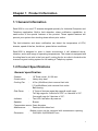
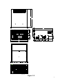
RACK-3030 CTI CHASSIS
USER’S MANUAL
Ver 2.0
Copyright Notice
This document and product is copyrighted, September 2000, by ICP Electronics Inc.
All rights are reserved. No part of this manual may be reproduced, copied, or
translated without prior notice to ICP Electronics Inc.
The information provided in this document is for reference only. We do not assume
any responsibility arising out of the application of the products. This manual is
subject to change without any notice.
Rack-3030, IEI are trademark of ICP Electronics Inc.
1
Table of Contents
Chapter 1
Product Information
1.1 General Information
1.2 Product Specifications
1.3 Mechanical Dimension
Chapter 2
Installation Procedure
2.1 Removing the chassis cover
2.2 Disk Drives Installation
2.3 The Filter
2.4 Backplanes Installation
2.5 Power Supply Installation
Chapter 3
Removable Fan
3.1 Introduction
3.2 The Fan signal and connection
Chapter 4
Fault Resilient Function
4.1 Introduction
4.2 Fault Detection and Alarm Notification
4.3 Visible Alarm and Audible Alarm
Chapter 5
Power Supply
5.1 Single Power ACE-935A
5.2 Redundant Power ARH-6400F (For ATX)
5.3 Redundant Power ARH-4400F (For AT)
2
Chapter 1 Product Information
1.1 General Information
Rack-3030 is our new CTI chassis designed specially for Industrial Computer and
Telephony application. Built-in fault detection, alarm notification capabilities, to
name some of the special features of the product. These special features will
prevent your system from shutting down without prior notice.
The fault detection and alarm notification can detect the temperature of CPU,
chassis, speed of the fan, fan failure, power failure conditions .
Rack-3030 is designed to work in harsh environment, it will withstand shock,
vibration, and a wide range of operating temperatures. The chassis is equipped with
4 cooling fans for air inlet in the front and 2 cooling fan for air outlet in the both side
to ensure a good cooling system for full loading in Telephony system.
1.2 Product Specifications
General specification
- Chassis
- Construction
- Cooling Fan
:
:
:
19” Rack mount , 6 U 20-slot.
Heavy-duty steel.
4 Fan (92x92mm) front remove & air inlet.
2 Fan(60x60mm) side remove & air outlet.
Ball bearing.
- Disk Driver
:
2 Types of devices cages(big cages & small cage).
Two big cages for 2 devices of 5.25” or 4 devices of 3.5”.
One small cage for 3 devices of 3.5”.
- Indicator
:
Two LED- fan failure & power on.
- Speaker
:
Buzzer.
- Temperature sensor: Case & system.
- Maintenance
:
Desktop with rubber foot.
Bottom cover can be removed with maintenance opening.
- Dimension
:
W431(481.8)xD520xH267 mm
3
Backplanes
We provide variant of backplanes to be applied with the Rack-3030 depends or your
demands: BP-20S, BP-20SD, BP-20ST, BP-20SQ, PCI-18SD, PCI-19S, PX-19S,
PX-20S, PX-20S2.
Power Supply
The Rack-3030 comes with our ACE-935A– the Single Power Supply or with the
Horizontal type Redundant Power Supply of ARH-6400F(for ATX) or ARH-4400F(for
AT). See Chapter 5 for the detail description of the power supply.
Working Environment
- Operating Temperature
- Relative Humidity
- Vibration
:
:
:
- Shock
:
0~50°C
5~95% Relative
5-17 Hz, 0.1” double amplitude displacement
17-500 Hz, 1.5G acceleration peak to peak
10G acceleration peak to peak
4
1.3 Mechanical Dimension
519.7
516.7
Figure 1.1 and figure 1.2 below show the dimension of the Rack-3030
TOP VIEW
519.7
57.2
88.9
88.9
RESET
266.6
88.9
40.0
431.0
3.0
464.6
128.0
92.1
92.1
92.1
518.5
481.8
FRONT VIEW
RIGHT SIDE VIEW
BOTTOM VIEW
230
REAR VIEW
Figure 1.1
5
516.7
519.7
TOP VIEW
519.7
57.2
88.9
88.9
RESET
266.6
88.9
40.0
431.0
3.0
464.6
128.0
92.1
92.1
92.1
518.5
481.8
FRONT VIEW
RIGHT SIDE VIEW
BOTTOM VIEW
115
115
REAR VIEW
Figure 1.2
6
Chapter 2 Installation Procedure
To install the Rack-3030, please read this chapter carefully and prepare all the cards
that you would like to install in the chassis to save time.
The control panel functions of Rack-3030 include Rocker Switch for Power ON/OFF,
System Reset (3 reset for options) , Buzzer ON/OFF, and Two LED indicators: Fan
failure for one of four fan, Power On to monitor the system’s status.
To set up the system, please follow the steps below:
2.1 Removing the chassis cover
The cover is mounted by 2 captive screws at the front of the chassis, remove
them by push the sink pool and slide the cover to the rear of the chassis. See
figure 2.1.
Figure 2.1
7
2.2 Disk Drives installation
The disk drivers are fastened inside device cages which will allow you to
install and re-install the drive without removing the cover of the chassis.
1. Remove the 2 captive screws on the front of device cage.
2. Remove the device cage by slide it towards the front of the chassis.
Please refer to figure 2.2 & 2.3 for the disk drives installation.
Figure 2.2
Figure 2.3
8
2.3 The Filter
The filter of the Rack-3030 is located at the upper side of the front panel. The
filter should be removed and cleaned at least once a month to achieve optimum
performance. The filter can be removed by remove 6 screws from Fan Modules.
Take out the old filter, replace it with the new one if it’s already worn out. Then
fasten 6 screws to put it back. (Figure 2.4)
Filt
er
Filt
er
Figure 2.4
9
2.4 The Backplanes installation
There are variant of backplanes to be applied with the Rack-3030 depends or
your demands: BP-20S, BP-20SD, BP-20ST, BP-20SQ, PCI-18SD, PCI-19S,
PX-19S, PX-20S, PX-20S2.
Figure 2.5 &2.6 below illustrates how to install the backplanes on the Rack3030.
Figure 2.5
Figure 2.6
10
2.5 Power Supply Installation
If the Rack-3030 is installed with the Horizontal type Redundant Power Supply
and you may simply install it by plug the Power unit into the case as shown in
the figure 2.7 below.
Figure 2.7
11
Chapter 3 Removable Fan
3.1 Introduction
The removable fan module is one of the unique features of Rack-3030 where
you may remove and install the fan from the front of the chassis without
opening the chassis cover. This will give you more convenient and flexibility to
replace the fan if necessary.(Fig 2.4 & 3.1)
3.2 The Fan signal and Connection
Figure 3.2 below showed the fan signal and how to connect it to the cable of
the control panel.
Figure 3.1
12
To
Po
we
rS
up
ply
PO
WE
R
CO
RD
W
BL HITE
UE
BL
BR ACK
OW
N
Figure 3.2
13
Chapter 4 Fault Resilient Function
4.1 Introduction
The fault resilient of Rack-3030 is a fault detection and alarm notification
system. When any fail function occurs, the unit will alert the users.
RACK-3030 control panel is built up from ALARMBOARD A60 MODULE.
Fan sensor: FAN1、FAN2、FAN3 and FAN4
The RED LED indicator located at the front door will light if one fan failed.
Buzzer on/off button x 1: control buzzer on / off.
When the system buzzer is alarming, push the button will stop the buzzer.
Reset button x 4: (option)
Four reset buttons are available to control individual multi system installation.
4.2 Fault Detection and Alarm Notification
The Rack-3030 the system fault conditions that will be detected are:
Fan Failure: If any of the cooling fan fails.
Power Failure: If any of the power fails.
4.3 Visible Alarm
However, the alarm indicator (LED) will stay blinking until the fault condition is
solved.
The fault condition include Fan Failure, Power Failure, the system.
14
A60
JP1
JP4
JP3
JP6
JP5
JP8
To Power Supply
Connector(4p)
M
20C
70
CM
60C
M
M
30C
M
22C
M
2
2C
M
22C M
22C
M
20C
M
20C
M
30C
M
0C
10
M
30C
M
30C
To Power
Cord
ED
NL D
R O LE
WE FAIL
O
P AN
F
To System
CM
80
Reset Button
FOR CLEAR SYSTEM
15
Chapter 5 Power Supply
5.1 Single Power ACE-935A
5.1.1 INPUT SPECIFICATIONS
l
l
l
Input Voltage
The range of input voltage is from 85V AC to140VAC or 170VAC to
270VAC selected by slide switch install in rear panel of the metal box.
Input frequency
The range of input voltage is from 47 HZ to 63 HZ
Inrush current
The inrush current will not exceed 15A at 115V AC input or 30A at 230V
AC input cold start,25℃.
5.1.2 OUTPUT SPECIFICATIONS
l The load range
Output#
1
2
3
4
Output
+5V
+12V
-12V
-5V
min.load
3.0A
0.1A
0A
0A
rated load peak load
40A
10A
8A
0.7A
0.3A
Voltage accuracy
5.00V to 5.10V
11.28V to 12.72V
-11.40V to –12.60V
-4.75V to –5.25V
At factory, all outputs in 50﹪rated load condition, the +5V output is set to
between 4.90V and 5.10V.The other outputs are checked to be within the
specified voltage accuracy range.
l Output power
The total DC continuous power shall be kept within (300W).Peak load on
each output can’t be allowed for more then 5 sec. When the input voltage
less then 90VAC,total DC continuous power should not exceed 250W.
l Ripple and noise
The peak to peak ripple and noise for each output is less than 1﹪of each
output voltage at rated load,115/230VAC.Measureing is done by 15MHz
band width limited oscilloscope and terminated each output with a 47 uF
capacitor.
l Line regulation
The output line regulation is less than + -1﹪ over the line range
specified in paragraph 2.1
16
l Load regulation
The output voltage load regulation is less than the values in the following
table by changing each output load + -40﹪ form 60﹪ rated load, and
keep all other outputs at 60﹪ rated load.
Output#
1
+ -3﹪
2
+ -5﹪
3
+ -2﹪
4
+ -2﹪
l Hold up time
Hold up time is loger than 20ms at 115V/230V input by measuring from the
last AC line charging pulse to the point than +5V drop down to +4.75V.
l Power good signal
When power is turned on, the power good signal will go high 100ms to
500ms after all output DC voltages are within regulation limits.
l Power fail signal
The power fail signal will go low at least 0.5ms before any of the output
voltages fall below regulation limits.
5.1.3 OUTPUT PROTECTIVE FEATURES
For some reason the power supply fails to control itself, the build-in over
voltage protection circuit will shut down the outputs to prevent damaging
external circuits. The trip point of crowbar circuit is around 5.9V to 7.0V.The
power supply will go into hiccup mode against short circuit or over load
conditions, and will auto-recovery white faulty conditions are removed.
5.1.4 EFFICIENCYS
The efficiency is higher than 68﹪ by measuring at nominal line, and rated
load.
5.1.5 ENVIRONMENT SPECIFICATIONS
l Operating temperature
0℃ to 40℃
Use Input 104V, 244V Testing temperature.
l Storage temperature
-40℃ to +70℃
17
5.1.6 INTERNATIONAL STANDARDS
l Safety standards
Designed to meet the following standards:
UL 1950 D3
VDE EN 60 950
l EMI standards
Designed to meet the following conducted & radiation Limitd:
FCC docket 20780 curve “B”
5.2 Redundant Power ARH-6400F (For ATX)
5.2.1 Scope
This specification defines the performance characteristics of a grounded,
single-phase,400 watts,6 output level power supply. This specification also
defines world wide safety requirements and manufactures process test
requirements.
5.2.2 Input requirements
l Voltage (sinusoidal)
Low range
90∼132 VAC
normal
100∼125 VAC
High range
normal
180∼260 VAC
200∼240 VAC
A manual switch shall be provided to select the appropriate range.
l Frequency
The input frequency range will be 47hz∼63hz.
l Steady-state current
10.0A/5.0A amps max
(Excluding AC output current) at any low/high range input voltage.
l Inrush current
50/100 amps @110/220 VAC (at 25 degrees ambient cold start for one
power supply)
5.2.3 Output requirements
l DC load requirements
Normal
Load current
Output voltage
Max.
Min
+5V
20~36A 7.0A
+12V
17.0A
2.5A
-5V
0.8A
0.0A
-12V
0.8A
0.0A
+3.3V
25.0A
3.0A
+5Vsb
1A
0.1A
+5V and +3.3V total output max:180W
Regulation tolerance
Max.
Min.
+5%
-5%
+7%
-7%
+10%
-10%
+10%
-10%
+5%
-5%
+5%
-5%
18
Remark:
When operationg with single module
1) If +5V is at high load and the other channels are at low load , the requlation
tolerance of +12V will be +10%。
2) If +12V is at low load and the other channels are at high load , the requlation
tolerance of +12V will be +10%。
l Regulation and protection
Output DC
Line
Load
Cross
voltage
regulation
regulation
regulaion
+5V
±50mV
±400mV
±350mV
-5V
±50mV
±800mV
±400mV
+12V
±50mV
±750mV
±650mV
-12V
±50mV
±800mV
±800mV
+3.3V
±50mV
±200mV
±150mV
+5Vsb
±50mV
±200mV
±150mV
l Ripple and noise
Specification
+5V
60mV (P-P)
+12V
120mV (P-P)
-5V
120mV (P-P)
-12V
150mV (P-P)
+3.3V
60mV (P-P)
+5Vsb
50mV (P-P)
l Ripple voltage test circuit
-5V
+5V
+3.3V
+
0.1
+
220
220
-12V
+
0.1
-
220
0.1
-
+12V
0.1
220
+
+
220
0.1
-
0.1uf is ceramic the other is tantalum.
19
l
l
l
Overshoot
Any overshoot at turn on or turn off shall be less 15% of the nominal
voltage value ,all output shall be within the regulation limit of section
3.2 before issuing the power good signal of section 6.0.
Efficiency
Power supply efficiency typical 65% at 115V,full load.
Power factor can not below 0.6
Remote on/off control
The power supply DC outputs (with the exception of +5Vsb) shall be
enabled with an active-low, TTL-compatible signal(“ps-on”)
When ps-on is pulled to TTL low,the DC outputs are to be enabled.
When ps-on is pulled to TTL high or open circuited,the DC outputs are
to be disabled.
The DC output enable circuit shall be selv compliant.
5.2.4 Protection
l
l
Input (primary)
The input power line must have an over power protection device in
accordance with safety requirement of section 9.0
Output (secondary)
Over power protection
The power supply shall provide over power protection on the power
supply latches all DC output into a shutdown state. Over power of this
type shall cause no damage to power supply,after over load is
removed and a power on/off cycle is initiated,the power supply will
restart.
Trip point total power min. 110%,max. 150%(one unit power supply)
Over voltage protection
If an over voltage fault occurs (internal of the power supply),the power
supply will latch all DC output into a shutdown state before when +5V
output exceeds 130% of its nominal value.
Short circuit
A short circuit placed on any DC output to DC return shall cause no
damage and power supply latch.
20
5.2.5 Power supply sequencing
l
l
l
Power on (see fig.1)
Hold up time
When power shutdown DC output 5V must be maintain 16msec in
regulation limit at nominal input voltage.
Power off sequence (see fig. 1)
5.2.6 Signal requirements
l
l
Power good signal (see fig. 1)
The power supply shall provide a "power good" signal to reset system
logic,indicate proper operation of the power supply,and give advance
warning of impending loss of regulation at turn off. This signal shall be
a TTL compatible up level (2.4V to 5.25V) when +5V output voltage
are present and above the minimum UV sense levels specified in
paragraph 6.2 ,or a down level (0.0V to 0.8V) when any output is
below its minimum UV sense level.
At power on, the power good signal shall have a turn on delay of at
least 100ms but not greater than 500ms after the output voltages
have reached their respective minimum sense levels.
Under voltage (UV) sense levels
Output
Minimum sense voltage
+5V
+4.50V
5.2.7 Environment
l
l
l
l
Operation
Temperature
0 to 50 degrees centigrade
Insulation resistance
Primary to secondary
: 30 meg. Ohm min. 500 VDC
Primary to FG
: 30 meg. Ohm min. 500VDC
Dielectric withstanding voltage
Primary to secondary
: 1500 VAC for 1 sec.
Primary to FG
: 1500 VAC for 1 sec.
Leakage current
3.5 mA. max. at nominal voltage 250 VAC
5.2.8 Safety
l
l
Underwriters laboratory (UL) recognition.
The power supply designed to meet UL 1950.
Canadian standards association (CUL) approval
The power supply designed to meet CSA 1402C & CSA 950.
21
l TUV approval
The power supply shall be designed to meet TUV EN-60950.
5.2.9 Reliability
l Burn in
All products shipped to customer must be burn in. The burn in shall be
performed at high line voltage.
5.2.10 Mechanical requirements
l Physical dimension :190 mm * 334 mm * 95 mm
l Connector power input (DELTA 10GEEG3E) or equivalent.
5.2.11 Warning method
l Audio alarm(buzzer sund ,resttl).
l Faulted.
l Power defective signal delivery(TTL ,low active).
POWER ON
POWER OFF
AC IN
Vn +5V OUTPUT
Vm
Vm +4.5V
OV
Vb
Va +3.3V OUTPUT
OV
OV
Tm
LOWER LEVER 0.5V MAX
Tson Trs
POWER GOOD SIGNAL
Tdon
HIGH LEVEL 4.5V~5.25V
Tovs Tdoff
Vn
Nominal voltages +5V
Vm
Minimum voltages +4.5V
Va
Nominal voltages +3.3V
Vb
+2.0V max
Tson
Switch on time (500 ms. max.)
Trs
+5V rise time (100ms. max.)
Tdon
Delay turn-on (100ms. < Tdon < 500ms.)
Tdoff
Delay turn-off (1 ms. min.)
Toff
Hold up time (16ms. min.)
Tm
Delay time of +3.3V (1ms. min)
Figure 1
22
5.3 Redundant Power ARH-4400F (For AT)
5.3.1 Scope
This specification defines the performance characteristics of a grounded,
single-phase,400 watts,6 output level power supply. This specification also
defines world wide safety requirements and manufactures process test
requirements.
5.3.2 Input requirements
l Voltage (sinusoidal)
Low range
90∼132 VAC
normal
100∼125 VAC
High range
180∼260 VAC
normal
200∼240 VAC
A manual switch shall be provided to select the appropriate range.
l Frequency
The input frequency range will be 47hz∼63hz.
l Steady-state current
10.0A/5.0A amps max
(Excluding AC output current) at any low/high range input voltage.
l Inrush current
50/100 amps @110/220 VAC (at 25 degrees ambient cold start for one
power supply)
5.3.3 Output requirements
l DC load requirements
Normal
Output voltage
+5V
+12V
-5V
-12V
Load current
Max.
Min
20~36A 7.0A
17.0A
2.5A
0.8A
0.0A
0.8A
0.0A
Regulation tolerance
Max.
Min.
+5%
-5%
+7%
-7%
+10%
-10%
+10%
-10%
+5V and +3.3V total output max:180W
Remark:
When operationg with single module
1) If +5V is at high load and the other channels are at low load , the requlation
tolerance of +12V will be +10%。
2) If +12V is at low load and the other channels are at high load , the requlation
tolerance of +12V will be +10%。
23
l Regulation and protection
Output DC
Line
voltage
regulation
+5V
±50mV
-5V
±50mV
+12V
±50mV
-12V
±50mV
l Ripple and noise
Load
regulation
±400mV
±800mV
±750mV
±800mV
Cross
regulaion
±350mV
±400mV
±650mV
±800mV
Specification
+5V
60mV (P-P)
+12V
120mV (P-P)
-5V
120mV (P-P)
-12V
150mV (P-P)
l Ripple voltage test circuit
-5V
+5V
+
0.1
+
220
220
-12V
0.1
+12V
+
0.1
220
+
220
0.1
-
0.1uf is ceramic the other is tantalum.
l Overshoot
Any overshoot at turn on or turn off shall be less 15% of the nominal
voltage value ,all output shall be within the regulation limit of section 3.2
before issuing the power good signal of section 6.0.
l Efficiency
Power supply efficiency typical 65% at 115V,full load. Power
factor can not below 0.6
l Remote on/off control
The power supply DC outputs (with the exception of +5Vsb) shall be
enabled with an active-low, TTL-compatible signal(“ps-on”)
When ps-on is pulled to TTL low,the DC outputs are to be enabled.
When ps-on is pulled to TTL high or open circuited,the DC outputs are to be
disabled.
The DC output enable circuit shall be selv compliant.
24
5.3.4 Protection
l
l
Input (primary)
The input power line must have an over power protection device in
accordance with safety requirement of section 9.0
Output (secondary)
Over power protection
The power supply shall provide over power protection on the power
supply latches all DC output into a shutdown state. Over power of this
type shall cause no damage to power supply,after over load is
removed and a power on/off cycle is initiated,the power supply will
restart.
Trip point total power min. 110%,max. 150%(one unit power supply)
Over voltage protection
If an over voltage fault occurs (internal of the power supply),the power
supply will latch all DC output into a shutdown state before when +5V
output exceeds 130% of its nominal value.
Short circuit
A short circuit placed on any DC output to DC return shall cause no
damage and power supply latch.
5.3.5 Power supply sequencing
l
l
l
Power on (see fig.1)
Hold up time
When power shutdown DC output 5V must be maintain 16msec in
regulation limit at nominal input voltage.
Power off sequence (see fig. 1)
5.3.6 Signal requirements
l
Power good signal (see fig. 1)
The power supply shall provide a "power good" signal to reset system
logic,indicate proper operation of the power supply,and give advance
warning of impending loss of regulation at turn off. This signal shall be
a TTL compatible up level (2.4V to 5.25V) when +5V output voltage
are present and above the minimum UV sense levels specified in
paragraph 6.2 ,or a down level (0.0V to 0.8V) when any output is
below its minimum UV sense level.
At power on, the power good signal shall have a turn on delay of at
25
least 100ms but not greater than 500ms after the output voltages
have reached their respective minimum sense levels.
l
Under voltage (UV) sense levels
Output
Minimum sense voltage
+5V
+4.50V
5.3.7 Environment
l
l
l
l
Operation
Temperature
0 to 50 degrees centigrade
Insulation resistance
Primary to secondary
: 30 meg. Ohm min. 500 VDC
Primary to FG
: 30 meg. Ohm min. 500VDC
Dielectric withstanding voltage
Primary to secondary
: 1500 VAC for 1 sec.
Primary to FG
: 1500 VAC for 1 sec.
Leakage current
3.5 mA. max. at nominal voltage 250 VAC
5.3.8 Safety
l Underwriters laboratory (UL) recognition.
The power supply designed to meet UL 1950.
l Canadian standards association (CUL) approval
The power supply designed to meet CSA 1402C & CSA 950.
l TUV approval
The power supply shall be designed to meet TUV EN-60950.
5.3.9 Reliability
l Burn in
All products shipped to customer must be burn in. The burn in shall be
performed at high line voltage.
5.3.10 Mechanical requirements
l Physical dimension :190 mm * 334 mm * 95 mm
l Connector power input (DELTA 10GEEG3E) or equivalent.
26
5.3.11 Warning method
l Audio alarm(buzzer sound ,resettle).
l Faulted.
POWER ON
POWER OFF
AC IN
Vn +5V OUTPUT
Vm
Vm +4.5V
OV
POWER GOOD SIGNAL
OV
HIGH LEVEL 4.5V~5.25V
LOWER LEVER 0.5V MAX
Tson Trs
Tovs Tdoff
Tdon
Vn
Nominal voltages +5V
Vm
Minimum voltages +4.5V
Tson
Switch on time (500 ms. max.)
Trs
+5V rise time (100ms. max.)
Tdon
Delay turn-on (100ms. < Tdon < 500ms.)
Tdoff
Delay turn-off (1 ms. min.)
Toff
Hold up time (16ms. min.)
Figure 1
27