1
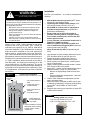
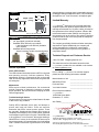
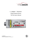
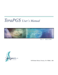
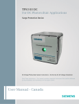
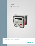
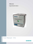
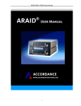
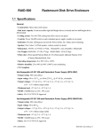
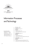
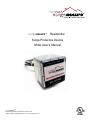
surgeassureTM Residential
Surge Protective Device
S50A User’s Manual
surgeassureTM
14550 58th Street North Clearwater, Florida 33760
1.800.727.0669 - [email protected] - www.surgeassure.com
Introduction
Specifications
Thank you for choosing the surgeassureTM S50A Residential
Surge Protective Device.
Temperature Operating
-40oC (-40oF) to 60oC (+140oF)
Temperature Storage
-55oC (-67oF) to 65oC (+149oF)
Save this manual! It includes instructions for obtaining
warranty service and for returning a defective device.
Please read and understand all information in this manual
prior to installation. The procedures contained herein
are not intended to supersede local or national electrical
codes. Check all applicable electrical codes to ensure
compliance. In all instances, local and national electrical
code requirements are to be followed.
This manual provides instructions for installing the S50A
Surge Protective Device (SPD). The S50A SPD (Figure
1) can be mounted three ways. The preferred way is to
mount the SPD directly to the outside of the electrical
panel equipment using the pipe nipple on the body of the
SPD. Other options include standard 35mm DIN-rail (not
included) or via the attached L-bracket for standard flat
mounting surface. Some of these methods require the
use of additional conduit and hardware (not provided).
See Figure 4 for further information on mounting methods.
The S50A provides protection from damaging transient
voltage surges and spikes. Proper installation is imperative
to maximize the effectiveness and overall performance of
this device. This device must be installed by a licensed
electrician. The electrician should follow the steps outlined
in this manual to insure proper installation.
Note: surgeassureTM products are extensively tested to
industry standards as set by ANSI/IEEE C62.41.1-2002,
C62.41.2-2002, and C62.45-2002. The S50A is listed to the
most recent edition of UL 1449 Third Edition (Sept 2009).
During installation into an electrical system, the S50A must
NOT be energized until the electrical system is installed,
inspected and tested. All conductors must be connected
and functional, including neutral (if required).
Failure to follow the guidelines in this manual can lead to
abnormally high voltage being applied to the SPD. This
may cause the S50A unit to become inoperative. The
warranty does not cover an incorrectly installed device.
Do not high potential test the electrical system with the SPD
connected. Failure to disconnect the SPD during elevated
voltage testing will result in damage to the suppression
components and/or other electronic components (see
Safety Information).
Wire Size & Installation Torque 10 AWG; 18 inch-pounds
Appropriate Circuit Breaker
based on conductor size
30A (SPD includes internal OCP)
NEMA 250 Enclosure Rating
Type 4X with appropriate
sealing & sealing conduits
Parts List and Inspection
Items included in the package consist of the following:
• 1 - S50A Surge Protective Device including 3’ (~1m)
conductors
• 1 - ¾” conduit nut
• 1 - Data Sheet
• 1 - User’s Manual (this document)
Carefully inspect each item in the package for signs of
damage. If damage is found, please contact surgeassureTM
Technical Support: 1-800-727-0669. For more information
about this product or other surgeassureTM products, visit
www.surgeassure.com.
Safety Information
This section provides pertinent safety information that must
be considered before installing the SPD.
• Do not install this device during a lightning storm.
• This device is rated NEMA 4X. Suitable for indoor
and outdoor applications. The customer must seal
the conduit nipple against the panel using watertight
fittings (not supplied) to ensure a watertight
connection.
• Do not install the surge protector in an excessively
hot or moist location.
• Other safety considerations are listed on the
following page.
! CAUTION
BONDING BETWEEN CONDUIT CONNECTIONS IS
NOT AUTOMATIC AND MUST BE PROVIDED AS PART
OF THE INSTALLATION.
CONDUCTING DIELECTRIC AND/OR HIGH POTENTIAL
TESTING WILL CAUSE INTERNAL DAMAGE TO THE
SPD UNIT. DO NOT PERFORM DIELECTRIC OR HIGH
POTENTIAL TESTS WITH THE PHASE OR NEUTRAL
SPD WIRES CONNECTED
Page 2
!
WARNING
VERIFY ALL POWER CIRCUITS ARE DE-ENERGIZED
BEFORE MAKING CONNECTIONS
The voltage rating of the device and system must always be
verified before energizing the SPD. All electrical connections
should be performed by a qualified (licensed) electrician. All
wiring must comply with the National Electrical Code (NEC)
and applicable local codes.
• Maintenance of this Surge Protective Device should
be performed by qualified electrical personnel only.
• During normal operation, hazardous voltages are present inside the unit.
• When servicing this unit, be sure to follow all electrical
safety precautions.
• All power sources to this unit should be locked off
before servicing. This will prevent the risk of receiving
an electrical shock.
S50A is a Type 1 SPD. S50A is suitable for use almost
anywhere (not as a plug-in SPD). Type 1 SPDs are
evaluated more rigorously by UL 1449 for 2008 NEC®
Article 285 compliance. Type 1 SPDs and their connecting
leads have been evaluated for line side applications
without need for supplemental overcurrent protection.
Type 1 SPDs include internal overcurrent protection. As a
generalization, there are practical maintenance reasons for
installing on the load side of the main overcurrent device
(i.e. Type 2 installation). When connected on load side of
main disconnect, we recommend connecting via a 30A
circuit breaker due to 10 AWG conductors. The circuit
breaker serves as a disconnect switch and provides NEC®
imposed short circuit protection to the conductors in Type
2 or 4 applications. (cUL units are Type 2 due to different
cUL criteria.)
Typical Panel Installation
Figure 1
(Type 1 or individual equipment installations may vary)
To Protected
Loads
A
• Use closest breaker to
SPD
• Locate SPD close to
intended breaker
B
• Keep Leads Short as
Possible
• Avoid Sharp Bends
BREAKER
N
Installation
Pre-Plan your installation. You need to accomplish the
following:
•
•
•
•
•
•
•
Meet all National and Local codes (NEC® Article
285 and UL 1449 address SPDs)
Confirm System voltage to SPD voltage (120V
SPD will fail instantly on 240V, 277V, etc.)
Mount SPD as close to panel or equipment as
possible to keep leads short (long leads hurt
performance substantially)
Ensure leads are as short and straight as
possible, including neutral. If using a breaker,
use a breaker position that is close to the SPD
and the panel’s neutral
If using a breaker, recommended breaker size is
30A due to 10 AWG conductor
Make sure system is grounded per NEC® and
clear of faults before energizing SPD (inadvertent
system problem may fail SPD).
Never Hi-Pot test Any SPD (will prematurely fail
SPD)
1. Use voltmeter to check voltages and ensure correct
SPD. See Data Sheet for specs & wire-outs
2. Determine Mounting method (See Figure 2) –
weather resistant equipment may be required
3. Remove power from panel/source. Confirm panel/
source is deenergized.
4. Identify breaker location and SPD location. Position
SPD such that LED is best visible.
5. Mount SPD – weather resistant applications require
additional sealing, o-rings, etc. (not included)
-- Remove an appropriately sized knockout from
panel.
-- Connect conductors as appropriate – short and
straight as possible
6. Label or mark conductors as appropriate (neutral:
white, energized: black)
7. Make sure system is bonded per NEC® and is clear
of hazards or faults before energizing (N-G bonding
not per NEC® will fail SPDs: #1 cause of SPD
failures)
8. Energize and confirm proper operation of green LED
indicator and/or options.
Figure 2
G
• Rotate S50A such
that LED indicator is
most visible
Sealing gasket: two choices
1.) At 3/4" nom. thread: ID is 1.05"
2.) At 0.14" high 'base step': ID is 1.25"
• Outdoor installation requires
appropriate weather sealing
at nipple (gasket, sealing
conduit, etc.)
Page 3
Dimensions and Weight
Figure 3
4.13”
Weight: 1.60 lbs
(0.73 kg)
3.26”
3.31”
3.26”
Limited Warranty
3.57”
3/4”-14
1.15”
Sized for std 35mm DIN-rail
Figure 4
•
•
•
shows problems on startup, there is reasonable chance of
bonding/grounding/misapplication issue. This permanently
damages the unit. If not corrected, it will happen again.
S50A Mounting Options
3/4” pipe nipple (conduit nut included)
Standard 35mm DIN-rail (not included)
L-bracket tightens onto DIN-rail (available upon request)
Standard flat mounting surface
Attach L-bracket to surface via mounting holes
surgeassureTM warrants it’s AC electrical distribution
equipment protection products against defective workmanship and materials for 10 years. Liability is limited to
the replacement of the defective product. A Return Material Authorization number (RMA #) must be given by
the company prior to the return of any product. Returned
products must be sent to the factory with the transportation charges prepaid.
The company specifically disclaims all other warranties,
expressed or implied. Additionally, the company will
not be responsible for incidental or consequential
damages resulting from any defect in any product or
component thereof.
Technical Support and Customer Service
1.800.727.0669 · [email protected]
Std. 3/4”-14 Nipple
DIN-rail Mount
(rail not incl.)
Bracket Mount
for flat surfaces
Normal Operation
Green LED Indicator
The LED indicator illuminates when the SPD is energized
and operating correctly. Indicator operation: Every
suppression element is connected via logic to the green
LED. Should any suppression element fail, the green LED
will extinguish.
Maintenance
SPDs require minimal maintenance. We recommend
periodic inspection of diagnostic indicators to ensure
proper operation. We also recommend keeping the SPD
clean as appropriate.
Troubleshooting & Service
Please contact us for any service related issues. We want
to take care of any problems.
Quality SPDs withstand severe duty and attempt to
protect their load until failure. There are electrical
anomalies that SPDs cannot protect against. These
are generally Sustained Overvoltages also known as
Temporary Overvoltages (TOVs). In this context, Sustained
Overvoltages may be only a few cycles. Failed SPDs tend
to be symptoms, not root causes. We suggest treating a
failed SPD as a ‘canary in the coalmine’ as there may be
larger issues at play. As a generalization, the single largest
‘killer’ of SPDs is reference to ground issues. If the SPD
Page 4
This manual as well as information about the entire
surgeassureTM product line are available on the Internet
at: www.surgeassure.com.
Prior to calling surgeassureTM for technical support,
please have the following information available:
Model Number of unit: _________________________
Manufacture Date:
_________________________
Purchase Date:
_________________________
Your Order Number:
_________________________
Return Shipment Address:
surgeassureTM
14550 58th Street North
Clearwater, FL 33760
Attn: RMA#______________________
surgeassureTM
14550 58th Street North Clearwater, Florida 33760
1.800.727.0669 - [email protected] - www.surgeassure.com
A Division of Advanced Protection Technologies, Inc.
APT’s Quality Management System is ISO 9001:2000 Certified
rB06.11.12.rs #8221