1
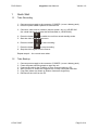
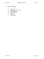
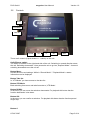
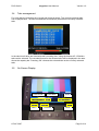
megacine
Mobile Field Recording System
USER
MANUAL
Preliminary Version 1.0
Copyright DVC GmbH 2007
DVC GmbH
1
Quick Start
1.1
Take Recording
megacine User Manual
Version 1.0
1. Connect power supply to the connector „POWER“ (or use a battery pack).
2. Press the power switch upwards to start the unit.
3. Connect a video source (camera, playout system, etc.) to „HD-SDI IN1“
(for a dual link signal connect the second cable to „HD-SDI IN2“).
to switch the unit into record standby mode.
4. Press the button
5. Start the video signal at the source.
6. Press the button
to start recording.
7. Press the button
to stop recording.
8. Stop the video signal from the source.
Repeat steps 4 – 8 to record more takes.
1.2
Take Backup
1.
2.
3.
4.
5.
6.
Connect power supply to the connector „POWER“ (or use a battery pack).
Press the power switch upwards to start the unit.
Connect the unit via the FireWire or Fibre Channel cable to a PC.
Wait until the PC shows the megacine as a newly connected hard disk.
Copy files (takes are shown as folders, frames as single files).
Disconnect the unit from the PC.
© DVC 2007
Page 2 of 14
DVC GmbH
2
megacine User Manual
Version 1.0
Scope of Supply
1x
1x
1x
1x
1x
1x
1x
1x
© DVC 2007
megacine unit
Power Supply 15V DC (6.5 ft.)
Power Cord (6 ft.)
FireWire Cable (6 ft.)
BNC Cable (5.5 ft.)
Software CD
User Manual
Transport Case
Page 3 of 14
DVC GmbH
megacine User Manual
3
Functional Description
3.1
Modes of Operation
Version 1.0
The diagram above shows the main modes of operation.
You can change between those modes by operating the controls or by connecting /
disconnecting the HD-SDI inputs or FireWire / Fibre Channel outputs.
© DVC 2007
Page 4 of 14
DVC GmbH
3.2
megacine User Manual
Version 1.0
Controls
Menu
VTR Mode
Take list
DOWN
OK
C
UP
REC
There are 9 controls (8 push-buttons + 1 switch) on the unit:
On/Off Power switch:
The switch is located on the right hand side of the unit. Switching in upward direction starts
the unit. Switching downwards 1 time causes the unit to go into „Suspend Mode”. A second
switching downwards turns the unit off.
Button Menu:
Access the menu and settings. While in “Record Mode” / “Playback Mode“ a status
information can be displayed.
Button Take list:
In “VTR Mode” you have access to the take list.
Button VTR Mode:
Back switching from menu and take list mode to „VTR Mode“.
Button DOWN:
In the menu you can move the selection downwards. For playback this button has the
function backwards / slow down.
Button OK:
In the menu you can confirm a selection. For playback this button has the function pause /
single step.
Button C:
© DVC 2007
Page 5 of 14
DVC GmbH
megacine User Manual
Version 1.0
In the menu you can cancel an action. Playback will be stopped.
Button UP:
In the menu you can move the selection upwards. For playback this button has the function
forward / speed up. In record standby mode this button starts the recording.
Button REC:
This button switches the system into record standby mode. An input signal has to be
connected. The recording process can than be started by the button UP.
© DVC 2007
Page 6 of 14
DVC GmbH
3.3
megacine User Manual
Version 1.0
Menu structure
Setting can be changed over the on-screen menu. User input occurs over the buttons UP /
DOWN, OK and C (cancel). The default values for Input and Output are given in brackets.
3.3.1
Input Settings
Input Settings – Interlace Mode:
The Interlace Mode can not be recognized from the video signal, so you need to do it
manually. You can choose between Progressive segmented Frame („PsF“) and interlaced
(„i“). This setting only affects the marking of a take, there is no functional impact to the
operation of the unit. (Default „PsF“)
Input Settings - Dual Link Format:
The format transmitted over Dual Link can not be clearly distinguished. Therefore you need
to set the input format for Dual Link manually. (Default „RGB 4:4:4“)
Input Settings – Vari Frame:
Time code can be embedded in the metadata. Therein certain frames can be marked valid /
invalid for recording. If this option is set „On“, only valid frames will be recorded. (Default
„Off“)
Input Settings – Timecode:
Here you can choose the Timecode that should be used for recording. If set to „LTC extern“
the externally connected LTC input over LTC IN will be used. If set to „LTC embedded“ the
embedded LTC in the video signal over HD-SDI is used. If the option is set to „Intern“ the unit
will generate a Timecode itself starting at each take with 00:00:00:00. Since the LTC frame
counter is only specified up to 30 frames/s, with High-Speed formats having frame rates
higher then 30 frames/s one LTC value will be used two frames (see also SMPTE 12M).
(Default „Intern“)
3.3.2
Output Settings
Output Settings – Frame rate:
The frame rate of the output can be selected here. If set to „Original“ the takes will be played
back as recorded. If a selected frame rate is not supported a message will be displayed and
the take will be played back as recorded. (Default „Original“)
Output Settings – Left Audio Channel:
Currently not supported. (Here the left audio channel for analog stereo output can be
selected from one of 16 embedded audio channels.)
Output Settings – Right Audio Channel:
Currently not supported. (Here the right audio channel for analog stereo output can be
selected from one of 16 embedded audio channels.)
© DVC 2007
Page 7 of 14
DVC GmbH
megacine User Manual
Version 1.0
Output Settings – Genlock:
If this option is set at „On“ and a Genlock signal is applied, in the “Playback Mode” the HDSDI output will be synchronized with the Genlock signal. The Genlock signal has to feature
the same frame rate as the HD-SDI output. An automatic detection of the Genlock frame rate
does not occur. (Default „Off“)
3.3.3
System Configuration
System Configuration – Status:
Here you get status information about the system. Included e.g. are system time, complete
and available capacity as well as temperature.
System Configuration – Test Pattern:
Several video formats for testing can be displayed by the unit.
System Configuration – RAID:
Currently not supported. (Information about the status of the RAID and the hard disks can be
displayed and reset)
System Configuration – Service Mode:
Via the serial RS232 interface additional setting can be made. The Service Mode is
recommended for Service personnel only and is not needed for normal operation.
System Configuration – Standard Settings:
All settings of the unit will be reset to their default values. Previously recorded takes remain
untouched.
3.3.4
Delete Takes
Delete Takes – Delete Last Take:
The last recorded take will be deleted. It is not possible to delete a take located between
other takes.
Delete Takes – Delete All:
All recorded takes will be deleted.
© DVC 2007
Page 8 of 14
DVC GmbH
3.4
megacine User Manual
Version 1.0
Take management
For each take the recording time, length and format is stored. The currently selected take
can be played back. The last recorded take automatically becomes the currently selected
take.
In the take list all takes are listed with their recording time. Using the buttons UP / DOWN a
take can be selected. The recorded format for the selected take will be displayed in the area
above the capacity bar. Pressing „OK“ chooses the selected take as the currently selected
take.
3.5
On-Screen Display
Color Format
Take #
© DVC 2007
Frame Rate
Timecode
SL/DL
Mode
Page 9 of 14
DVC GmbH
megacine User Manual
Version 1.0
The on-screen display shows the current frame, in „Playback Mode“ as well as in „Record
Mode”. Additionally information about format, frame rate and time code are displayed. The
settings of the unit are also submitted over the on-screen menu.
3.6
Connectors Video/Audio/Timecode
3.6.1
Overview
Tally OUT
DVI OUT
Record IN
LTC OUT
LTC IN
Genlock IN
HD-SDI IN1
HD-SDI IN2
HD-SDI
OUT1
HD-SDI
OUT2
© DVC 2007
Page 10 of 14
DVC GmbH
3.6.2
megacine User Manual
Version 1.0
Description
HD-SDI IN1 / IN2
(2x BNC)
IN1 for Single Link formats,
IN1 + IN2 for Dual Link formats
HD-SDI OUT1 / OUT2
(2x BNC)
Single Link formats identical on OUT1 and OUT2,
Dual Link formats on OUT1 + OUT2
LTC IN / OUT
(2x BNC)
Timecode Input / Output for Recording / Playback
Genlock IN
(1x BNC)
Tri-Level and Bi-Level analogue Sync for Playback
Tally OUT
(1x TRS 3.5)
Tally Light Control for Recording
Record IN
(1x TRS 3.5)
Remote Control for Recording
DVI OUT
(1x DVI-I)
Single Link / Dual Link video output
(currently not supported)
© DVC 2007
Page 11 of 14
DVC GmbH
megacine User Manual
3.7
Connectors PC/Remote/Power
3.7.1
Overview
Version 1.0
FireWire
Power Switch
Fibre Channel
RS232/422
Analog Audio
Power
© DVC 2007
Page 12 of 14
DVC GmbH
3.7.2
megacine User Manual
Version 1.0
Description
FireWire
(1x FW-6)
IEEE 1394a for Frame Output to PC Systems
Fibre Channel
(1x LC)
FC-SW for Frame Output to PC Systems
Analogue Audio
(1x TRS 3.5)
Audio Monitoring Output for Recording / Playback
Power Switch
Up / Down switch for Turn ON / Suspend / Turn OFF
RS232/422
(1x DE-9)
RS232 for Service Mode /
RS422 for Remote VTR Controlling (Odetics, Sony 9-pin)
Power
(1x XLR4)
12-36 V DC for Power Supply /
Battery Pack over optional Adapter Cable
© DVC 2007
Page 13 of 14
DVC GmbH
megacine User Manual
4
Technical Specification
4.1
Power supply
Input voltage
Version 1.0
12 - 36 volts DC
Typical total input power
Operation:
Idle:
Suspend:
4.2
approx. 90-120 W
approx. 50 W
approx. 35 W
Environmental Temperature
Temperature range
in operation:
Temperature range for
stocking:
40 – 105 °F
5 – 140 °F
The temperature range in operation is mainly defined by the hard disks. As an alternative for
consumer hard disks, automotive hard disks can be applied.
4.3
Mechanical Features
IP protection class
Dimensions
Weight
4.4
IP 2X
7.8’’ x 8.3’’ x 11.4’’
18.5 lbs
Vibrations
Vibrations during operation reduce the performance of the system. Depending on intensity
and duration, recording / playback errors or permanent breakdown may occur.
www.digitalvideo.de
© DVC 2007
Digital Video Competence GmbH
Landsberger Strasse 23-25
82110 Germering
Germany
Fon: +49 - 89 - 894446 400
E-Mail: [email protected]
Page 14 of 14