1
Microcontroller Programming
LMP2: Metrowerks’ CodeWarrior IDE
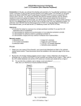
Laboratory LMP2 – Example based introduction Metrowerks’ CodeWarrior IDE
Objectives
-
To learn how to generate a small Metrowerks CodeWarrior project
To debug an application using the simulator of CodeWarrior
To debug an application using CodeWarrior’s source-level debugger Hi-Wave
Introduction
The Motorola MC9S12DP256B/C (e-www.motorola.com) is a member of Motorola’s
HC12 series of 16-bit microcontrollers. With its large number of peripheral units (5
independent CAN interfaces) this controller is widely used for industrial automation,
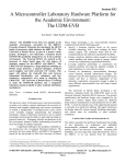
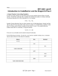
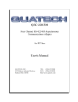
automotive applications and consumer electronics. Figure LMP2-1 gives an overview
of all hardware units of the Motorola MC9S12DP256B/C microcontroller.
Figure LMP2-1
The MC9S12DP256B/C microcontroller
In addition to a substantial number of general purpose digital I/O lines, the controller
features 8 pulse width modulation (PWM) channels, two 8-channel A/D converters (101
Microcontroller Programming
LMP2: Metrowerks’ CodeWarrior IDE
bit), 2 asynchronous serial communication interfaces (SCI), 3 synchronous serial
peripheral interfaces (SPI), an Inter-IC (IIC, I2C) bus interface, 5 CAN bus interfaces,
an Enhanced Capture Timer (ECT), 256 kByte Flash EEPROM, 4 kByte EEPROM, 12
kByte RAM, etc. The bus speed can go up to 50 MHz, with operations being clocked at
up to 50 MHz.
Figure LMP2-2 presents a more detailed overview of the internal structure of the
MC9S12DP256B/C.
Figure LMP2-2
Internal structure of the MC9S12DP256B/C
2
Microcontroller Programming
LMP2: Metrowerks’ CodeWarrior IDE
Notice that some pins are used for multiple purposes. For example, the general
purpose digital I/O port PAD shares its pins with the A/D converter. This is to say that
there are two (or more) internal circuits connected to these pins. The sample-and-hold
amplifier of the A/D converter unit is connected in parallel to the output driver(s) of port
PAD (configured as output) as well as the corresponding input buffer amplifiers (PAD
configured as input). This practice of sharing the limited number of pins between
several hardware units is common to most microcontrollers. It has to be taken into
account when considering the suitability of a particular controller for a specific task.
A number of programming environments are available for the MC9S12DP256B/C, both
commercial as well as free software (GNU, www.gnu-m68hc11.org). In this exercise
we will use Metrowerks’ CodeWarrior, an Integrated Development Environment (IDE)
which includes many useful features to assist us with the software development
process. A 12 kByte code-size limited evaluation version can be obtained free of
charge from www.metrowerks.com/MW/download/default.asp.
Creating a new project using a project stationery template
In this section we are going to experiment with a small project which simply outputs a
bit pattern on the LEDs connected to one of the digital I/O ports of the microcontroller.
To keep things simple, we are going to develop our programs based on a predefined
project template (stationery).
CodeWarrior assists software designers by providing them with templates for projects
(stationery) which define the most commonly used settings and compiler options. For
this set of laboratory exercises the stationery Dragon12_small has been created. This
template defines an empty project with three targets: Simulation, Monitor and Release.
A target can be seen as a recipe of how to compile a number of source files for a
particular target platform/environment. A project which is targeted at a simulator might
be different from a project which runs on a development board such as the Dragon-12
and the final release version usually differs from the corresponding debug version. For
example, the release version may be programmed into a secure area of Flash
EEPROM to prevent unauthorised and/or accidental modifications of the code.
The stationery Dragon12_flat has been put together for laboratory exercises using the
Wytec Dragon-12 development board. It is configured to build applications with a flat
memory model. This implies a linear 16-bit address space ranging from 0 to 0xFFFF.
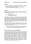
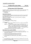
Figure LMP2-3 shows the memory map of this memory model.
The free evaluation version of the CodeWarrior compiler can produce executable files
with a maximum code size of up 12 kByte. All our programs will therefore be compiled
for the Flash EEPROM section from 0x4000 to 0x7FFF. Variables can be allocated
(statically or dynamically) within the 12 kByte of on-chip RAM (0x1000 to 0x3FFF). The
4 kByte EEPROM (0x0000 to 0x0FFF) will not be used.
3
Microcontroller Programming
0x0000
0x1000
LMP2: Metrowerks’ CodeWarrior IDE
EEPROM (4 kByte)
Registers (1 kByte)
RAM (12 kByte)
← Program variables will be
allocated here
0x4000
FLASH ROM_4000 (16 kByte)
← Program code will be stored
here
0x8000
FLASH BANK WINDOW
(16 kByte)
(not used in the flat memory model)
0xC000
FLASH ROM_C000 (16 kByte)
0xF800
HCS12 Serial Monitor (2 kByte)
Interrupt vector table (0xFF80-...)
0xFFFF
Figure LMP2-3
Memory map of the flat memory model
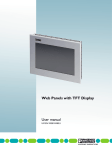
Notice that the special function registers (Figure LMP2-4) are mapped into an area
overlapping with the EEPROM. The lowest 1024 bytes of the 4k EEPROM will be
masked by these registers and cannot be used – unless “special steps” are being
taken (the starting address of the EEPROM can be redefined). Also notice that a small
monitor program resides in the upper 2k of the available memory space. This program
will allow us to communicate with the target through the serial communication interface
SCI0 during the debugging phase. The monitor program is in a secure area of the chip;
it can therefore not be erased by accident.
4
Microcontroller Programming
Figure LMP2-4
LMP2: Metrowerks’ CodeWarrior IDE
First 1024 bytes of the memory map: Special function registers
Launch the CodeWarrior IDE from the Windows Start menu (entry: Programs →
Metrowerks CodeWarrior → CW 12 V3.0 → CodeWarrior). You should be presented
with an empty screen.
From the File menu select ‘New…’ to create a new HCS12 Stationery project. Enter a
project name (e.g. myHello) and click on ‘Set… (Location)’. This allows you to save
your project in a folder of your choice (Figure LMP2-5).
5
Microcontroller Programming
Figure LMP2-5
LMP2: Metrowerks’ CodeWarrior IDE
Creating a new project using an HCS12 Stationery
A small requester appears allowing you to choose the type of stationery to be used
(Figure LMP2-6). Expand the list of supported boards and select Dragon12_flat.
Figure LMP2-6
Selecting the Dragon12_flat stationery
CodeWarrior now makes a copy of the Dragon12_flat stationery project and saves it as
myHello. If everything worked so far, you should be presented with a fully functional
6
Microcontroller Programming
LMP2: Metrowerks’ CodeWarrior IDE
project with a small main program (Figure LMP2-7, all project groups have been
expanded).
Figure LMP2-7
The CodeWarrior project stationery Dragon12_flat
The left-hand side of Figure LMP2-7 shows the (fully expanded) project tree for target
Simulator. There are a number of target groups (symbolised by a small folder icon)
containing a variety of files, e.g. source files, header files, configuration files and
special command files. Start12.c is a module which runs before your main program;
most hardware dependent initialisations are carried out by a function called _Startup
(defined in Start12.c). Group prm includes parameter files such as burner.bbl
(describes the making of Flash programmable S-Record files) and the memory map
definition file _MC9S12DP256_FLAT.prm. The library group includes statically linked
libraries as well as special function register definition files. Finally, the debugger groups
configure the built-in simulator and debugger (Hi-Wave).
Fortunately, you can ignore most of these groups and files – they have been included
to make your life easier. The only target group you will have to deal with is Sources.
This group contains the main program file main.c, a pre-defined interrupt vector table
isr_vectors.c and two support files pll.c and pll.h.
Inspect the target column (red bulls-eye with black arrow, cf. Figure LMP2-7). This
column specifies if a project file belongs to the chosen target (currently: Simulator).
Observe that the debugger configuration file Simulator.ini is part of this target, whereas
the file Monitor.ini is not. Similarly, the debugger command files sermon_[name].cmd
are not part of target Simulation (no dot in the target column).
Change the target from Simulator to Monitor. This can be done by selecting Monitor
from the pull-down menu in the target browser toolbar (Figure LMP2-8).
7
Microcontroller Programming
LMP2: Metrowerks’ CodeWarrior IDE
Figure LMP2-8
Changing targets
Notice that the Monitor target includes a different subset of files, e.g. the monitor
command files sermon_[name].cmd instead of sim_[name].cmd. Change the target to
Release. The release target produces a Motorola S-Record file which can be
downloaded (‘burnt’) to the microcontroller’s Flash EEPROM. Release includes the
‘burner’ configuration file burner.bbl. This is a format specification of the downloadable
S-Record file.
Switch back to the Simulator target and open the source file main.c.
/* Example program for the Wytec Dragon 12 (MC9S12DP256C) */
#include <mc9s12dp256.h>
#include "pll.h"
/* derivative information */
/* defines _BUSCLOCK, sets bus frequency to _BUSCLOCK MHz */
void main(void) {
/* set system clock frequency to _BUSCLOCK MHz (24 or 4) */
PLL_Init();
/* set port B as output (LEDs) */
DDRB = 0xff;
// Port B is output
PORTB = 0x55;
// switch on every other LED
/* forever */
for(;;){}
}
This small program first boosts the system bus clock from half the value of the crystal
oscillator (0.5 x 4 MHz = 2 MHz) to the maximum clock frequency of 24 MHz
(PLL_Init). It then defines the pins of port B as outputs (DDRB = 0xFF – setting a bit in
the Data Direction Register of port B activates the corresponding output driver circuit).
8
Microcontroller Programming
LMP2: Metrowerks’ CodeWarrior IDE
On the Dragon12 development board, port B is connected to an array of LEDs. The 3rd
line of main finally sets every other bit of port B to ‘1’ (0x55 = 0101.0101). This displays
an on/off pattern on the LEDs.
To simulate this program within the CodeWarrior debugger/simulator (Hi-Wave) click
on the small green ‘Debug’ button (Figure LMP2-9).
Figure LMP2-9
Launching the debugger/simulator (Hi-Wave)
CodeWarrior works out the dependencies of the current target (Simulator) and, if
required, rebuilds the code. A small red check symbol in the leftmost column of the
target browser window marks files that have been modified and need to be re-compiled
(see Figure LMP2-7). Once the target has been brought up-to-date the simulator is
started and the target code is loaded. A breakpoint has been placed at the beginning
of main and the controller specific start-up code has been run.
Hi-Wave allows you to simulate a variety of input and output units such as analog input
voltage stimuli, output LED arrays, LCD displays, virtual keyboards, etc.
From the Component menu open the IO_LED array (Figure LMP2-10). This 8-fold
array of LEDs can be hooked up to any output port of the microcontroller, thereby
simplifying the testing of simple digital output drivers (Figure LMP2-11).
9
Microcontroller Programming
Figure LMP2-10
Figure LMP2-11
LMP2: Metrowerks’ CodeWarrior IDE
Using virtual input and output components
The Hi-Wave debugger/simulator, LED array
Right-hand mouse click inside the LED window to get a small pop-up menu. Select
Setup to open another pop-up menu which will allow you to attach the LEDs to a
particular I/O port of the microcontroller (Figure LMP2-12).
10
Microcontroller Programming
Figure LMP2-12
LMP2: Metrowerks’ CodeWarrior IDE
Configuring the LED output module
Port B of the MC9S12DP256B/C is memory mapped at address 0x0001 with the
associated data direction register (DDR) at 0x0003 (see the extract of the user manual,
chapter 1.6, Figure LMP2-13). ‘Connect’ the LED array to port 0x0001 and set DDR to
0x0003.
Figure LMP2-13
Detailed memory map, special function register block
11
Microcontroller Programming
LMP2: Metrowerks’ CodeWarrior IDE
Step over the first two instructions (Figure LMP2-14). The colour of all 8 LEDs changes
from grey to green. This indicates that the associated microcontroller pin has been set
as output (→ LED active). The reset state of the port P data register is zero,
corresponding to a LOW state (green) of all LEDs. Notice that you can manually
activate/deactivate individual LEDs with left-hand mouse clicks onto the corresponding
icon. However, while this changes the state of the associated data direction register
(DDR), the port register is not affected.
Figure LMP2-14
Programming DDRB as output
Continue to step through the program. As you execute the next line (PORTB = 0x55)
the state of every other LED changes from LOW to HIGH. The IO_LED visualisation
tool uses the colour red to display a HIGH level of the corresponding pin (Figure LMP215).
Reset the target by clicking on the reset button (small red circle with black arrow, see
Figure LMP2-15). This should take you through a simulated reset cycle. The
microcontroller fetches the address stored in the reset vector (0xFFFE – 0xFFFF, see
Figure LMP2-16 for an extract of the interrupt vector table of the MC9S12DP256C) and
diverts code execution to wherever this vector points to.
Right-hand mouse click into the memory window and select ‘Address…’ from the
appearing pop-up menu. Set the address to 0xFFFE. The memory window should now
display the reset vector which, in our case, points to address 0x4029. This is the
beginning of the microcontroller initialisation routine _Startup. You could single step
through this system sub-routine until you reach main. Alternatively, you can simply
12
Microcontroller Programming
LMP2: Metrowerks’ CodeWarrior IDE
start code execution (green arrow). This will take you through to the beginning of main,
where our previously placed breakpoint is hit and code execution stops.
Figure LMP2-15
Figure LMP2-16
Testing the state of digital I/O port B
MC9S12DP256B/C interrupt vector table (extract)
13
Microcontroller Programming
LMP2: Metrowerks’ CodeWarrior IDE
Quit the simulator (File → Exit) and return to the CodeWarrior environment. Change
the target from Simulator to Monitor. The Monitor target has been configured for
communication with the on-chip monitor program (Flash EEPROM area 0xF800 –
0xFFFF) of the Dragon12 development board (Figure LMP2-17). This will allow you to
perform source level debugging on the actual hardware.
Figure LMP2-17
The Dragon12 development board
The Dragon12 board features a large number of peripheral units such as an on-board
LCD display, 7-segment displays, LEDs, switches, a potentiometer, a buzzer and an
infrared (IR) transceiver unit. The microcontroller sits in the centre of an array of
connectors which give access to all of its pins.
A small circuit board has been designed to protect the controller from accidental overvoltages and short circuits. Digital inputs can be protected using a series resistor and a
5.1 V Zener diode (Figure LMP2-18). Such a circuit can be used to shield a
microcontroller from excessive positive and/or negative input voltages.
µC
I/P
5.1 V
Figure LMP2-18
Protecting digital inputs
Digital outputs can be protected against accidental shorts or too large loads using
small operational amplifiers which act as buffer between the output connector and the
14
Microcontroller Programming
LMP2: Metrowerks’ CodeWarrior IDE
microcontroller. As before, accidentally applied voltages can be limited using a Zener
diode and a small series resistance (100 Ω). The voltage drop across this series
resistance is usually very small. On the protective board used in the laboratory, every
output is connected to a small surface mount LED. This will make it easier to test and
debug programs (Figure LMP2-19).
100 Ω
2.2 kΩ
Ω
O/P
5.1 V
Figure LMP2-19
Protecting digital outputs against accidental shorts
The protective circuit board also gives access to most of the channels of both A/D
converter units of the microcontroller (all but AD0 and AD1). A pair of 10 kΩ
potentiometers has been connected between the supply-rail and ground; the centre pin
of these potentiometers can therefore be adjusted to any voltage between 0 and 5 V.
In addition, the board carries two serially loaded D/A converters (DAC) which can be
used to generate analogue output voltages. Figure LMP2-20 shows the Dragon12 with
the protective circuit board.
Figure LMP2-20
The Dragon-12 with fitted protective circuit board
15
Microcontroller Programming
LMP2: Metrowerks’ CodeWarrior IDE
Figure LMP2-21 is a close-up of the protective circuit board. The connectors on the far
left are the digital inputs of port P, T and H, respectively. The connectors on the lefthand side of the two potentiometers give access to the corresponding digital outputs.
The ADC input channels can be found on the far right of the board, whereas the two
DAC output channels are located near the top. Note that the channels of the A/D
converters have been labelled AD02 to AD15. This might not have been the most
fortunate choice as this is not consistent with the Freescale manuals. Pins AN02 –
AN07 correspond to channels 2 – 7 of ADC unit 0 (ATD0). Pins AN08 – AN15
correspond to channels 0 – 7 of ADC unit 1 (ATD1). Note that channel 0 and 1 of
ATD0 have not been connected as they are in parallel with switch SW7.
Figure LMP2-21
The protective circuit board
16
Microcontroller Programming
LMP2: Metrowerks’ CodeWarrior IDE
Make sure the Dragon12 board is powered up and connected to the serial port of the
host computer. Switch SW7 controls the operational mode of the board: The red onboard LED labelled EVB should be lit (right-hand side of the Dragon12 board). This
indicates that the board is in debugger mode.
Start the debugger by clicking on the green ‘Debug’ button of the CodeWarrior IDE.
Several things should happen: The Monitor target is brought up to date (might involve
compilation, linking, etc.) and the debugger is launched. The non-secure area of the
Flash EEPROM is erased and the target application is downloaded. Finally, a
breakpoint is defined at main and a software reset is triggered. This causes the
microcontroller on the Dragon12 board to fetch the reset vector (0xFFFE – 0xFFFF)
and divert code execution to the initialisation routine _Startup. Once the breakpoint is
hit, the debugger halts code execution and displays the current register set.
Single step through the program; as you step over the second line of main the red onboard LEDs on the Dragon12 board should display the expected pattern (0x55 =
0101.0101).
Reset the board by clicking onto the reset button of the debugger. The LEDs switch off
and the debugger returns at the beginning of _Startup. Click on ‘Start/Continue’ (green
arrow). Code execution resumes until the breakpoint is hit (beginning of main). Step
through the program as before. The LED pattern is displayed as expected.
Perform a hardware reset of the board by operating the on-board RESET button
(SW6). Note that this has the same effect as resetting the board through the
debugger.
This concludes our short introduction to CodeWarrior and the simulator/debugger HiWave. In the following sections we will write a few small programs which will teach us
how to read analogue voltages, send clear text messages to a terminal and set-up
interrupt driven timers. Eventually, all of these techniques will be combined to
implement a complete digital control loop including A/D conversion (ADC), on-chip data
processing and the interfacing to an external D/A converter (DAC). A digital FIR filter
will serve as test application.
Concluding remark
The programming of microcontrollers requires frequent access to on-line manuals
and/or the register definition header files. CodeWarrior assists the programmer in
finding and opening header files containing macro definitions such as DDRB or
PORTB. A right-hand mouse click onto such a macro makes appear a small pop-up
menu from which the entry Go to macro declaration of <NAME> can be selected. This
finds and opens the appropriate header file at the page of the macro declaration. While
not as informative as the on-line manuals, the header file can sometimes be used as
quick reference to find out the purpose and structure of any of these macros. Looking
up the macro definition of PORTB, for example, tells us that this is the special function
register B at address 0x0001 (… for all this is worth… ☺ )
/*** PORTB - Port B Register; 0x00000001 ***/
17