1
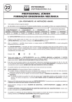
Session S2G
A Microcontroller Laboratory Hardware Platform for
the Academic Environment:
The UDM-EVB
Tom Stoltz 1, Mark Paulik2 and Nizar Al-Holou3
Abstract - The MC68HC11 has been very popular in the
academic environment, succeeded by the 68HC12.
Freescale (formerly Motorola) has introduced the HCS12
family of processors which obsoletes the 68HC11/12. The
University of Detroit Mercy, as part of a master's thesis
project, developed a new laboratory evaluation board
(UDM-EVB) specifically designed for use in the academic
environment. The Freescale HCS12 was selected as the
processor of choice based upon the rich history of
academic support for the 68HC11 and 68HC12. The
UDM-EVB was designed as a single platform including an
HCS12 target processor, a separate debugger, on-board
power-supplies, and fault protected I/O circuits. This
paper will address the trade-offs that exist between
educational functionality, cost, robustness, and how
satisfactory compromises were made in designing the
UDM-EVB. The University of Detroit Mercy is working
to make the UDM-EVB platform and a companion
laboratory manual available to other academic institutions
and industry.
Index Terms - Evaluation board, HCS12, Microcontroller
laboratory.
INTRODUCTION
The pervasive nature of microprocessors and microcontrollers
in nearly every industry segment underscores the necessity for
electrical and computer engineering and science curriculums
to include a fundamentals of microprocessors course which
covers assembly language programming and peripheral
interfacing. Hands-on laboratory experience is key to student
knowledge retention and the ability to apply that knowledge in
practical endeavors. Debugging software and hardware in the
lab environment enhances student understanding beyond the
basic knowledge of computer operation.
A significant challenge to the academic community is
the obsolescence rate of computer laboratory hardware. The
university has been using 68HC11 and 68HC12 development
boards for the last decade. In 2003, the University of Detroit
Mercy began developing a new microcontroller hardware
evaluation board with the following goals:
• Specify a hardware platform based on the newest
available technology with a clear roadmap for future
product support. The evaluation board shall be selfcontained and provide sufficient experimental flexibility.
• Design a hardware platform robust enough to withstand
student handling and simple enough to operate without
excessively compromising experimental flexibility.
• Leverage industrial partnerships to manufacture the
hardware platform and make the platform available to
other institutions in a cost effective manner.
• Develop an introductory microcontroller laboratory
course requiring minimal infrastructure changes. The
laboratory must be self-contained to the extent that lecture
content and flow is relatively independent of the
laboratory experiments, and general enough to adapt to
many different microcontroller texts and lecture topical
organizations.
The University of Detroit Mercy developed a new
laboratory evaluation board, the UDM-EVB, based on the
Freescale (formerly Motorola) HCS12 processor. The product
specifications and hardware design were completed by the
authors as a master’s degree thesis project [1]. Motorola
Semiconductor manufactured a small production run of UDMEVBs. A newly developed course with supporting lab manual
is currently in its fourth term offering. This paper will discuss
the design trade-offs, lessons learned, lab/lecture philosophy,
and current status for availability to other academic
institutions.
LABORATORY HARDWARE REQUIREMENTS
The authors postulate that proficient fundamental knowledge
of any instruction set architecture and embedded
microcontroller peripheral interface enables students to
quickly adapt to any processor or platform. Assuming skill
portability, one may argue that using dated hardware such as
the 68HC11, in no way detracts from the educational
1
Tom Stoltz, Design Engineer, STM Power, Inc. Ann Arbor, Mi 48101, [email protected]
Mark Paulik, Professor, University of Detroit Mercy, Electrical and Computer Engineering, Detroit, Mi 48219, [email protected]
3 Nizar Al-Holou, Professor and Chair, University of Detroit Mercy, Electrical and Computer Engineering, Detroit, Mi 48219, [email protected]
2
0-7803-9077-6/05/$20.00 © 2005 IEEE
October 19 – 22, 2005, Indianapolis, IN
35th ASEE/IEEE Frontiers in Education Conference
S2G-1
Session S2G
efficiency of a microcontroller laboratory. In practice there are
a few limitations to old hardware:
• Hardware degrades and replacements become difficult to
procure.
• Textbooks are removed from print as texts supporting
new processors become available. Development tools
become obsolete (e.g., MS-DOS based applications).
• Antiquated hardware fails to take advantage of higher
processor speeds, larger memory spaces, and newer
peripherals such as CAN networking.
Many schools around the country are still using an obsolete
microcontroller platform such as the 68HC11 in their
laboratory. A few schools have started to upgrade their
microprocessor/microcontroller courses to more recent
platforms. For example, Iowa State faced a similar hardware
upgrade challenge and chose the PowerPC based Freescale
MPC555 processor for a new laboratory environment [2].
Given the plethora of embedded processor options on the
market today including Microchip’s PIC processor, the 8051,
and 6800 derivatives, selecting a processor is a key decision.
Iowa State chose a high-end processor with a C development
environment for a new lab platform. A trade-off exists
between teaching processor architecture and programming
fundamentals and using more powerful processors and tools.
The University of Detroit Mercy selected the Freescale
HCS12 processor with basic tools and an exclusively
assembly code based introductory lecture/lab. For our
particular program and constituencies, this choice has proven
very effective. The following considerations support the
decision:
• The HCS12 D-family is too complex for introductory
usage. The rich peripheral set provides so many options
students quickly become overwhelmed. The HCS12
documentation is modular such that a reduced peripheral
set can be studied while “hiding” the more advanced
peripherals of the MC9S12DP256C from the students
unless they are needed. The MPC555 complexity dwarfs
the already complex HCS12. The user manual is over
1,000 pages, and device configuration is quite complex.
The key skill students must learn to be effective in
embedded systems is the ability to read and use the device
documentation. Teaching basic peripherals with concise
documentation provides the skills necessary to move to
any other processor. Use of high-end devices can cause
students to rely on code templates and drivers rather than
understand device configuration at the register level.
• All computers ultimately execute machine code.
Assembly language is the lowest human-readable level at
which computers may be effectively studied. Teaching
students the fundamentals of machine code, fetch and
execute processing, and register manipulation provides a
basis to understand computer architecture, code
optimization, complier design, and hardware construction.
The most compelling argument for the use of assembly
code for an entire semester came from a survey of Ford
powertrain control engineers. One software technical
specialist stated that he didn’t care what platform a
student learned assembly on, “as long as they learn
assembly.” Far too many engineers in his experience
know C fluently, but can’t poke around at the assembly
level during code tracing and debugging. When the
system doesn’t work as intended, going below the C-level
is a critical skill. Additionally, peripheral interfacing is a
key part of an introductory microcontroller course.
Register configuration code is largely independent of the
programming language. Teaching the entire course in
assembly simplifies the tool set students are required to
learn, allowing them to focus on understanding the
fundamentals of debugging, peripheral configuration and
interfacing that are language and platform independent.
The University of Detroit Mercy also offers an advanced
(senior/graduate) embedded systems course that utilizes C
and Forth to implement real-time tasks and demonstrate
the interface between a high-level language and assembly.
The advanced course uses the UDM-EVB for the first
third of the course to teach advanced peripherals
(enhanced timers and SPI), then progresses to a robot
based platform with a low-cost Technological Arts
HCS12 EVB.
• The HCS12 contains sufficient memory (12k RAM) for
just about any undergraduate application (even in C or
other high-level languages), with the exception of data
intensive applications. The CPU12 instruction set is based
on a median CISC Van Neumann architecture. Briefly
contrasting the CPU12 instruction set with the RISC,
Harvard architecture Microchip PIC provides the student
with a representative overview of processor architectures.
The HCS12 is very cost effective to implement in other
student projects with small stand-alone EVBs.
The UDM-EVB is unique when contrasted with other
commercially available products. The UDM-EVB has been
specifically designed as a complete, robust, stand-alone
development system, for teaching an introduction to
microprocessors and microcontrollers undergraduate course.
Many standard EVBs include switch or LED I/O, but few
include a mix of peripheral devices specifically chosen to
support a 15-week university course. The UDM-EVB includes
two microcontrollers on one EVB, allowing pod mode
debugging without separate hardware. The UDM-EVB
circuitry is designed to be electrically robust in the hands of
the students, while most EVBs are damaged by common
student errors.
Selecting a debug toolset is as critical as the processor
selection, and largely constrained by the processor choice.
Debug-12 is a monitor program that succeeds the Buffalo
serial monitor debugger. A simple serial ASCII text monitor
program is a viable choice for a couple reasons:
• Debug-12 is freely available and well supported.
• Students that learn to debug with a simple debug tool tend
to adapt quickly to more sophisticated GUI-IDE based
tools while students that begin on a high-end tool tend to
0-7803-9077-6/05/$20.00 © 2005 IEEE
October 19 – 22, 2005, Indianapolis, IN
35th ASEE/IEEE Frontiers in Education Conference
S2G-2
Session S2G
struggle to use simple tools sets when availability dictates
their use.
Typical serial monitors reside on the target processor under
test. While Debug-12 supports target resident operation, it also
supports a POD mode. In POD mode, Debug-12 operates on a
HCS12 processor separate from the target processor running
the code under investigation.
The HCS12 contains a
Background Debug Mode (BDM) single wire interface that
allows significant debugging power in a simple package.
BDM frees 100% of the target processor memory and
peripherals for application use, and allows memory to be
viewed and modified while the processor runs at full speed.
Pod based debugging also supports all the breakpoint, trace,
load, and register control options of a resident monitor
program. One significant advantage of using a separate pod
processor is in teaching interrupt operation. Interrupt vector
re-mapping is a common technique to allow students to create
interrupt code while sharing the processor with the debug tool.
The HCS12 allows RAM to be re-mapped in the memory
space, so RAM can overlay the interrupt vector table, and the
students can write RAM executed code that uses the native
interrupt vectors. Removing the debug tool from the loop
allows students to trace through interrupt operation, and avoid
the confusion of extra layers of abstraction.
Using a separate Pod processor typically requires two
evaluation boards per lab station, so a design goal of the
UDM-EVB was to integrate a “2-for-1” solution with a
dedicated pod processor resident on the same evaluation board
as the target processor. The second processor increases the
hardware cost of an evaluation board by about $20 (compared
to $80 for a separate EVB); a relatively small price for the
power of BDM pod-based debugging. Additionally, single
wire or serialized debugging interfaces such as BDM, JTAG,
and Nexus are replacing logic analyzers and emulation pods in
embedded systems development shops; therefore, teaching
BDM debug is a valuable skill.
Most evaluation boards provide minimal processor support
with limited peripherals. External I/O hardware is required.
The UDM-EVB design philosophy was to provide a broad
range of interesting I/O devices. Most of the I/O devices are
not dedicated to port pins, allowing off-board I/O to be
connected to the target processor, or allowing the I/O to be
used with another target system. To meet the design
objectives, the following peripheral selection was chosen:
• Digital inputs: Four latched and four momentary pushbuttons for user input.
• A/D inputs – Dual potentiometers and an 800 Hz triangle
wave generator.
• PWM / Timer digital I/O: A DC fan with optical speed
measurement and (4) one-amp ground side over-current
protected FETs for user load control (including uni-polar
stepper motors). The PWM port also contains a Red,
Green, Blue LED with individual PWM intensity control
of each color.
• Digital Outputs: Dual 7-segment BCD LED displays
• Bit-wise LED state indicators on all bi-directional Port
Pins (except Port B with 7-Segment I/O).
•
•
•
•
•
Analog Outputs: A 4-channel SPI D/A converter and a
speaker with a 1 Watt amplifier.
SPI: A 16kB EEPROM for bi-direction SPI
communication.
Data Communications: The DeBug12 pod processor
contains one dedicated RS-232 port for communication
with the monitor program. The target processor contains
two RS-232 ports. The target contains one Automotive
High-Speed CAN interface, and connection points for a
protected IIC interface.
The dedicated BDM debug pod is available to connect to
external targets.
A solderless proto-board is attached to the base plate,
adjacent to the user accessible pin strip, making the board
a self-contained development environment.
DESIGN FOR STUDENT USAGE
Development tool reliability tends to be a problematic issue
with microcontroller evaluation boards, especially in the hands
of inexperienced students. Dysfunctional hardware
complicates laboratory activities and detracts from educational
opportunities. Keeping microcontroller evaluation boards
functional often becomes a significant task for the lab faculty.
One key design consideration for the UDM-EVB was to
evaluate past hardware issues, identify the student usage
profile, and incorporate a reasonable degree of protection.
Electrical failure is the most common fault mode in a lab
environment. Three major sources of electrical failure were
identified:
• Providing incorrect power supply to the processor
including reverse polarity or the wrong voltage. Many
EVBs don’t contain an on-board power supply, so reverse
polarity or excessive supply voltage will destroy the
processor very quickly.
• Shorting output lines to power or ground resulting in
excessive current. Most consumer products are designed
such that no sequence of commands will result in
hardware damage. EVBs are typically not so forgiving.
Students may intend to provide a grounded input, for
example, but inadvertently configure the port data control
register as an output with a logic high. The resultant
condition will damage the output or the entire processor.
• Electrostatic discharge is the silent killer of CMOS
devices. Students routinely connect wires to
microcontroller pins, without properly grounding
themselves.
Mechanical and electro-mechanical failure modes are
less prevalent, but do occur. For example, damage may occur
due to excessive board flex while mating wide ribbon cable
connectors, or due to objects dropped on the circuit board
(including conductive objects) while the board is operating.
The UDM-EVB key constraints were to design a
board that didn’t excessively limit external device interfacing,
was cost effective, and robust relative to the student usage
profile. Several compromises were necessary. Cola beverages
spilled on an EVB are an age-old issue, commonly countered
by restricting refreshments in the lab. The UDM-EVB could
0-7803-9077-6/05/$20.00 © 2005 IEEE
October 19 – 22, 2005, Indianapolis, IN
35th ASEE/IEEE Frontiers in Education Conference
S2G-3
Session S2G
have been conformal coated to provide a moisture barrier and
cola protection, but complete conformal coating would
interfere with the connector interfaces, and selective
conformal coating is generally labor intensive and thus not
cost effective. The goal was never a “Student-proof” board,
but rather a board that would handle the majority of expected
student usage profiles. A failure-mode effects analysis
(FMEA) approach was utilized where severity and probability
of occurrence were ranked against cost of mitigation.
A major distinction between the UDM-EVB and most
other EVBs is circuit protection. All user I/O is interfaced
through carefully segmented and marked I/O pins. Each I/O
pin contains over-current and ESD protection, as well as an
LED state indicator to eliminate the need for logic probes. The
UDM-EVB I/O circuitry is designed such that a short circuit
between any user pin and any power-source from –15V to
+15V will not result in damage to the EVB, even if the pin is
configured as an output. The protection circuitry limits the
drive strength and bandwidth of the peripheral interface, but
the board is capable of maintaining CMOS logic levels at
about 1mA, and with a 5 kHz bandwidth. The circuit
protection precludes the use of bas-based interface
experiments, but permits most sensor and actuator
experiments with little risk to the hardware.
mechanical protection, and the circuit board is fastened to a
rigid 1/8” thick fiberglass panel to prevent flexing. The boards
may be stacked without mechanical damage.
UDM-EVB HARDWARE
The University of Detroit Mercy partnered with Motorola
Semiconductor early in the design cycle. The University
provided the design within certain manufacturing limitations,
and manually assembled and validated two prototypes.
Motorola provided all materials and funded a small production
run of 50 units. The university upgraded their microcontroller
lab with part of the build, and Motorola took several units to
upgrade their internal classes. The design has been
successfully intergraded into the curriculum. Discussions are
underway both with Freescale and a third party tool vender to
make the UDM-EVB available at a reasonable cost to other
institutions. The initial target price was $350 - $400. The
hardware build cost is significantly less than the target, and
given reasonable considerations for warranty and distribution
cost, the board may be made available at or below the design
target depending on the level of interest and projected volume.
UDM-EVB LABORATORY MANUAL
The University of Detroit Mercy currently offers two
dedicated microcontroller courses with associated three hour
labs - EE387: Introduction to microcontrollers, a junior level
course, and EE579: Embedded Systems, a graduate course. At
the time of publication, EE387 has been offered twice,
utilizing the UDM-EVB for the entire 15-week course. EE579
has been offered once, and utilized the UDM-EVB for the first
half of the course, and used the UDM-EVB debug pod in
conjunction with a low-cost Technological Arts HCS12
evaluation board [3] for a student robotics project (another
course, EE487, also used the board for a semester). The
hardware has performed within expectations, with virtually no
hardware issues or significant limitations being identified.
The lab manual was developed so as to require minimal
lecture support, and remain independent of course text
selection [4 – 8], without attempting to duplicate the
instructional depth of a full lecture or text. The lab manual
consists of 10 chapters – There are three two-week labs, and
provisions for a mid-term lab exam. Each chapter begins with
The UDM-EVB also incorporates two 5-volt power
a pre-lab reading assignment that provides a few pages of
supplies. The on-board logic power supply is an automotive
background and technical knowledge for the assignment. Each
grade supply, providing reverse supply protection to -14 volts,
lab then provides two exercises. The first exercise is a cookas well positive regulation up to 27 volts. The supply is
book, detailed procedure where the students are required to
thermally protected, and the on-board Fan, used as an I/O
execute the various steps and make certain observations. The
experiment for PWM speed control defaults to the on state and
exercises typically allow the student to manually configure the
is strategically located to provide power supply cooling for
peripherals, and observe their operation. The second exercise
additional design margin. Power for user experiments is
is a design exercise requiring the students to generate an
provided via a separate tracking regulator. The regulator is
assembly program to meet certain requirements. The design
capable of supplying 200mA with less than 10mV of error
exercise typically requires student effort outside the normal
with respect to 5.000V, but is isolated such that excessive
three-hour lab session. A software code template is provided,
voltage inadvertently applied to the user circuitry does not
and professionalism and documentation is stressed throughout.
back-feed the processor and cause damage. The design
To encourage systematic design, the lab manual is written to
includes provisions for a clear plastic cover to provide
support a top-down design approach. Initially, the lab provides
0-7803-9077-6/05/$20.00 © 2005 IEEE
October 19 – 22, 2005, Indianapolis, IN
35th ASEE/IEEE Frontiers in Education Conference
S2G-4
FIGURE 1: UDM-EVB LAYOUT
Session S2G
the design requirements, flow-chart, and assembly code, and
the students are required to assemble and run the program.
Each successive lab moves one step up the design hierarchy,
encouraging students to code from a provided flow-chart, then
ultimately develop a flow-chart and code a solution from a
high-level specification. From a pedagogical point of view,
the use of the UDM-EVB and the described laboratory
structure provides a consistent, contextual, and progressive
experience for the students. They have the opportunity to
revisit topics at increasing complexity levels which serves to
re-enforce concepts.
The integrated and consistent
experimental environment provided by the UDM-EVB
platform allows students to focus on concept development as
they experience comprehensive exposure to microcontroller
peripheral design and usage.
TABLE I
LAB MANUAL ORGANIZATION
1
2
3
4
5
6
7
8
9
10
Lab Title:
Introduction to UDM-EVB, DeBug12, .s19 files and machine code
Assembly and Debugging
Software Documentation, Programmer’s Model, and Addressing Modes
Branches, Loops and ASCII
Subroutines
Port I/O – Switch inputs and LED / BCD outputs
Analog to Digital Conversions
Interrupts
Serial Communications (SCI) (2 weeks)
Timers and Pulse Width Modulation (2 weeks)
One perennial problem with lab assignments is project
re-use between lab teams and years. To reduce the occurrence
of academic dishonesty, each lab project contains ten
variations. For example, the port I/O lab requires the students
to code a light chaser. Each team is responsible for a different
light sequence, making code re-use more difficult. Each
project variation provides identical learning outcomes, and is
roughly equivalent in difficulty.
The initial course offering attempted a classical lecturelead-lab approach. The students would receive the theory
background and understanding in lecture, then see the theory
in operation in the subsequent lab. Coordinating the lecture
and lab schedules proved to be challenging, as the lab seemed
to always progress faster than the lecture (partially due to time
lost for assessment, as well as course text structure). During
the second offering, the instructional team decided to attempt
a progressive lab-lead-lecture approach (based on just-in-time
learning paradigms). Since the lab always seemed to pullahead of the lecture, we decided to stop fighting the tendency,
and utilize a discovery or enquiry-based learning pedagogy.
The students would receive preliminary background
instruction in the lab, and carry out the lab procedure. While
the students didn’t understand all the principles at the time
they conducted the experiment, the observations made in lab
increased the relevance and interest in the lecture. Based on
student feedback obtained via formal oral reviews and end of
semester, qualitative outcome assessment surveys, as well as
instructor observations, this approach was successful, and will
be continued in the future. The lab-lead-lecture approach
requires skilled instructional support in the lab to provide 20 –
30 minutes of explanation. Also, since students effectively
encounter problems they are initially unprepared for,
laboratory faculty must be able to guide the enquiry process
and help the students assume responsibility for their own
learning. The lab-lead-lecture approach is the subject of
further study at the University of Detroit Mercy and may
result in a paper specifically addressing this method in the
future.
CONCLUSIONS AND NEXT STEPS
The emerging embedded systems focus in the ECE curriculum
at UDM is consistent with local industry needs without
compromising the fundamental breadth and depth necessary
for graduate study. The UDM-EVB serves as a key
component in the restructured microcontroller laboratory
courses. By leveraging industrial partnerships, we have
developed a product specifically optimized for student lab
usage. Experimentation with the sequencing of material
presented to students has resulted in an instructional model
similar to just-in-time and enquiry-based methods, that can be
easily adapted to most electrical engineering programs. From
the project’s conception, the UDM-EVB roadmap called for a
cost effective product to be developed that would be
accessible to the larger academic community. Minimal effort
remains in commercializing both the UDM-EVB and the lab
manual. Institutions interested in adopting the UDM-EVB and
the associated lab manual are encouraged to contact the
authors.
ACKNOWLEDGMENT
From Motorola Semiconductor Product Sector: Neil Krohn for
committing to support the University in developing the UDMEVB, Tom Richardson, Boyd Beckington, and Munir
Bannoura for technical reviews, Daniel Beeker for technical
reviews and managing the UDM-EVB manufacturing effort,
and Dave Dunayczan for providing a tremendous amount of
interest and support for the project, and facilitating many of
the Motorola meetings. From Ford Motor Company,
Powertain Control Systems Engineering: Chris Falco, for
authorizing and supporting my MSEE studies, Kiana
Whitehead, Keith Putnam, Adrian Petrut and Sasha Cejic for
technical reviews, and countless other co-workers who put-up
with my obsession. From Motorola Automotive Electronics:
Roy Hunninghaus, Gary Stefanik, Josh Love, and Mike Moroz
for technical reviews, and Chris Glennon for the PCB review.
From Visteon Corporation: Kathy Walsh and Gordan Juresak
for technical reviews and John Sinelli for arranging the
partnership with Motorola SPS. Finally, the authors would like
to extend their appreciation to the junior and senior students
that piloted the microcontroller laboratory.
0-7803-9077-6/05/$20.00 © 2005 IEEE
October 19 – 22, 2005, Indianapolis, IN
35th ASEE/IEEE Frontiers in Education Conference
S2G-5
Session S2G
REFERENCES
[5]
R. Haskell, Design of Embedded Systems Using 68HC12/11
Microcontrollers, Upper Saddle River, NJ: Prentice Hall, 2000.
[6]
Valvano, Jonathan, Embedded Microcomputer Systems: Motorola 6811
and 6812 Simulation, Pacific Grove, CA: Brooks/Cole – Thomson
Learning, 2003.
[1]
Stoltz, Tom, "Development Of A Motorola HCS12 Microcontroller
Hardware Development Platform Optimized For Use In A University
Environment", A Master’s Thesis, University of Detorit Mercy, May
2003.
[7]
[2]
A. Striegel and D. Rover, “Enhanced Student Learning in an
Introductory Embedded Systems Laboratory”, Proc. 32nd ASEE/IEEE
Frontiers in Education Conference, Boston, MA, Nov. 2002.
G. J. Lipovski, Introduction to Microcontrollers, Second Edition, New
York, NY: Elsevier Academic Press, 2004
[8]
D. Pack and S. Barrett, 68HC12 Microcontroller Theory and
Applications, Upper Saddle River, NJ: Prentice Hall, 2002.
[3]
Technological Arts Website, http://www.technologicalarts.com/
[9]
Oliver Thamm’s HC12 web, http://www.elektronikladen.de/hc12/.
[4]
G. Doughman, Programming the Motorola M68HC12 Family, Poway,
CA: Annabooks, 2000.
0-7803-9077-6/05/$20.00 © 2005 IEEE
October 19 – 22, 2005, Indianapolis, IN
35th ASEE/IEEE Frontiers in Education Conference
S2G-6