1
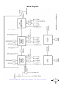
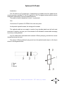
filteredCOFFEE
user manual
manual
user
ANALOGUE SOLUTIONS FC
e&oe (c) 3-2002
1
Contents
Specification...................................................................................................................... 3
Circuits .............................................................................................................................. 3
Introduction ........................................................................................................................ 4
Apllications ........................................................................................................................ 4
Safety Instructions .............................................................................................................. 5
Mounting ............................................................................................................................ 5
Quick Start Guide .............................................................................................................. 6
Block Diagram................................................................................................................... 7
Controls In Detail ............................................................................................................... 8
INPUT LEVEL ................................................................................................................... 8
ENVelope FOLloW LEVEL ............................................................................................... 8
LFO1 SPEED / LFO2 SPEED .......................................................................................... 8
High Pass Filter ................................................................................................................. 8
RESOnance ...................................................................................................................... 8
CV1 LEVEL ...................................................................................................................... 8
CV2 LEVEL ...................................................................................................................... 8
CUTOFF ............................................................................................................................ 8
Low Pass Filter .................................................................................................................. 8
RESOnance ...................................................................................................................... 8
CV1 LEVEL ...................................................................................................................... 9
CV2 LEVEL ...................................................................................................................... 9
CUTOFF ............................................................................................................................ 9
AUDIO IN LEVEL .............................................................................................................. 9
VCA .................................................................................................................................. 9
Bypass Switch ................................................................................................................... 9
CV1/2 LEVEL ................................................................................................................... 9
OUTPUT VOLUME .......................................................................................................... 10
Rear Panel ...................................................................................................................... 11
POWER IN ...................................................................................................................... 11
SIGNAL IN ....................................................................................................................... 11
SIGnal IN THRU ............................................................................................................... 11
ENVelope OUT ................................................................................................................ 11
PEDAL IN ........................................................................................................................ 11
PEDAL CV OUT .............................................................................................................. 11
LFO1 OUT ....................................................................................................................... 11
LFO2 OUT ....................................................................................................................... 11
HPF CV IN ....................................................................................................................... 11
HPF SIGnal OUT ............................................................................................................. 12
LPF SIGnal IN .................................................................................................................. 12
LPF CV IN ....................................................................................................................... 12
VCA SIGnal IN ................................................................................................................. 12
VCA CV IN ...................................................................................................................... 12
SIGNAL OUT ................................................................................................................... 12
Optional CV Pedal ........................................................................................................... 13
Description of sections .................................................................................................... 14
ENV FOLW (Envelope Follower) ..................................................................................... 14
LFO ................................................................................................................................. 14
VCA ................................................................................................................................ 14
HPF ................................................................................................................................. 14
LPF ................................................................................................................................. 14
ANALOGUE SOLUTIONS FC
e&oe (c) 3-2002
2
Specification
Rotary Controls:
15
Toggle Switches:
7
Push/Pull Switches:
3
LEDs:
3 - red, yellow, green
Jack Sockets (6.35mm)
14
Size:
1U
Weight:
Power
15V AC input, 500mA
Circuits
Envelope Follower
Low Frequency Oscillator x 2
High Pass Filter (12dB/oct)
Low Pass Filter (12dB/oct) - combined with the HPF produces a Band Pass Filter
Voltage Controlled Amplifier
The HPF, LPF, VCA, and Env. Follower are accurate clones of the Korg MS20
synthesiser which has a distinct sound.
ANALOGUE SOLUTIONS FC
e&oe (c) 3-2002
3
Introduction
Congratulations on buying the Phobos Filtered Coffee.
The Filtered Coffee (FC) is part of the Phobos range of music machines, which includes the Black Coffee analogue monosynth and the
Oberkorn analogue sequencer.
The FC is a versatile filter effects unit whose filter circuits are based
on the legendary Korg MS20 monosynthesiser which has a unique and
distinctive sound. Any audio source can be used with the FC.
The FC has been made to provide a high number of flexible modulation routings to allow many filter effects to be created.
The FC can produce anything from subtle filter sweeps right up to
howling, screaming distorted doings. It can also take standard acoustic
type sounds and make them ‘analogue’ - e.g. play ‘real’ drums through it
and get analogue percussion out the other side.
Two FCs can easily be combined to produce stereo filter effects
and auto-panning between speakers. This is easily achieved by linking
the audio source and the LFO signals using the rear jack sockets.
The FC is based on analogue circuitry, it does not rely on processor
speed or software updates, so it’s value will keep for far longer than its
digital counterparts.
Apllications
•
•
•
•
•
•
an extra effects module for modular synthesisers
versatile analogue studio effects unit
live use for DJs and bands
bringing life to dull sounds
making digital sounds more ‘analogue’
guitar effects unit
many more!
Any audio input can be used - synthesiser, sampler, microphone,
guitar, mixer effects send, drum machine, bass guitar, CD player, DJ mixing decks, anything!
ANALOGUE SOLUTIONS FC
e&oe (c) 3-2002
4
Safety Instructions
Please read carefully before using:
• Only use the recommended power adaptor - 15V AC, 500mA
• Never handle the adaptor with wet hands
• Never excessivly bend the adaptor cable, or get it trapped or place heavy objects on
it. If the adaptor cable becomes damaged, replace the adaptor.
• Ensure the unit is disconnected from the mains before moving or cleaning.
• Always disconnect the unit from the mains if there is lightning in your area.
• Ensure the unit is on a stable surface, and never place heavy objects on top of it.
• Never allow young children to operate the unit or adaptor.
• Do not use excessive force when using the controls or inserting cables to the connectors.
• The Unit should not be operated in the rain or near water and should not be exposed
to moisture. If the unit is brought from a cold environment to a warm one, the unit should be left
to reach the ambient temperature. This is to allow any possible condensation moisture inside
the unit to evaporate. Although any built up moisture will not damage the unit, any shorting
may be hazardous.
• Never open the case or attempt to make repairs. Refer any servicing to a qualified
service personnel.
Mounting
The FC can be rackmounted in any standard 19” rack case. It requires only 1U, and very
little depth. Alway use all 4 mounting holes so it is secured in the rack.
Alternatively, just place the unit on a stable surface. Rubber feet can be stuck on the
base to stop it sliding about.
ANALOGUE SOLUTIONS FC
e&oe (c) 3-2002
5
Quick Start Guide
This section is intended for those who just want to quickly plug in the unit and get going;
•
•
•
•
•
•
Ensure the unit is switched off
Plug you audio input to the rear panel Audio In socket
Plug the rear panel Audio Out socket to your mixer
Turn the input level and output volume controls to minimum
Set up your mixer levels as appropriate
Power up the unit
•
•
•
•
Turn the LPF AUDIO IN LEVEL pot to maximum
Move IN/BYP switch to IN
Move the VCA switch 2 to THRU
Turn the VCA CV1/2 LEVEL control to maximum
• Turn the HPF CUTOFF control to minimum
• Turn the LPF CUTOFF control to maximum
• Set the main output level to around 50%
Now, slowly increase the INPUT LEVEL. A signal should start to be heard. The INPUT
LEVEL needs to be adjusted as high as possible without distortion (unless you require distortion as this can be a useful effect). You will need to balance the OUTPUT VOLUME so you
do not overload your mixer.
Now you should be up and running witha fairly un-effected signal. Remember, this is an
analgue effect based on a vary old discrete circuit, so some colouration of even an uneffected
sound is possible!
Play around with the other controls for nice filter effects.
With digital effects, there are a wide range of presets. You switch the unit on and will
instantly be wooed by the stunning DSP effects.
Analogue effects units do not have presets. Depending where the knobs are set to, you
may switch the unit on and get a very dull and uninspiring sound. The FC can produce a wide
range of filter effects, most are fantastic, but some you may not like. You will need to play
around with it for a while till you learn how to get the best out of it. As you become familiar with
the unit you will soon find out the best settings for your tastes.
ANALOGUE SOLUTIONS FC
e&oe (c) 3-2002
6
Block Diagram
ANALOGUE SOLUTIONS FC
e&oe (c) 3-2002
7
Controls In Detail
INPUT LEVEL
This control sets the input level of the signal fed into the Audio In socket. At higher
settings it is possible to overload the input signal for a distorted sound if required.
ENVelope FOLloW LEVEL
This control sets the sensativity of the Envelope Follower. At higher settings, a larger
ENV follower signal will be obtained.
LFO1 SPEED / LFO2 SPEED
These controls set the 2 LFO frequencies.
High Pass Filter
RESOnance
This control sets the resonance level. A higher setting increases the intensity of the
resonance. At very high settings it is possible to self-oscillate the filter.
CV1 LEVEL
This control sets the amount the CV source selected via the switch will modulate the
HPF cut-off frequency: The source switch has 3 options; LFO1 (up), Off/no signal (centre),
PEDAL (down)
LFO1
LFO1 is used as the source
center
no signal is routed (no modulation effect)
PEDAL
if a CV pedal is being used, this is the source
CV2 LEVEL
This control sets the amount the CV source selected via the switch will modulate the
HPF cut-off frequency. When this switch is pulled out, the CV source is inverted - so the
positive signal is flipped over. This is ideal so you can have, for example, the LPF sweeping up whilst the HPF is sweeping down. The source switch has 3 options; Env (up), Off/no
signal (centre), LFO2 (down)
ENV
The ENV follower is the source
center
no signal is routed (no modulation effect)
LFO2
LFO2 is used as the source
CUTOFF
This control sets the cut-off frequency. As the setting is increased, more and more
lower frequencies are filtered out.
Low Pass Filter
RESOnance
This control sets the resonance level. A higher setting increases the intensity of the
resonance. At very high settings it is possible to self-oscillate the filter.
ANALOGUE SOLUTIONS FC
e&oe (c) 3-2002
8
CV1 LEVEL
This control sets the amount the the CV sources selected via the switch will modulate
the HPF cut-off frequency. When this switch is pulled out, the CV source is inverted - so the
positive signal is flipped over. This is ideal so you can have, for example, the LPF sweeping up whilst the HPF is sweeping down. The source switch has 3 options; LFO1 (up), Off/
no signal (centre), PEDAL (down)
LFO1
LFO1 is used as the source
center
no signal is routed (no modulation effect)
PEDAL
if a CV pedal is being used, this is the source
CV2 LEVEL
This control sets the amount the CV source selected via the switch will modulate the
HPF cut-off frequency. When this switch is pulled out, the CV source is inverted - so the
positive signal is flipped over. This is ideal so you can have, for example, the LPF sweeping up whilst the HPF is sweeping down. The source switch has 3 options; ENV (up), Off/no
signal (centre), LFO2 (down)
ENV
The ENV follower is the source
center
no signal is routed (no modulation effect)
LFO2
LFO2 is used as the source
CUTOFF
This control sets the cut-off frequency. As the setting is increased, more and more
higher frequencies are filtered out.
AUDIO IN LEVEL
This control sets the audio in level to the LPF (following the output of the HPF). This
control must not be at zero to hear some effect. In normal use leave it at maximum. Use it to
adjust the audio in level when using the LPF Audio In socket on the rear panel.
VCA
Bypass Switch
The filter effects can be switch in (IN) or out (BYPassed). This allows you to compare
the unprocess input signal and the final processed signal for comparison.
IN (switch up)
The effect is switch IN. The signal at the output socket is the processed signal.
BYPass (switch down)
The input signal is directly routed to the output signal and the filters have no effect.
The processor is literally bypassed.
To hear any effect of the filters/VCA the switch must be at the IN position.
CV1/2 LEVEL
This control sets the amount the CV1/2 sources selected via the switches will modulate the VCA level.
The CV1 source switch has 3 options; ENV (up), Off/no signal (centre), LFO1 (down)
ENV
The ENV follower is the source
center
no signal is routed (no modulation effect)
THRU
The VCA is held open at a level near full volume
ANALOGUE SOLUTIONS FC
e&oe (c) 3-2002
9
The CV2 source switch has 3 options; LFO2 (up), Off/no signal (centre), inverted
LFO2 (down)
LFO2
LFO2 is used as the source
center
no signal is routed (no modulation effect)
-LFO2
LFO2 is inverted and used as the source
To hear any processed signal at the output socket, the VCA must be active by applying
CV. The CV 1/2 LEVEL control must be used in conjunction with the CV source switched.
OUTPUT VOLUME
This control sets the final main output level.
CV Signal Inverters
HPF CV Level 2, LPF CV Level 1 and LPF CV Level 2 all have built in push-pull on/off
switched. When the knob is pulled out, the CV signal is inverterd (up-side-down).
This is a useful feature for when you want the LPF and HPF sweeping in opposite
directsion when using the same CV source.
For example, if LFO2 is the source for CV modulation of the 2 filters, if the LPF CV
Level knob is pulled out, then as the HPF sweeps up, the LPF will sweep down.
I
ANALOGUE SOLUTIONS FC
e&oe (c) 3-2002
10
Rear Panel
Connectors as view from the rear, right to left. The Filtered Coffee
provides un-unusually high number of connection sockets, more commonly
associated with modular synthesisers. The maximum amount of connectivity, space allowing, has been supplied for maximum flexibility.
POWER IN
This unit requires a 15 volt AC signal (not DC!). 500mA minimum.
Although the unit requires AC, the type of plug required is called a ‘2.1mm
DC plug’.
All jack sockets are 6.35mm mono, except the Pedal Input socket
which is a stereo type.
SIGNAL IN
Plug your audio in here. The input will take line level and guitar level
signals without the need for pre-amp. A mic’ source may need to be preamp’ed.
SIGnal IN THRU
This is a direct copy of the input signal, which is made available to be
fed through to other Filtered Coffee’s or other processors. Two Filtered
Coffes can be connected up for stereo use. Note the signal is unbuffered.
ENVelope OUT
The envelope follower CV signal is available here.
PEDAL IN
Plug the optional CV pedal in here. There are notes later if you wish
to source your own pedal.
PEDAL CV OUT
The Pedal signal is turned into a useable CV and is available here.
The range is 0 to 12V.
LFO1 OUT
The LFO1 CV signal is available here.
LFO2 OUT
The LFO2 CV signal is available here.
HPF CV IN
The HPF cut-off can be controlled via an external CV using this socket.
Range is -12 to +12V.
ANALOGUE SOLUTIONS FC
e&oe (c) 3-2002
11
HPF SIGnal OUT
The signal filtered by the HPF is available here, before is is further filtered by the LPF.
LPF SIGnal IN
If you wish to feed a signal through the LPF/VCA only, bypassing the HPF, use this socket.
LPF CV IN
The LPF cut-off can be controlled via an external CV using this socket. Range is -12 to
+12V.
VCA SIGnal IN
If you wish to feed a signal through the VCA only, bypassing both filters, use this socket.
VCA CV IN
The VCA level can be controlled via an external CV using this socket. Range is -12 to
+12V.
SIGNAL OUT
The processed signal is available here. (Unprocessed if the Bypass switch is set to
BYP.
ANALOGUE SOLUTIONS FC
e&oe (c) 3-2002
12
Optional CV Pedal
Introduction
The FC features a CV pedal input. A special kind of variable level foot pedal can be
used to produce a variable CV. The CV range is 0 to 12V. The signal can be routed to various
modulation destinations via the front panel switches.
The pedal is ideal for hands free control, i.e. guitarists!
Use
Connect the CV pedal to CV PEDAL IN on the rear panel.
As the pedal is push forwards, the voltage will increase.
The optional pedal we can supply is made of very durable plastic and will suit most
musicians. However, we have yet to see whether it will withstand unreasonalbe stomping
from heavy metal guitarists!
Any CV pedal that is terminated with a stereo 6.35mm jack plug, and with the correct
internal wiring can be used.
The stereo 6.35mm pedal jack plug must have the potentiometer wiper on the tip as
shown in the diagrams below.
1 Signal
2 12V
3 Ground
ANALOGUE SOLUTIONS FC
e&oe (c) 3-2002
13
Description of sections
ENV FOLW (Envelope Follower)
An envelope follower is a circuit that takes an audio input signal, and produces an output
control voltage that represents the amplitude of the audio input.
This would generally be used so that a VCA level could be controlled by the audio input
level. It can also be used to control the filter cut-off.
The CV LEVEL control will set how sensative the follower is to the input level. The follower LED will indicate when it reacts to a signal.
LFO
A Low Frequency Oscillator is a circuit that produces a repeating waveform. The unit
has 2 indeependent LFO’s each outputing a triangle waveform voltage. The signal can be
used to sweep the filters up and down., or to add tremelo to the output level.
VCA
The Voltage Controlled Amplifier is a device that controls the level or volume of a signal
via a voltage. This way the output level of the unit can be varied with a LFO or cv pedal. If the
VCA is not modulated by any CV, or it is not switched to THRU, no signal will be heard as the
volume will be zero.
HPF
The High Pass Filter is a circuit that can will only let high frequencies through it. It filters
out the lower frequencies. The point at which the lower frequencies are filtered is set by the
cut-off frequency. The roll-off is 12db/oct.
LPF
The LowPass Filter is a circuit that can will only let low frequencies through it. It filters out
the higherfrequencies. The point at which the higher frequencies are filtered is set by the cutoff frequency. The roll-off is 12db/oct.
Together, the LPF and HPF can be combined to be a Band Pass Filter (BPF). This
means a band of frequencies are passed trhough, filtering out the lower and higher frequencies, passed the cut-off points set by the two CUTOFF controls.
Certain combined settings of the LPF and HPF may result in no output signal. This is
because we have not restricted the ranges of the two filters, so it is possibly to filter out all the
signal. The controls are unrestricted to allow maximum flexibility.
ANALOGUE SOLUTIONS FC
e&oe (c) 3-2002
14
Filtered Coffee ‘user manual’
part of the Phobos range by Analogue Solutions
web: www.analoguesolutions.com
email: [email protected]
tel/fax: +44 (0) 1384 35 36 94
post: 56 kingsley road, kingswinford, dy6 9rx, uk
ANALOGUE SOLUTIONS FC e&oe (c) 3-2002
15