1
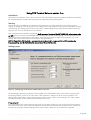
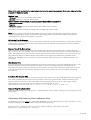
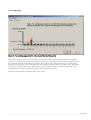
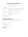
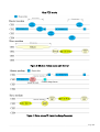
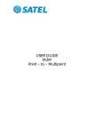
FCS quick note version 3.1
20.06.2005/Jka
_______________________________________________________________________________________________
Free Channel Scan for SATELLINE-3AS/(d) and Epic
A new software version supports FCS with repeater. The receiver automatically selects the stronger signal from the
original master station or the repeater so the coved area is increased. A repeater modem works like a normal
receiver except it repeats all messages. When repeater mode is selected 50% of the available bandwidth is reserved
for the repeater. Both master modem and receivers must be configured with repeater mode “on”. Only one
repeater is allowed.
For new Satelline 3AS and Epic radio modems with E2 marking, Software version 3.15 greater is required. This
new version is compatible with older FCS modem software versions if FCS mode without repeater is selected.
Configuration of modem with software version 3.15 and greater requires FCS Terminal software version 1.0 or
greater. Older FCS Terminal software versions are not compatible.
Free Channel Scan (FCS) is designed for one-way transmission between one transmitter and one or more receivers
when there are at least two different transmission frequencies available. The transmitter monitors the noise level of
the channels between the transmissions and finds the best transmission channel. Software supports maximum of 16
pre selected channels. This feature is beneficial especially when license free channels are used and there could be
other transmitters using the same channels.
To make the usage easier there is a FCS terminal software program for persons with access to a PC. With this
program it is easy to configure the modems to use the FCS function. The FCS Terminal Software reserves the data
port of the radio modem so it is not possible to transmit user data at the same time.
Picture: On the left is label of modem with new logic board. On the right: label of modem with old logic board.
_______________________________________________________________________________________________
Page 1/9
SATEL Oy P.O.Box 142, FIN-24101 SALO, Finland
Street: Meriniitynkatu 17, FIN-24100 SALO, Finland
Tel +358 2 777 7800, Fax +358 2 777 7810, E-mail [email protected]
www.satel.fi
Using FCS Terminal Software version 1.xx
Installation
The FCS terminal software works in PC’s which have one of the following operating systems; Windows 9x, Windows
NT, Windows 2000 or Windows XP. The program is installed by starting FCSsetup.exe.
Starting
Start the FCS Terminal Software and choose the Serial port menu from the upper left corner of the page and
change the settings to match the program menu settings of the radio modem. The program has two pages: Settings
and Scanning. The Settings page can be used to set the suitable settings for the radio modem. With the Scanning
page the user can scan noise levels on each channel.
Note: The FCS terminal software requires that the SL-command function of the SATELLINE-3AS radio modem to be
set ON. See the user manual of SATELLINE-3AS in order to change the general settings. The FCS terminal software
only changes the Free Channel Scan parameters. If you require any other changes to any parameter, e.g. radio
settings, this must be done with the normal SaTerm Terminal Software.
NOTE: When FCS is ON the SL&F= command is not working. SL&F= responds OK, but FCS overrides the
frequency setting. See the FCS related SL commands at the end of this note.
Settings page
Figure 1: Settings page of the FCS Terminal Software for a PC
On the Settings page the same settings must be loaded to all radio modems of the same network noting that the
transmitting modem must be set as “TX master” and the “RX slave” setting is for all the receiving modems. The
settings of the radio modem can be read by pressing, “Read”. Press “Setup” to save settings in to a radio modem.
The network settings can be loaded and saved from the File menu.
Frequency List
The radio modem will use the frequencies put in this list. The radio modem can only accept frequencies inside the
limits of the radio band. If the frequencies added are outside the radio modem’s band range an error message will
be shown when trying to load the settings into the radio modem. Maximum of 16 channels is supported.
_______________________________________________________________________________________________Page 2/9
Note: All the radio modems in the same network must have the same frequencies and in the same order so that the
program will function properly.
Modem Type
- TX Master modem is the transmitting radio modem.
- RX Slave modems are receiving radio modems.
Modem software versions from 3.15 onwards support these additional parameters:
- Master with repeater this must be selected when one modem acts as repeater.
- Repeater
- Slave with repeater this must be selected when one modem acts as repeater.
Remember to switch the setting accordingly when reconfiguring a radio modem.
Note: When using FCS with repeater both Master and slave must be aware of that there might be a repeater
Therefore different setting. When using repeater mode roughly 50% of available bandwidth is reserved for the
repeater(s) so the maximum throughputs is cut to half.
RX Listening Time for Message
This value specifies how long the receiver waits for the transmission on the channel before it changes the channel to
a different one. This time should be more than double of the time between two transmissions or the time between
two beacon transmissions.
Beacon Time If No Data Is Sent
After the beacon time expires the Master radio modem then sends the channel information message (beacon) if
there is not any user data available. With the channel information message the receivers can find the right channel
faster. The suitable beacon time is half or a third of the time between data transmissions. The minimum value must
be greater than 200 ms so that the Master radio modem has enough time to observe the conditions on the
channels. By setting Beacon Time greater than the time between data transmissions no additional beacons are
transmitted.
Max beacon time
If no user data has been sent within Max beacon time beacon transmission is turned off. If Max beacon time is zero,
beacon transmission will not be turned off. This option saves power in battery operation. Disabling beacon
transmission causes the receivers to lose the link to transmitter, and when data transmission starts again, receivers
may lose some of the first transmissions. Max beacon time must be greater than the time between two normal
transmissions.
Free Scan Net ID: (hex ##)
Net ID prevents receivers following a wrong transmitter in the case there are other SATELLINE-3AS radio modems in
FCS mode transmitting on the same frequencies nearby. The receiving radio modem reads the Net ID from the
beginning of the transmission. If the Net ID differs from the programmed Net ID of the radio modem it keeps
changing the channel until it finds the transmission in which the Net ID is correct.
Note: Numbers are in hex format 1-9, A = 10, B = 11, C = 12, D = 13, E = 14 and F =15
Channel Hop Threshold: (dBm)
Channel hop threshold is not used anymore. Signal threshold is used instead as starting value for adaptive channel
hop treshold.
Calculation of RX Listening Time and Beacon Time
The RX listening time must always be greater than the Beacon Time or time between user data transmissions. To set
the RX Listening time and the Beacon Time follow this following formula:
Rx Listening Time = Maximum switch over time (in millisecond format) / the number of channels
Beacon Time = ( Rx Listening Time – 50 ms )/ 2
_______________________________________________________________________________________________Page 3/9
For example: if there are 14 channels and the modem is required to find the correct channel in 7 seconds the
formula would be done as follows:
RX Listening Time = 7000 ms/14 = 500 ms
Beacon Time = (500 ms (RX Listening Time) – 50 ms) /2 = 225 ms (Beacon Time)
Please Note SATEL does not recommend going below 200 ms for Beacon Time. Best recommendation would be
over 250 ms for Beacon Time so there will be enough time to properly check the noise level on each channel.
The transmitting modem (Master) will send information to the slaves prior to the change of the frequency so the
slave modems will usually change to the new frequency with zero switch over time.
_______________________________________________________________________________________________Page 4/9
Scanning page
Figure 2: The scanning page shows the noise levels of the listed frequencies
The Scanning page can be used to analyze the noises of the frequency on the list of the Master radio modem.
Press, “Start” and the program starts to monitor the frequencies. The program does not show the frequencies but
the frequencies located on the lower bar are in the same order as placed on the frequency list. The frequency
settings of the Setup page can’t be loaded to the radio modem when the frequency scanning is ON. The “Read”
and “Setup” stays gray until clicking “Stop” button is pushed and the frequency monitoring has ended. Hop
threshold shows the noise level where the radio modem changes the channel.
NOTE: The “Start” button changes to “Stop” once clicked.
_______________________________________________________________________________________________Page 5/9
Changing parameters with the programming menu
------------------------------------------------------------------------------***** SATELLINE-3AS 3069 *****
SW version 3.14 / HW TC4m
------------------------------------------------------------------------------Current settings
---------------1) Radio frequency
468.20000 MHz ( CF 468.20000 MHz, spacing 25 kHz )
2) Radio settings
TX power 10 mW / Signal threshold -110 dBm / FCS ON /
TX start delay 0ms / Diversity RX OFF / EPIC PWRSave OFF
3) Addressing
RX address OFF / TX address OFF /
RX address to RS port OFF / TX address autoswitch OFF
4) Serial port 1
ON / 38400 bit/s / 8 bit data / None parity /
1 stop bit
5) Serial port 2
OFF / 9600 bit/s / 8 bit data / None parity /
1 stop bit ( RS-232 )
6) Handshaking
CTS Clear to send / CD RSSI-threshold /
RTS Ignored
7) Additional setup Error correction OFF / Error check OFF / Repeater OFF /
SL-commands ON / Priority TX
8) Routing
OFF
9) Tests
OFF
A) Restore factory settings
E) EXIT and save settings
Q) QUIT without saving
Enter selection >
Figure 3: Changing programming menu parameters
To set the parameters of the FCS program press “2”. Note: To ensure the FCS terminal software can be used
properly the SL-commands must be switched ON. (Figure 3, selection 7, Additional setup)
Radio setup
----------1) TX power
10 mW
2) Signal threshold -110 dBm
3) TX start delay
0ms
4) Diversity RX
OFF
5) Epic power save
OFF
6) Free channel scan TX Master / ON
7) View hardware info
Enter selection or ESC to previous menu >
Figure 4: Radio setup
_______________________________________________________________________________________________Page 6/9
Free channel scan settings
---------------------------1) Free scan mode
ON
2) Type of modem
TX Master
3) FreeScan net ID
22
4) Rx change freq
900ms
5) Channel hop threshold -110 dBm
6) Beacon timer
250 ms
7) Beacon max time
0 s
8) Add new frequency to list
9) Show free scan frequency list
A) Clear frequency list
Enter selection or ESC to previous menu >
Figure 5: FCS settings menu
Submenu selections
1) Sets FCS mode ON or OFF.
2) Set the radio modem type to either TX Master or RX Slave mode if no repeater is used.
Set either TX master with repeater or RX slave with repeater is one repeater is used. Only one modem in
network can act as a repeater. Repeater modem can be used as a receiver modem.
3) 4) 5) 6) the functions of these menu selections are explained in the User information of the FCS Monitor
program. Note: If Beacon max time 0 s then beacon transmission will never be disabled.
7) Will add the new frequency to the list. Note: All the radio modems in the same network must have the
same frequencies and in the same order so that the program can work properly.
8) Shows the free scan frequency list.
9) Clears the frequency list.
Note: If FCS mode is ON and the frequency list is empty modem can select a random channel.
When FCS is on the SL&F= command is not working.
_______________________________________________________________________________________________Page 7/9
How FCS works
Figure 6: RX slave modem seeks right channel
Figure 7: Noise causes TX master to change frequency
_______________________________________________________________________________________________Page 8/9
FCS SL command list
FCS related
SL!M?
SL!I?
SL!I=
SL!R?
SL!R=
SL!B?
SL!B=
Effect and description of command
Show the FCS mode of the modem. The reply is ‘O’ if FCS is
turned OFF, ‘M’ for a master (=transmitter) and ’S’ for the
slave (=receiver) and from the software version 3.15:
'E' for a master with repeater, 'R' for a repeater, 'H' for a slave
with repeater.
Sets the FCS mode.
Returns beacon sending disable timeout
Sets the beacon sending disable timeout. Time is in seconds.
If it is zero then beacon is never disabled.
If timeout is less than beacon timeout, modem will not send
additional beacons.
Returns the FCS Net ID
Sets the FCS Net ID
Returns the RX listen timeout
Sets the RX listen timeout
Returns the Beacon interval
Sets the Beacon interval
SL!C?
SL!C0
SL!F?nn
SL!F=
Returns the number of used channels
Clears the number of used channels
Returns the frequency of channel nn
Adds a new frequnecy to list
SL!M=
SL!O?
SL!O=
_______________________________________________________________________________________________Page 9/9