1
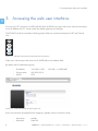
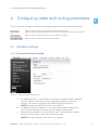
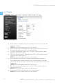
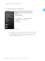
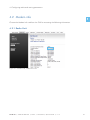
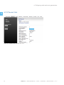
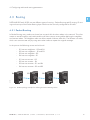
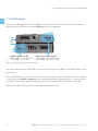
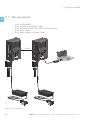
SATELLAR DIGITAL SYSTEM
PART I: 2DS/20DS
QUICK GUIDE VERSION 1.9
1
2DS/
20DS
QUICK GUIDE
WIRELESS WORLD – LOCAL SOLUTION
Copyright: 2014 SATEL Oy
No part of this document may be reproduced, transmitted or stored in a retrieval system in any form or by any
means without the prior written permission of SATEL Oy. This document is provided in confidence and must not be
distributed to third parties without the express permission of SATEL Oy.
Contents
Important notice
1
4
Introduction4
1.Hardware
5
1.1Connections
6
2.
Starting up the unit
7
3.
Accessing the web user interface
8
4.
Configuring radio and routing parameters
9
5.
4.1
Modem settings
4.1.1 Network Protocol Mode
4.1.2Radio
4.1.3 Serial Connector Configuration
4.1.4 Packet Mode Radio Access Control
9
9
10
11
12
4.2
Modem info
4.2.1 Radio Unit
4.2.2 Central Unit
13
13
14
4.3Routing
4.3.1 Packet Routing
4.3.2 IP Routing 4.3.3 Creating Packet Routing Tables
15
15
16
18
Testing environment
21
5.1
22
Test equipment
SATEL OY // SATELLAR MANUAL // PART I // 2DS/20DS // QUICK GUIDE // V. 1.9
3
1
Important notice
All rights to this manual are owned solely by
SATEL OY (referred to in this user guide as
SATEL). All rights reserved. The copying of this
manual (without written permission from the
owner) by printing, copying, recording or by any
other means, or the full or partial translation of
the manual to any other language, including all
programming languages, using any electrical,
mechanical, magnetic, optical, manual or other
methods or devices is forbidden.
SATEL reserves the right to change the technical
specifications or functions of its products, or to
discontinue the manufacture of any of its products or to discontinue the support of any of its
products, without any written announcement and
urges its customers to ensure that the information
at their disposal is valid.
SATEL software and programs are delivered ”as
is”. The manufacturer does not grant any kind of
warranty including guarantees on suitability and
applicability to a certain application. Under no
circumstances is the manufacturer or the developer of a program responsible for any possible
damages caused by the use of a program. The
names of the programs as well as all copyrights
relating to the programs are the sole property
of SATEL. Any transfer, licensing to a third party,
leasing, renting, transportation, copying, editing,
translating, modifying into another programming
language or reverse engineering for any intent is
forbidden without the written consent of SATEL.
SATEL PRODUCTS HAVE NOT BEEN
DESIGNED, INTENDED NOR INSPECTED TO
BE USED IN ANY LIFE SUPPORT - RELATED
DEVICE OR SYSTEM - RELATED FUNCTION
NOR AS A PART OF ANY OTHER CRITICAL SYSTEM AND ARE GRANTED NO FUNCTIONAL
WARRANTY IF THEY ARE USED IN ANY OF THE
APPLICATIONS MENTIONED.
Salo, Finland 2014
Introduction
The purpose of this document is to provide the
basic operating information and describe the
setup procedure for establishing IP communication link by using SATELLAR-2DS and -20DS
units.
It is recommended to get familiar with SATELLAR
Central Unit and SATELLAR Radio Unit user
guides before starting the actual configuration
process.
SATELLAR-2DS and -20DS units are wireless IP
routers. Therefore all SATELLARs should be configured to operate as the gateway for individual
subnets.
4
SATEL OY // SATELLAR MANUAL // PART I // 2DS/20DS // QUICK GUIDE // V. 1.9
1. Hardware
1. Hardware
1
SATELLAR-2DS and -20DS contains two modules – the Radio Unit (RU) and the Central Unit (CU),
which are stacked together.
1
2
RX
3
RX
TX
TX
RTS
RTS
CTS
CTS
TD
TD
RD
STAT
USB
RD
ETH
STAT
STAT
PWR
PWR
OK
RX
RX
TX
TX
RTS
RTS
CTS
USB
ETH
STAT
PWR
CTS
TD
RD
STAT
PWR
TD
USB
RD
ETH
STAT
STAT
PWR
PWR
OK
USB
ETH
STAT
PWR
SA00056
PWR
4
Figure 1.1 SATELLAR-2DS and SATELLAR-20DS types:
1. SATELLAR-2DS with display: Central unit (CU) with display and keypad + radio unit (RU) 1W
2. SATELLAR-2DS without display: Central unit (CU) without display and keypad + radio unit (RU) 1W
3. SATELLAR-20DS with display: Central unit (CU) with display and keypad + radio unit (RU) 10W
4. SATELLAR-20DS without display: Central unit (CU) without display and keypad + radio unit (RU) 10W
SATEL OY // SATELLAR MANUAL // PART I // 2DS/20DS // QUICK GUIDE // V. 1.9
5
1. Hardware
1.1 Connections
1
There are three sockets to be used:
–– Connect the antenna to the RF port (TNC female, 50 Ω). You can use
antenna cable, if found necessary. When testing the units over short radio
links (e.g. in the office), it is recommended to use attenuator (e.g. 20dB) in
RF port.
–– Connect the Power socket. Note the polarity of the power wires.
The operating voltage range is +9…+30 Vdc.
–– Connect the Ethernet cable. The SATELLAR supports the Auto-MDIX, so the
Ethernet cable can be direct or crossed.
SATELLAR-20DS
SATELLAR-2DS
CU
USB-A
_
USB-B
E
T
H
CU
USB-A
USB-B
_
+
RU
RU
9-30 VDC RS-485/RS-232
RF
E
T
H
+
9-30 VDC RS-485/RS-232
RF
RU
CU
Datainal
term ment
equip
RX
TX
RTS
CTS
TD
USB
RD
ETH
STAT
PWR
1.
3.
2.
r
Powely
supp VDC
9-30
15 W
+-
STAT
PWR
OK
min
2m
RF
9-30
VDC
ETH
able
5C
CAT-
SA00007
ble
RF caNC
T
with ale
m
Figure 1.2 Basic connections for configuration and IP communication (RF, Power, Ethernet)
6
SATEL OY // SATELLAR MANUAL // PART I // 2DS/20DS // QUICK GUIDE // V. 1.9
2. Starting up the unit
2. Starting up the unit
1
Radio boots up, when power socket is connected. Boot up time for SATELLAR-2DS and -20DS unit
is approx. 2 minutes. When the unit is in operation mode, the STAT and PWR LEDs are constantly lit.
The ETH and USB LEDs in the Central Unit are blinking if the connectors are not connected and are lit
when connected.
USB
ETH
RX
STAT
TX
RTS
CTS
TD
RD
STAT
PWR
ETH
STAT
PWR
OK
SA00031
PWR
USB
Figure 2.1 The LED indicators are located on the side of the unit
SATEL OY // SATELLAR MANUAL // PART I // 2DS/20DS // QUICK GUIDE // V. 1.9
7
3. Accessing the web user interface
1
3. Accessing the web user interface
Connect your PC computer to SATELLAR-2DS and -20DS Ethernet port and set the network card properties (IP address for PC, subnet mask and default gateway) accordingly.
The ETH LED will be lit constantly indicating proper Ethernet connection between the PC and Central
Unit.
USB
ETH
STAT
PWR
Figure 3.1 ETH LED indicates the proper Ethernet connection
Open your web browser and enter the IP (SATELLAR) to the address field.
By default the IP related settings are:
–– IP address: –– Subnet mask: –– DHCP:
192.168.1.2 (PC) 255.255.255.0
OFF
192.168.1.1 (SATELLAR)
Figure 3.2 SATELLAR WWW interface Login view
Enter the username and password for logging in (please note the character case):
–– Username: –– Password: 8
satellar
Satel123
SATEL OY // SATELLAR MANUAL // PART I // 2DS/20DS // QUICK GUIDE // V. 1.9
4. Configuring radio and routing parameters
4. Configuring radio and routing parameters
1
There is a specific procedure to follow for changing/modifying the settings and parameters.
Button is used for saving the modified parameter temporarily.
These changes will be listed/shown in the list of Uncommitted changes in the web GUI.
Button is used for making all temporary changes permanent.
Button will throw away the uncommitted changes.
4.1 Modem settings
4.1.1 Network Protocol Mode
Figure 4.1 Network Protocol Settings view
a) Set NetID parameter. This parameter should be considered a basic password,
which is used for determining that the messages belong to this specific
network. The maximum length of the NetID is eight (8) characters.
NOTE! Must be set equally in all units in the network.
b) Set Address (RMAC) parameter. This is used as the modem address and
source for generating the radio network IP address automatically.
c) Choose Protocol Mode from the pull-down menu. By default this is Packet
Routing, which is correct option for IP communication.
NOTE! Must be set equally in all units in the network.
SATEL OY // SATELLAR MANUAL // PART I // 2DS/20DS // QUICK GUIDE // V. 1.9
9
4. Configuring radio and routing parameters
1
4.1.2Radio
Figure 4.2 Radio settings view
a) Set TX Frequency and RX Frequency. Typically the local authorities give the
operating frequency.
NOTE! Must be set equally in all units in the network.
b) Set RF Output Power according to your radio license. Use pull-down menu
for selecting suitable power (100 mW steps available).
c) Set Signal Threshold. By default this is -114 dBm, which typically is good
option for basic system testing.
d) Set Over-the-Air Encryption. By default this is OFF, which typically is good
option for basic system testing.
NOTE! Must be set equally in all units in the network.
e) Set Forward Error Correction. This feature will add some characters to
the messages while transmitted and this way increases delays in the data
transmission. At the same time it improves the radio performance under weak
signal levels.
NOTE! Must be set equally in all units in the network
f) Set Channel Spacing. By default this is 25 kHz, which provides maximum
data rate over the air.
NOTE! Must be set equally in all units in the network.
g) Set Air Speed. Defines the data rate in the radio interface.
NOTE! Must be set equally in all units in the network.
10
SATEL OY // SATELLAR MANUAL // PART I // 2DS/20DS // QUICK GUIDE // V. 1.9
4. Configuring radio and routing parameters
4.1.3Serial Connector Configuration
1
Figure 4.3 Serial Connector Configuration
a) Check Radio Unit Port Assignment parameter. By default it is MCU UARTS
TO SATBUS WITH CAN, which is correct option for IP communication.
b) DTE Port Physical Communication Mode parameter can be left without
attention in TCP/IP communication.
SATEL OY // SATELLAR MANUAL // PART I // 2DS/20DS // QUICK GUIDE // V. 1.9
11
4. Configuring radio and routing parameters
1
4.1.4Packet Mode Radio Access Control
Figure 4.4 Packet Mode Radio Access Control view
a) Set Network Topology according to your application.
b) Retransmissions is by default ON, which means that the radio protocol
already follows the message flow and can notice, if some data packets are
lost and they need to be retransmitted. The number of retransmissions is one.
NOTE! Must be set equally in all units in the network.
c) Training Sequence Length values are Full and Half. Half means half size of
the original sequence length. This mode improves protocol efficiency and the
overall data speed becomes faster.
d) Set Back Off Counter value. This parameter defines the number of RTS time
slots the radio must wait before starting the transmission in case the radio
network is busy. The length of the RTS time slot depends on the radio parameters (e.g. 25 kHz/4FSK/FEC OFF it is
approx. 15 ms.) By default this value is 8, which typically is good option for basic system testing.
NOTE! Must be set equally in all units in the network.
12
SATEL OY // SATELLAR MANUAL // PART I // 2DS/20DS // QUICK GUIDE // V. 1.9
4. Configuring radio and routing parameters
4.2 Modem info
1
Choose the Modem Info -tab from the GUI for accessing the following information.
4.2.1Radio Unit
Figure 4.5 Modem Info / Radio Unit view
SATEL OY // SATELLAR MANUAL // PART I // 2DS/20DS // QUICK GUIDE // V. 1.9
13
4. Configuring radio and routing parameters
1
4.2.2Central Unit
Figure 4.6 Modem Info / Central Unit view
14
SATEL OY // SATELLAR MANUAL // PART I // 2DS/20DS // QUICK GUIDE // V. 1.9
4. Configuring radio and routing parameters
4.3 Routing
1
SATELLAR-2DS and -20DS use two different types of routing – Packet Routing and IP routing. IP routing works on top of the Packet Routing layer. Both must be correctly configured for IP traffic.
4.3.1Packet Routing
In Packet Routing every radio must know how to reach ALL the other radios in the network. This information is stored locally to each radio and they all have unique routing tables defining the neighbor
and remote radios. The Neighbor radio can be accessed via direct radio link. The Remote is a radio,
which can communicate only by using some other radio to repeat the original message.
In the picture the following routes can be found:
––
––
––
––
R1 has two neighbors – R2 and R4
R2 has two neighbors – R1 and R3
R3 has one neighbor – R2
R4 has one neighbor – R1
––
––
––
––
R1 has one remote – R3
R2 has one remote – R4
R3 has two remotes – R1 and R4
R4 has two remotes – R2 and R3
R4
R1
R2
R3
RX
RX
RX
TX
TX
TX
RTS
RTS
CTS
RD
PWR
RD
ETH
STAT
STAT
PWR
PWR
CTS
TD
USB
RD
ETH
STAT
STAT
PWR
PWR
TD
USB
RD
ETH
STAT
STAT
PWR
PWR
OK
USB
ETH
STAT
PWR
OK
OK
SA00027
OK
TX
RTS
CTS
TD
USB
RX
RTS
CTS
TD
STAT
Figure 4.7 Radio topology example for defining the Packet Routing tables
SATEL OY // SATELLAR MANUAL // PART I // 2DS/20DS // QUICK GUIDE // V. 1.9
15
4. Configuring radio and routing parameters
4.3.2IP Routing
There are two IP addresses in each SATELLAR unit; one for radio and one for ethernet. The ethernet
subnets of each SATELLAR must have different network IP addresses.
CU
RU
USB-A
USB-B
_
Radio
RF
SA00028
1
E Ethernet
T
H
+
9-30 VDC
radio subnet (tun 0)
Net IP addr: 10.10.32.0/19
R1 IP addr: 10.10.32.1
RS-485/RS-232
ethernet subnet (eth 0)
Net IP addr: 192.168.1.0/24
R1 IP addr: 192.168.1.100
Figure 4.8 SATELLARs two different subnets
The radio subnets of each SATELLAR must have the same network IP address. All radios belong to the
same subnet.
The network address (10.10.32.x) of the radio is defined automatically by SATELLAR. The unit address
(.x) is based on the RMAC addresses given under Network Protocol Mode tab (4.1.1 Network Protocol Mode). The base IP-address of radio subnet can be changed from Admin Tools, if necessary.
The user must define the IP routes for reaching the desired subnets.
16
SATEL OY // SATELLAR MANUAL // PART I // 2DS/20DS // QUICK GUIDE // V. 1.9
4. Configuring radio and routing parameters
CC Routes
192.168.2.0/24 via 10.10.32.2
192.168.3.0/24 via 10.10.32.3
192.168.4.0/24 via 10.10.32.4
Control centre
Site A Routes
192.168.1.0/24 via 10.10.32.1
192.168.3.0/24 via 10.10.32.3
192.168.4.0/24 via 10.10.32.4
1
Remote site A
3 MODBUS
TCP devices
R1
R2
RX
RX
TX
TX
RTS
RTS
CTS
CTS
TD
RD
STAT
PWR
TD
USB
RD
ETH
STAT
STAT
PWR
PWR
USB
ETH
STAT
PWR
OK
OK
10.10.32.0/19
RX
RX
TX
TX
RTS
RTS
CTS
CTS
TD
RD
STAT
PWR
TD
USB
RD
ETH
STAT
STAT
PWR
PWR
USB
ETH
STAT
PWR
OK
OK
R4
SA00029
Remote site C
sensor logic
with simple http
server
Site C routes
192.168.1.0/24 via 10.10.32.1
192.168.2.0/24 via 10.10.32.2
192.168.3.0/24 via 10.10.32.3
R3
Remote site B
2 MODBUS
TCP devices
Site B routes
192.168.1.0/24 via 10.10.32.1
192.168.2.0/24 via 10.10.32.2
192.168.4.0/24 via 10.10.32.4
Figure 4.9 Example of the IP routes for a SATELLAR network
SATEL OY // SATELLAR MANUAL // PART I // 2DS/20DS // QUICK GUIDE // V. 1.9
17
4. Configuring radio and routing parameters
1
4.3.3Routing settings
Access the Routing tab for entering the Packet Routes, IP address and IP Routes accordingly.
–– Neighbor: The RMAC of a direct neighbor.
–– Remotes: RMACs of modems found behind of that neighbor.
Set RMAC addresses of neighbor and remote radio units accordingly.
Click Add Routing Data button for applying the new packet routes.
Figure 4.10Packet Routing Tables view
18
SATEL OY // SATELLAR MANUAL // PART I // 2DS/20DS // QUICK GUIDE // V. 1.9
4. Configuring radio and routing parameters
1
Figure 4.11IP view
Set eth0 IP Address according to your networks. Subnet mask should be given in /nn format
(e.g. /24 stands for 255.255.255.0).
NOTE! Other parameters can typically left as they are in basic testing procedures.
SATEL OY // SATELLAR MANUAL // PART I // 2DS/20DS // QUICK GUIDE // V. 1.9
19
4. Configuring radio and routing parameters
1
Figure 4.12IP Routes view
Add IP route to each subnet the unit should communicate to. The format is IP address/Subnet mask
Gateway (e.g. 192.168.2.0/24 10.10.32.2).
Add New Route button applies new routes.
Editing existing route can be done by typing in the necessary changes, putting the tick mark to the
check box and clicking Apply changes button.
Deleting existing route can be done by putting the tick mark to the check box and clicking Delete
Selected button.
Commit the changes for making them permanent to the particular unit.
Complete the same procedure to all radio modems in the network and use e.g. ping command for
testing the TCP/IP communication.
20
SATEL OY // SATELLAR MANUAL // PART I // 2DS/20DS // QUICK GUIDE // V. 1.9
5. Testing environment
5. Testing environment
1
When testing the radio performance on the desk, the signal strength may become so high that the
receiver gets blocked. The critical value with 16-FSK modulation (allowing the maximum baud rate
over the air) is approx. -20 dBm.
This level can be (typically) reached by using:
––
––
––
––
0 dBi antennas
20 dB attenuator in both ends of the link
100 mW transmission power
> 50 cm distance between radio units.
Unless attenuators are available, the distance between radio units should be increased to some meters.
SATEL OY // SATELLAR MANUAL // PART I // 2DS/20DS // QUICK GUIDE // V. 1.9
21
5. Testing environment
5.1 Test equipment
––
––
––
––
––
2 pcs, SATELLAR-2DS
2 pcs, Antennas (e.g. MiniFlex, 0 dBi)
2 pcs, Attenuator (20 dB / 10W, TNCm/TNCf connectors)
2 pcs, Power cables
2 pcs, Power supplies (9...30 Vdc / 30W)
RX
RX
TX
> 50 cm
RTS
CTS
TD
RD
STAT
PWR
TX
RTS
CTS
TD
USB
RD
ETH
STAT
STAT
PWR
PWR
OK
USB
ETH
STAT
PWR
OK
SA000030
1
Figure 5.1 Test equipment
22
SATEL OY // SATELLAR MANUAL // PART I // 2DS/20DS // QUICK GUIDE // V. 1.9
SATEL Oy
Meriniitynkatu 17, P.O.Box 142
FI-24101 Salo, Finland
Tel. +358 2 777 7800
[email protected]
www.satel.com
WIRELESS WORLD – LOCAL SOLUTION