1
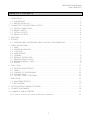
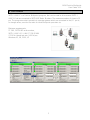
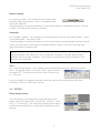
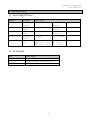
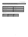
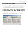
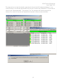
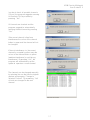
USER GUIDE
M2M
Point – to – Multipoint
M2M Point-to-Multipoint
User Guide V2.0
TABLE OF CONTENTS
1
INSTALLATION ........................................................................................................................... 3
1.1 SUB-STATIONS..................................................................................................................... 3
1.2 MASTER STATION (PC) ......................................................................................................... 3
2
CONNECTING THE INPUTS AND OUTPUTS ............................................................................... 4
2.1
2.2
2.3
2.4
DIGITAL CONNECTIONS ..................................................................................................... 4
ANALOG INPUTS ................................................................................................................. 4
DIGITAL OUTPUTS ............................................................................................................... 4
ANALOG OUTPUTS.............................................................................................................. 4
3
PROGRAM ................................................................................................................................. 5
4
SETTINGS................................................................................................................................... 6
4.1 SATELLINE RADIO MODEM AND SATEL I-LINK 100 CONFIGURATIONS ................................ 6
5
USING THE PROGRAM ............................................................................................................... 7
5.1
5.2
5.3
5.4
5.5
5.6
5.7
5.8
5.9
6
SAVE / LOAD............................................................................................................................ 11
6.1
6.2
6.3
6.4
6.5
7
START .................................................................................................................................. 7
OPERATION WINDOW ........................................................................................................ 7
COM PORT.......................................................................................................................... 7
SLAVE ADDRESS ................................................................................................................... 7
GENERAL ............................................................................................................................. 8
SENDING DIGITAL DATA ..................................................................................................... 8
SENDING ANALOG DATA .................................................................................................... 8
RECEIVING ANALOG DATA ................................................................................................. 8
EDITING .............................................................................................................................. 9
SELECTED SLAVE SETTINGS ................................................................................................ 11
SAVING.............................................................................................................................. 11
LOADING OF THE NEW SLAVE........................................................................................... 11
CLOSING SLAVE ................................................................................................................ 11
CLOSING I-LINK PC PROGRAM.......................................................................................... 11
INDICATORS ............................................................................................................................ 12
7.1 ADJUSTABLE SETTINGS ...................................................................................................... 12
7.2 BOTTOM BAR .................................................................................................................... 12
8
FACTORY SETTINGS AND ACCESSORIES.................................................................................. 13
9
CONNECTION EXAMPLE.......................................................................................................... 14
10 CHANNEL CHANGE GENERAL................................................................................................ 15
10.1 HOW TO CHANGE THE CHANNEL IN MULTIPOINT OPERATION ...................................................... 15
1
M2M Point-to-Multipoint
User Guide V2.0
GENERAL
This installation manual provides you in brief with all the essential information you need to get
your cordless SATEL M2M Multipoint package in working condition. The wireless SATELLINE
radio modem enables the devices' mutual communication. SATELLINE-1870 radio modems
operate on license-free radio frequencies and can therefore be taken into use immediately
without separate permission from the authorities. All of the settings etc. needed for a connection
have already been adjusted so all you have to do is the final hook-up.
The Multipoint Package
This package enables you to wirelessly control and monitor the operations of two sub stations
with one master station. The equipment makes it possible to send and receive 4 status signals
(switch or other digital status), or 2 analog signals/measurement data. The measuring sensors
for analog data should be designed for 4....20 mA current loop data. All changes in the substation input (DIGITAL or ANALOG INPUT) are transmitted to the Master station display as
visible output (DIGITAL or ANALOG OUTPUT). Correspondingly, separate controlling
is possible directly from the master station to the sub-stations.
Contents of the M2M Package:
Number in the picture:
3 pcs of radio modems with antennas
(1and 2)
2 pcs of I-LINK 100 I/O- converters
(3)
3 pcs of interface cables
(4)
3 pcs of power supplies
(5)
1pc of I-LINK PC Multipoint programme
1pc installation instruction user guide for the I-LINK 100
2
M2M Point-to-Multipoint
User Guide V2.0
1 INSTALLATION
The installation part consists of the installation and how to make the wiring (paragraph 2
CONNECTING THE INPUTS AND OUTPUTS). The use of the program is explained in the
paragraph 5 USING THE PROGRAM
General
Choose the places for installation where the products may be easily mounted. If at all possible,
choose a place where there is nothing to obstruct (walls, etc.) the transmission of radio
signals 'between' the antennas of the main drive and the sub-stations.
1.1 SUB-STATIONS
1. Connect antenna (1) to the radio modem (2).
2. Connect the interface cable (4) to the radio modem
and the I-LINK 100 (3).
3. Connect the power supply (5) to the I-LINK 100 screw
couplings +9 … +30 Vdc. Connect the power supply's black
wire to the negative pole (-) and the red wire to the positive pole (+).
Make the connections to the other equipment as well.
The sub-stations are now installed..
1.2 MASTER STATION (PC)
1. Connect the antenna (2) to the radio modem (1).
2. Connect the interface cable (4) to the radio modem
and the PC's (3) COM port.
3. Connect the power supply (5) to the wall socket.
The master station is now installed.
3
M2M Point-to-Multipoint
User Guide V2.0
2 CONNECTING THE INPUTS AND OUTPUTS
Once you have installed the M2M package, all you need to do is just connect the actual inputs
and outputs.
2.1 DIGITAL CONNECTIONS
Connect switch status or other data to any input of
the sub-station (DIGITAL INPUT), so that you get
a status change in the input, i.e. +12 V / 24 V 'ON
or OFF'. You can take the + (plus) Voltage from
the + - screw of the I-LINK 100, or from the separate
+ - output next to it.
Digital Inputs Analog Inputs
2.2 ANALOG INPUTS
Analog sensors and gauges should be connected to their own + and - inputs and outputs.
Notice that the sensors need their own supply voltage, mentioned separately in connection with
the delivery of the sensor.
Choose the analog sensor transmission sequence with the I-LINK PC programme.
2.3 DIGITAL OUTPUTS
Changes in the sub-station outputs are done by using commands on the master station display.
When the main station input is pressed, the respective sub-station output relay contacts changes
accordingly. The relay contacts are normally open. Each contact can be connected
independently, and can perform the desired function by using them to connect plus or minus
Voltage to the desired device. The contacts can also be used to control a 230 Volt device at
maximum of 2 Amperes.
2.4 ANALOG OUTPUTS
Connect the device you want to control
to the output.
Driving voltage
Digital outputs
Analog outputs
To the
controlled
device
When all outputs are connected, mount
the power supply to the mains voltage.
For more information concerning the
functions of the I-LINK 100, see the
I-LINK 100 user manual in the M2M
package.
4
M2M Point-to-Multipoint
User Guide V2.0
3 PROGRAM
SATEL I-LINK PC is a Point-to-Multipoint program, that can be used to drive several SATEL ILINK 100 slaves connected to SATELLINE Radio Modems. The maximum number of slaves is 16
pcs. The program makes it possible to operate systems which are connected to the I/O -ports,
to change values, monitor the radio link and Multipoint operation etc.
Minimum requirements:
PC 286, SATELLINE radio modem,
SATEL I-LINK 100, I-LINK PC PROGRAM
COM Port baud rate min. 9600 b/sec.
Windows 95, 98, 2000, XP
5
M2M Point-to-Multipoint
User Guide V2.0
4 SETTINGS
NOTE!
If you are using SATEL M2M- package, all setings in page are already done and you may
continue from point 4 onwards.
4.1 SATELLINE RADIO MODEM AND SATEL I-LINK 100 CONFIGURATIONS
BAUD RATE
Set the baud rate of the SATELLINE radio modem. Check that the other parameters are “N, 8, 1”
(8 data bits, no parity, 1 stop bit).
Set the baud rate of the SATEL I-LINK100 by using the BAUD DIP -switches.
00=2.4, 10=4.8, 01=9.6, 11=19.2 (check that the SATELLINE radio modems have the same
settings).
PROTOCOL
Set the SATEL I-LINK 100 PRTCL switch to the Multipoint position, P-to-MP.
ADDRESS
Set personal addresses to all SATEL I-LINK 100 slaves by using the ADDRESS DIP -switches.
CONNECTIONS
Before connecting the device to a power supply, first connect all inputs and outputs. More
information about connections can be found at the end of the manual.
6
M2M Point-to-Multipoint
User Guide V2.0
5 USING THE PROGRAM
5.1 START
Instal the attached CD to your PC and open the SATEL I-LINK PC program by double clicking
the
-icon.
5.2 OPERATION WINDOW
Open a new operation window from the toolbar list by clicking the
-button on the upper left
corner, or Open by clicking on the File Menu, opening "New Slave". Open your own window to
all slaves. Note that the maximum number of slaves in this program is 16. Arrange the display
by using the Windows Menu or the
-buttons.
5.3 COM PORT
Open the COM- port from the toolbar list by clicking
“Master Config” and select “Open ComPort”. Set the
same parameters as you have set for the SATELLINE
radio modem and SATEL I-LINK 100, then press OK.
If there are no COM -port settings, the program will automatically ask for them.
5.4 SLAVE ADDRESS
When the new slave is opened, the program will automatically set the address
for it. To make manual adjustments, click anywhere on the empty table using
the right mouse button, and select “Set slave address”. Insert the new address,
and then press OK.
NOTE!
THE BASIC SETTINGS HAVE NOW BEEN ESTABLISHED AND THE SATEL I-LINK PC IS
READY TO SEND AND RECEIVE INFORMATION.
7
M2M Point-to-Multipoint
User Guide V2.0
5.5 GENERAL
Changes in the sub-station outputs are done by using commands on the master station display.
Changes in the sub-station inputs are shown respectively on the master station display.
When the sub-station Inputs I1…I4 level changes from 0 to +12 … +24 Vdc or vice versa, the
indicator in the master station display changes respectively.
When the main station’ digital output is pressed, the respective sub-station output relay contacts
changes accordingly. The relay contacts are normally open. Each contact can be connected
independently, and can perform the desired function by using them to connect plus or minus
Voltage to the desired device. The contacts can also be used to control a +12 … +24 Vdc or
230 Vac devices at maximum of 2 Amperes.
Changing of the analog level in the sub station analog output is done by moving the “analog”
cursor in the display.
Analog information coming from the sub station is shown in the display as 0…100 % value
bar.
5.6 SENDING DIGITAL DATA
To change the slave's digital value, click the grey “Digital
Output” circle dot. During the transmission the dot is
yellow. When the transmission is done, the circle will
change to green. If the transmission fails, the “Operation”
signal will turn red.
5.7 SENDING ANALOG DATA
Move the “Analog Output Cursor” or change the
number at the side. Press “Send Analog Data” and
the levels will be sent to the Slave's “Analog Output”.
If the transmission fails, the “Operation” signal will turn red. Note that “Analog Output” can
only be sent by pressing “Send Analog Data”.
5.8 RECEIVING ANALOG DATA
There are three different modes to receive data; manual,
automatic or time. The settings can be done separately for
each window.
8
M2M Point-to-Multipoint
User Guide V2.0
Manual update
For manual update – click anywhere on the empty table
using the right mouse button - select “Set update mode” ,
and press “Manual”.
Using this setting, the slave information for the chosen window is updated only when “Manual
Update” circle-dot in this window is pressed.
Automatic
For automatic update – click anywhere on the empty table using the right mouse button - select
“Set update mode”, and press “Auto”.
Using this setting, the slave information for the chosen window is updated with maximum speed.
If only one slave has an auto setting, the update speed is about 1 second. Every new auto
setting increases the update time.
NOTE!
Use this setting for the Slaves only, if it is absolutely necessary. The Auto setting makes
maximal use of the radio frequency. The continuous reservation of radio frequency is not
generally recommended.
Time
For a Time based update – click anywhere on the empty table using the right mouse button select “Set update mode”, and press “Time”, select the time
and press SET. The time interval can be from 5 seconds up
to …24 hours.
Using this setting, the update information from the slave to the chosen window will be in
accordance with the “Select time” setting.
5.9 EDITING
Slave window layout
Click anywhere on the empty table using the right mouse
button, select "Set layout style" and set it for “Normal”, “Input
only” or “Output only”. The inputs and outputs can be seen in
the window simultaneously or separately, depending on the
settings.
9
M2M Point-to-Multipoint
User Guide V2.0
Changing the Slave name
Click anywhere on the empty table using the right mouse button –
select "Set Name" – type the new name and press OK.
Changing Input / Output names
Click on the right mouse button on top of the text that you want to edit,
make the changes and press ok.
Unit Conversion
Normally the analog input and output unit is shown as % and the scaling is from 0 to
100.
The unit can be changed to be any other unit maximum five characters. The value can also be
re-scaled by setting the minimum and maximum values that the sensor and device applies.
Click anywhere on the empty table of the selected slave using the right mouse button, select "Set
Unit Conversion” and click. Set new values and re-scale the min and max value. Execute the
function by clicking Use.
10
M2M Point-to-Multipoint
User Guide V2.0
6 SAVE / LOAD
6.1 SELECTED SLAVE SETTINGS
Click anywhere on the empty table of the selected slave
using the right mouse button, select "Save Settings" and press OK.
6.2 SAVING
Select FILE - "Save All", select path and save. This function will save all slaves using their current
names.
6.3 LOADING OF THE NEW SLAVE
Select FILE - "Load Slave(s)" and open the file. Because the
information of the now loaded slave may be different from
what it currently is, the program asks “Do you want to
update slave(s)? Select Yes / No".
6.4 CLOSING SLAVE
Click anywhere on the empty table of the
selected slave using the right mouse
button and click "Close".
In the event that the program has not be
Saved, the program asks “Are you sure
you want to close slave? Select Yes / No."
6.5 CLOSING I-LINK PC PROGRAM
Select FILE – EXIT. If any of the Slaves are still open, the
program asks “Are you sure?” Select Yes /No.
11
M2M Point-to-Multipoint
User Guide V2.0
7 INDICATORS
7.1 ADJUSTABLE SETTINGS
OBJECT
Operation
Digital Output
Digital Input
Analog Output
Analog Input
ACTION
Status of the
operation
State of the
outputs
State of the
inputs
The output
level in %
The input level
in %
OUTCOME
Green= OK
0 = 4 mA
Yellow =
Running
Yellow =
Running
Yellow =
Running
100 = 20 mA
Yellow = 0 ... 25 %
Green = 25 ... 100 %
Red = 100 ... 125 %
0 ... 4 mA
4 ... 20 mA
20 ... 25 mA
Green= OK
Green= OK
7.2 BOTTOM BAR
TEXT
Manual tai Auto
”00:00:00”
Address:
FUNCTION
Shows the analog input update selection
Shows the analog input update time
Shows the address of the slave
12
Red = Fail
Grey = OFF
Grey = OFF
M2M Point-to-Multipoint
User Guide V2.0
8 FACTORY SETTINGS and ACCESSORIES
The I-LINK100 I/O-converter is shipped with the following default:
FIXED SETTINGS DEFINED AT THE TIME OF ORDER
PRTCL, protocol -switch
1 = P-to-MP
ADDRESS
1000000 and 0100000
BAUD
01 = 9600 bps
DE 3, Alarm delay
0 = no delay
SM 4, Safe Mode
0 = Safe Mode OFF
HS 5, Handshaking
0 = CTS ON
TIME, Analogue transmission interval
000 =120 minutes
Interface cables
DEVICE
PC
I-LINK 100
RADIO MODEM
SATELLINE-1870
SATELLINE-1870
CABLE
CRS-18F
CRS-18IF
13
M2M Point-to-Multipoint
User Guide V2.0
9 CONNECTION EXAMPLE
14
M2M Point-to-Multipoint
User Guide V2.0
10
CHANNEL CHANGE GENERAL
The radio modems of the M2M-package operate on the European license free frequency band.
This band has several different channels. Sometimes it may happen that few systems use the
same channel. If this occurs, the system stability may change and behave in an uncertain
manner. However, if this happens, it is possible to change the radio modems to another
channel.
The standard M2M sale s package is pre-set to a specific channel and changes are
not needed in order to start the normal operation. The changes are needed only,
if the system doesn’t work properl y.
10.1 How to change the channel in Multipoint operation
In multipoint operation the channels can be changed using the I-LINK PC Program;
by tabbing the Window and selecting the Channel Selector.
Channel selector
15
M2M Point-to-Multipoint
User Guide V2.0
The program has not yet checked the operational channel and following text displays “Your
current channel is not known and therefore all the scan controls are unavailable. Do you want to
check it now? (Recommended)”. By pressing “Yes” the program will find the operational
channel. As a result of the scan the operational channel is shown at the bottom bar.
16
M2M Point-to-Multipoint
User Guide V2.0
In order to check all possible channels
(10 pcs), the program suggests scanning
all channels. This is possible by
pressing, “Yes”.
All channels are checked and the
program suggests to automatically
selecting the best channel by pressing
“Yes”.
If the current channel is free from
interferences the colour of the channel
button is green and the channel will not
be changed.
If there is interference i.e. the current
channel is occupied by other users the
colour of the channel button is yellow
(medium interference) or red (strong
interference). By pressing “Yes”, the
program will automatically set the
system to operate on a new channel.
The channels can be changed manually
by selecting the one that has the highest
number and pressing “Change to
Selected Channel”. By answering, “Yes”
all units are changed to the new
channel.
17
M2M Point-to-Multipoint
User Guide V2.0
18
SATEL OY
Meriniitynkatu 17, P.O. Box 142
24101 Salo, FINLAND
Tel: +358 2 777 7800
Fax: +358 2 777 7810
E-mail [email protected]
www.satel.fi