1
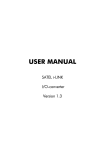
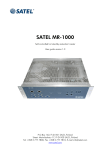
M2M i-LINK
POINT-TO-MULTIPOINT
INSTALLATION INSTRUCTIONS
M2M i-LINK, MP
User Guide, EN, V1.2
1 TABLE OF CONTENTS
1
TABLE OF CONTENTS ................................................................................................................................. 2
2
GENERAL .................................................................................................................................................... 3
3
INSTALLATION ............................................................................................................................................ 4
3.1 SUB-STATIONS ............................................................................................................................. 4
3.2 MAIN STATION (PC)...................................................................................................................... 4
4
CONNECTING THE INPUTS AND OUTPUTS ................................................................................................ 5
4.1 INPUTS OF THE SUB-STATION .............................................................................................................. 5
4.2 PULSE INPUT ................................................................................................................................... 5
4.3 DIGITAL OUTPUTS ........................................................................................................................ 5
5
PROGRAM .................................................................................................................................................. 6
6
SETTINGS ................................................................................................................................................... 7
7
USING THE PROGRAM................................................................................................................................ 8
7.1 START .......................................................................................................................................... 8
7.2 OPERATION WINDOW ....................................................................................................................... 8
7.3 COM- PORT .................................................................................................................................. 8
7.4 SUB-STATION ADDRESS ...................................................................................................................... 8
7.5 GENERAL ..................................................................................................................................... 9
7.6 SENDING DIGITAL DATA ..................................................................................................................... 9
7.7 RECEIVING DIGITAL DATA ................................................................................................................... 9
7.7.1 Manual (default) ........................................................................................................................... 9
7.7.2 Auto .......................................................................................................................................... 10
7.7.3 Time .......................................................................................................................................... 10
7.8 PULSES (COUNTER INPUT 1, TICK) UPDATING. TICKS PER UNIT. UNIT. ........................................................ 10
7.8.1 Additive count is chosen .............................................................................................................. 10
7.8.2 Additive count is NOT chosen ...................................................................................................... 10
7.8.3 Pulse divider, Ticks per Unit: ........................................................................................................ 11
7.8.4 Pulse unit, (Tick). ......................................................................................................................... 11
7.9 EDIT FUNCTIONS ........................................................................................................................... 11
7.9.1 Set layout style ............................................................................................................................ 11
7.9.2 Set name .................................................................................................................................... 11
7.9.3 Input/Output names .................................................................................................................... 11
7.9.4 Save sub-station .......................................................................................................................... 11
7.9.5 Save all sub-stations .................................................................................................................... 11
7.9.6 Load sub-station ......................................................................................................................... 11
7.9.7 Close sub-station ........................................................................................................................ 12
7.9.8 Exit ............................................................................................................................................ 12
8
CHANNEL CHANGE.................................................................................................................................. 13
8.1.1
9
Selecting a new channel .............................................................................................................. 13
INDICATORS............................................................................................................................................. 15
9.1 FUNCTIONS AND OUTCOMES .................................................................................................. 15
9.2 BOTTOM BAR ............................................................................................................................ 15
10
FACTORY SETTINGS ................................................................................................................................ 16
11
CONNECTION EXAMPLES ....................................................................................................................... 17
2
M2M i-LINK, MP
User Guide, EN, V1.2
2 GENERAL
Dear Customer,
This installation manual provides you in brief with all the essential information you need to
get your cordless SATEL M2M i-LINK Multipoint package in working condition. The wireless
SATELLINE radio modem enables the devices' mutual communication. SATELLINE radio
modems operate on license-free radio frequencies and can therefore be taken into use
immediately without separate permission from the authorities. All of the settings etc. needed
for a connection have already been adjusted so all you have to do is the final hook-up.
The M2M Multipoint Package
This package enables you to wirelessly control and monitor the operations of two sub stations
with one main station. The equipment makes it possible to send and receive 2 status signals
(switch or other digital status), collect pulse information. All changes in the sub-station digital
or pulse are transmitted to the main station display as visible output. Correspondingly,
separate controlling is possible directly from the main station to the sub-stations.
Contents of the M2M Package:
Number in the picture:
3 pcs of radio modems with antennas
(1and 2)
2 pcs of i-LINK I/O-converters
(3)
3 pcs of power supplies
(4)
3 pcs of antenna installation plates
(5)
3 pcs of antenna cables
(6)
1 pc of MINI-LINK PC Multipoint program
1 pc of installation instructions
3
M2M i-LINK, MP
User Guide, EN, V1.2
3 INSTALLATION
The installation part consists of the installation and how to make the wiring (CONNECTING THE
INPUTS AND OUTPUTS). The use of the program is explained in the paragraph USING THE
PROGRAM.
Choose the places for installations where the products may be easily mounted. If at all possible,
choose a place where there is nothing to obstruct (walls, etc.) the transmission of radio signals
'between' the devices' antennas.
3.1
1.
2.
3.
4.
SUB-STATIONS
Connect the antenna cable (6) to Installation plate (5).
Connect the antenna (1) to the installation plate.
Connect the antenna cable to the radio modem (2).
Connect the power supply (4) to the i-LINK screw couplings 9-30VDC. Connect the power
supply's black wire to the negative pole (-) and the red wire to the positive pole (+).
5. Connect the i-LINK to the radio modem so that it is locked.
Make these connections to the other equipment(s) as well.
Note! The antennas can also be connected directly to the radio modems
without the cable and installation plate, if needed.
The sub-stations are now installed.
3.2
MAIN STATION (PC)
1. Connect the antenna cable (6) to the installation plate (5).
2. Connect the antenna (1) to the installation plate.
3. Connect the antenna cable to the Radio Modem (2).
4. Connect the interface cable (7) to the radio modem (so that it is locked) and the PC's COM
port.
5. Connect the power supply (4) to the wall socket.
The main station is now installed.
Note! The antennas can also be connected directly to the radio modems
without the cable and installation plate, if needed.
4
M2M i-LINK, MP
User Guide, EN, V1.2
4 CONNECTING THE INPUTS AND OUTPUTS
Once you have installed the M2M package, all you need to do is just connect the actual inputs
and outputs.
4.1
4.2
INPUTS OF THE SUB-STATION
Connect switch status or other data to D1 or D2 input of the
sub-station, so that you get a status change in the input, i.e.
+12 V / 24 V 'ON or OFF'. You can take the + (plus)
Voltage from the + -screw of the i-LINK, or from the
separate + -output next to it.
PULSE INPUT
Input pulses are connected to the P (Pulse Input) screw.
The maximum frequency is 10 kHz. Reading occurs at the
pulse edge. The function can be used by the MINI-LINK PC
program.
D1, D2 = Input
4.3
Outputs
DIGITAL OUTPUTS
Changes in the sub-station outputs are done by using commands on the main station
display. When the main station input is pressed, the respective sub-station output relay
contacts changes accordingly. The relay contacts are normally open. Each contact can be
connected independently, and can perform the desired function by using them to connect
plus or minus Voltage to the desired device. The contacts can also be used to control a 1224 Volt device at maximum of 1 Amperes.
When all inputs and outputs are connected, mount the power supply to the
mains voltage. For more information concerning the functions of the i-LINK,
see the user manual in the M2M package.
5
M2M i-LINK, MP
User Guide, EN, V1.2
5 PROGRAM
SATEL MINI-LINK PC is a Point-to-Multipoint program, that can be used to drive several
SATEL i-LINK sub-stations connected to SATELLINE radio modems. The maximum number of substations is 15 pcs. The program makes it possible to operate systems which are connected to the
I/O -ports, to change values, monitor the radio link and Multipoint operation etc.
Minimum requirements:
PC 286, SATELLINE radio modem,
SATEL i-LINK,
MINI-LINK PC program,
COM Port baud rate min. 9600 b/sec.
Windows 95, 98, 2000, XP
EXAMPLE
ESIMERKKI
6
M2M i-LINK, MP
User Guide, EN, V1.2
6 SETTINGS
NOTE!
If you are using SATEL M2M i-LINK package, all settings in this page are already done and
you may continue from the next page.
SETTINGS OF THE SATELLINE RADIO MODEM AND i-LINK:
o The radio modem PORT settings are: 9600 kbps, "N-8-1".
o M/P-switch is in M-position.
o Before connecting the device to a power supply, connect first all inputs and outputs that are
to be used.
o Set addresses to both units, for example (1)100 0000 and (1)010 0000. The first (1) is the
Multipoint switch that must be in set to "1"-position.
o When both units have these basic settings the supply voltage can be connected.
7
M2M i-LINK, MP
User Guide, EN, V1.2
7 USING THE PROGRAM
7.1
START
7.2
OPERATION WINDOW
Instal the attached CD to your PC and open the SATEL MINI-LINK PC program by double
clicking the
Satel_Mini-Link_PC_v.... -icon.
Open a new operation window from the toolbar list by clicking the
-button on the upper left
corner, or Open by clicking on the File Menu, opening "New Slave". Open your own window to
all sub-stations. Note that the maximum number of sub-stations in this program is 16. Arrange
the display by using the Windows Menu or the
7.3
COM- PORT
7.4
SUB-STATION ADDRESS
-buttons.
Open the COM- port from the toolbar list by clicking
“Master Config” and select “Open ComPort”. Set the
same parameters as you have set for the SATELLINE
radio modem and SATEL i-LINK, then press OK.
If there are no COM -port settings, the program will automatically ask for them.
When the new sub-station is opened, the program will automatically set the
address for it. To make manual adjustments, click anywhere on the empty
table using the right mouse button, and select “Set slave address”. Insert the
new address, and then press OK.
THE BASIC SETTINGS HAVE NOW BEEN ESTABLISHED AND THE SATEL
MINI-LINK PC IS READY TO SEND AND RECEIVE INFORMATION.
8
M2M i-LINK, MP
User Guide, EN, V1.2
7.5
GENERAL
Changes in the sub-station outputs are done by using commands on the main station display.
Changes in the sub-station inputs are shown respectively on the main station display.
When the sub-station Inputs D1…D2 level changes from 0 to +12 … +24 Vdc or vice versa, the
indicator in the main station display changes respectively. Grey represents OFF- and green ONstate.
When the main station’ digital output is pressed, the respective sub-station output relay contacts
changes accordingly. The relay contacts are normally open. Each contact can be connected
independently, and can perform the desired function by using them to connect plus or minus
Voltage to the desired device. The contacts can also be used to control +12 … +24 Vdc devices
at maximum of 1 Amperes.
The Pulse information (for example electric meter) is seen in the window in the "Counter Input"
(Tick) box.
7.6
SENDING DIGITAL DATA
7.7
RECEIVING DIGITAL DATA
To change the sub-station's digital value, click the grey “Digital
Output” circle dot. During the transmission the dot is yellow.
When the transmission is done (in about 1 sec), the circle will
change to green. If the transmission fails, the “Operation”
signal will turn red.
The digital inputs and pulse information from the sub-stations will be updated to the main
station window when the main station updates occurs. There are three different modes to update
the data; manual, auto or time. The settings can be done separately for each window (substation).
7.7.1 Manual (default)
For manual update – click anywhere on the empty table using
the right mouse button - select “Set update mode”, and press
“Manual”. Using this setting, the sub-station information for the
chosen window is updated only when “Manual Update” circledot in this window is pressed.
9
M2M i-LINK, MP
User Guide, EN, V1.2
7.7.2 Auto
For automatic update – click anywhere on the empty table using the right mouse button - select
“Set update mode”, and press “Auto”.
Using this setting, the sub-station information for the chosen window is updated with maximum
speed. If only one sub-station has an auto setting, the update speed is about 1 second. Every
new auto setting increases the update time.
NOTE!
Use this setting for the sub-stations o nly, if it is absolutely necessary. The
Auto setting makes maximal use of the radio frequency. The continuous
reservation of radio frequency is not generally recommended.
7.7.3 Time
Using this setting, the update information from the sub-station to the chosen window will be in
accordance with the “Select time” setting.
For a Time based update – click anywhere on the empty
table using the right mouse button - select “Set update
mode”, and press “Time”, select the time and press SET.
The time interval can be from 5 seconds up to …24
hours.
7.8
PULSES (COUNTER INPUT 1, TICK)
UPDATING. TICKS PER UNIT. UNIT.
The latest pulse information will be shown in the window
when the sub-station is updated (manual, auto or time).
Pulse reading type can be "additive" or "once".
Additive
count
7.8.1 Additive count is chosen
When
is chosen, the new counter value is added to the previous value at every
update. (Example: Current value is 20. Sub-station is updated when 3 new pulses has been
received. New counter value will be 20+3=23).
7.8.2 Additive count is NOT chosen
When
is not chosen, the new counter value replaces the previous value.
(Example: Current value is 20. Sub-station is updated whe 3 new pulses has been received. New
counter value will be 3).
NOTE! If the pulse reading occurs for example once a month, the update type shouls be Manual.
When Manual update is pressed a new reading is shown and the previous one is reset.
10
M2M i-LINK, MP
User Guide, EN, V1.2
7.8.3 Pulse divider, Ticks per Unit:
When
is greater than 1, the incoming pulses are multiplied with this number. When
is less than 1 (for example 0,1), the incoming pulses are divided with this number.
7.8.4 Pulse unit, (Tick).
The default Unit "Tick" is replaced by typing new text.
7.9
EDIT FUNCTIONS
7.9.1 Set layout style
The inputs and outputs can be seen in the window simultaneously or
separately, depending on the settings. Click anywhere on the empty
grey area of the sub-station window using the right mouse button,
select "Set layout style" and set it for “Normal”, “Input only” or
“Output only”.
7.9.2 Set name
Select "Set Name" – type a new name and press OK.
7.9.3 Input/Output names
Click normally at the name that you want to change and
it opens for editing. Make the changes and press OK.
7.9.4 Save sub-station
Saves the current Sub-station to the PC. Click anywhere on the empty grey
area of the sub-station window using the right mouse button, select “Save
Settings”, browse for the file path and press OK.
7.9.5 Save all sub-stations
Select FILE - "Save All", select path and save. This function will save all
sub-stations using their current names.
7.9.6 Load sub-station
Select FILE - "Load Slave(s)" and open the file. Because the information of the now loaded substation may be different from what it currently is, the program asks “Do you want to update
slave(s)? Select Yes / No".
11
M2M i-LINK, MP
User Guide, EN, V1.2
7.9.7 Close sub-station
This will close only the individual sub-station, not the whole program.
Click anywhere on the empty grey area of the sub-station window using
the right mouse button, select Close. In the event that the sub-station has
not be saved, the program asks “Are you sure you want to close slave?
Select Yes / No." However, it is recommended to either save the
individual sub-station or the whole workspace (File- Save Workspace…)
7.9.8 Exit
Select FILE – EXIT. If any of the sub-stations are still open, the program asks “Are you sure?”
Select Yes /No.
12
M2M i-LINK, MP
User Guide, EN, V1.2
8 CHANNEL CHANGE
This feature makes it possible to change the working channel to another one in case there is doubt
that the current channel is not free from disturbance.
8.1.1 Selecting a new channel
Open the Window menu. Select “Show Channel
Selector”.
1. When the program is opened first time, it shows
“Your current channel is not known and therefore all the
scan controls are unavailable. Do you want to check it
now? (Recommended)”.
2. Press Yes (recommended). Now the program checks
the operation channel. As a result of the scan the current
channel will be shown at the bottom bar of the window.
3. The next
information tag is
“Scan all channels?
(Recommended)”.
Press Yes.
As a result of the scan there will be a list of the channels
with dBm-signal strength information. This dBm tells the
possible interference i.e. “quality” of the channels. The
best value is -120 dBm (the bigger the better).
4. The program shows “All channels
scanned. Automatically select best channel?
(Recommended)”. Press Yes.
5. If the current channel is good to be used
and free from interferences the colour of the
channel button is green and the channel will
not be changed.
13
Channel
selector
M2M i-LINK, MP
User Guide, EN, V1.2
6. If there is some interference and the current
channel is not good to be used the colour of the
channel button is yellow (medium interference) or
red (strong interference). Press “Yes”, and the
program will automatically set the system to
operate on the new channel.
7. Manual change to the channel that has the best
signal, greatest RSSI-value, is done by selecting
“Change to Selected Channel”. Press “Yes”, and the
program will automatically set the all sub-stations to
operate on the new channel.
14
M2M i-LINK, MP
User Guide, EN, V1.2
9 INDICATORS
9.1
FUNCTIONS AND OUTCOMES
i-LINK
Operation
Digital output
Digital input
9.2
Function
Status of the
operation
State of the
outputs
State of the
inputs
Outcome
Green = OK
Green = OK
Green = OK
Outcome
Yellow= In
operation
Yellow= In
operation
Yellow= In
operation
Outcome
Red= Fail
Grey= OFF
Grey= OFF
BOTTOM BAR
Text
Manual or Auto
“00:00:00”
Address:
Function
Shows the analog input update selection
Shows the input update time
Shows the address of the sub-station
15
M2M i-LINK, MP
User Guide, EN, V1.2
10 FACTORY SETTINGS
The i-LINK I/O-converter is shipped with the following default settings (unless specifically ordered
with settings other than those listed below):
M2M
M2M
Point-to-Point
FIXED SETTINGS DEFINED AT THE TIME OF ORDER
PRTCL, protocol -switch
P
ADDRESS
0000000
Point-to-Multipoint
FIXED SETTINGS DEFINED AT THE TIME OF ORDER
PRTCL, protocol -switch
P-to-MP
ADDRESS
1000000
16
= Point-to-point
=Point-to-Multipoint
and 0100000
M2M i-LINK, MP
User Guide, EN, V1.2
11 CONNECTION EXAMPLES
Point-to-Multipoint
Point-to-Point
17
M2M i-LINK, MP
User Guide, EN, V1.2
P.O.Box 142, FI-24101 SALO, Finland
Street: Meriniitynkatu 17, FI-24100 SALO, Finland
Tel +358 2 777 7800, Fax +358 2 777 7810, E-mail [email protected]
www.satel.com
18