1
SYSTEM CONFIGURATION
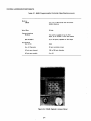
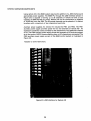
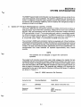
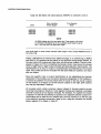
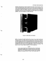
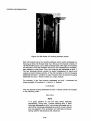
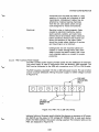
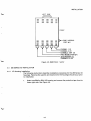
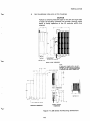
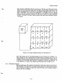
In addition to the STRIP SELECT switches, the half-size 8546 l/O housing contains
two additional sets labeled UPPER BYTE SELECT and LOWER BYTE SELECT.
These switches select, respectively, the upper and lower references for each pair
of modules attached to the housing. Four DIP switches are contained in each set.
To establish the modules’ upper and lower references, one DIP switch is positioned towards the field wiring terminals. For example, the UPPER BYTE SELECT
switch number one selects modules one and two, the next switch selects modules
three and four, etc., concluding with switch number four which selects modules
seven and eight. The LOWER BYTE SELECT switches function in the same
manner.
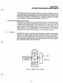
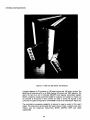
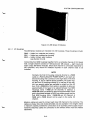
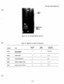
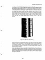
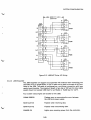
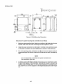
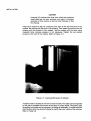
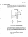
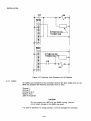
Figure 3-10. 500 Series Field Wiring
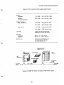
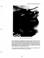
Field wiring, can be connected either before or after the l/O modules are installed.
However, for user convenience, it is recommended that the wiring be installed prior
to inserting the modules. The l/O housing address can be readjusted at any time
the l/O modules are inserted or removed. To set the housing address, the top l/O
module must be removed.
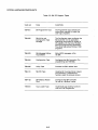
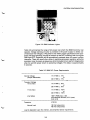
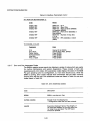
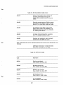
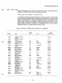
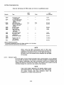
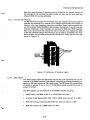
Color-coded adhesive strips are available to identify the field wiring terminals opposite each l/O module, terminal one (top) to eight (bottom). This aids in preventing
a module from being installed in a location not properly wired for the module type.
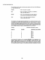
Strips are available for each l/O module. Color codes for the 500 Series modules
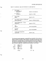
are listed in Table 3-8.
3-23