1
INSTALLATION
NOTE
L
The battery pack cable may be connected or disconnected
with AC power applied to the mainframe and the ON/OFF
switch ON.
l
4.3
5.
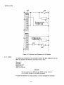
Ensure that BATTERY OK is ON.
6.
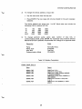
If the RUN light does not energize when the POWER OK indicator is ON, or
if the batteries were not installed for CMOS memories, the controller should
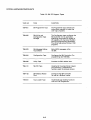
be initialized by one of the following procedures using Modbus Port 2.
a.
Call the Modicon Service Center and use a telephone interface
to enter a new configuration table or a previously stored program.
b.
Use the P190 Programmer and 584M Configurator Tape to design and
load a new configuration table. See P190 Programmer User’s Manual for
details.
C.
Use the P190 Programmer and Tape Loader Tape to load a previously
recorded program. See P190 Programmer User’s Manual for details.
7.
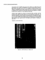
With the RUN light ON, verify the operation of the register access panel.
Examine and/or change a register’s content; examine a discrete input’s state
and/or disable and enable it. Refer to Section 3.2.1 in this manual.
8.
Turn power switch OFF and disconnect power cord.
9.
If the controller fails to operate, call your local Modicon Sales Office. Ensure
that the controller’s serial number, Modicon’s job order, and invoice number
are available for reference.
INSTALLING THE 584M CONTROLLER
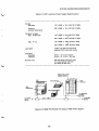
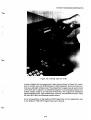
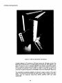
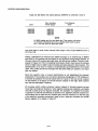
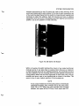
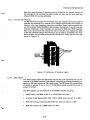
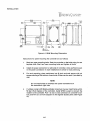
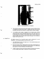
The 584M PC can be installed on any vertical surface capable of supporting its
weight. The 584M can also be mounted in a 19 inch rack configuration without adding special hardware or specifying a different packaging option. It is recommended that the controller be mounted relatively high for easy access to the controller’s display panel. The unit, however, can be placed anywhere in a cabinet or
rack as long as sufficient air flow is possible and the unit is oriented in an upright
position.
Mounting
bolts are
that two
mounting
hardware for the controller is not provided; 5116 x l-112 inch machine
suggested for use with panel mounted units. It is further recommended
workers be assigned when mounting the controller. The controller’s
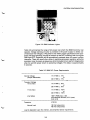
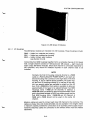
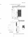
dimensions are displayed in Figure 4-4.
NOTE
Leave a six inch clearance
cables.
4-5
below the controller for l/O