1
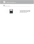
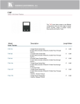
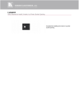
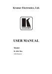
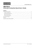
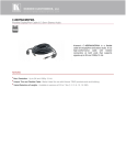
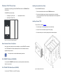
The Kramer T1AF-1T3 Inner Frame
Installing the assembled Inner Frame
Congratulations on purchasing your Kramer T1AF-1T3 inner frame for the TBUS-1Axl Table
Connection bus.
The T1AF-1T3 inner frame includes:
•
An opening for 1 power socket
•
2 openings for 3 Kramer Tools
•
Height adjustment screws
To install the T1AF-1T3 inner frame:
1.
Place the assembled inner frame inside the TBUS-1Axl enclosure.
2.
Set the required height using your fingers to bring the inner frame to the desired
position, screw and tighten it in place using the height adjustment screws supplied with
the inner frame.
Installing a Kramer TOOL
To install a TOOL, as shown in Figure 2:
1.
Screw the spacers to their designated places (one on each side).
2.
Insert the TOOL, from beneath, through the TOOL opening.
3.
Screw the screws (one on each side) through the frame holes and spacers.
Figure 1: T1AF-1T3 Inner Frame (P/N: 80-005199)
Power Socket and Power Cord Options
Various power sockets and power cords are available to use with the T1AF-1T3, as described
in the “TBUS Modular Power Socket Installation and Power Cord” Installation Instructions,
supplied with the power socket.
i
Each power socket comes with detailed assembly instructions.
The T-2INSERT Kit Option (80-00006699)
You can install the T-2INSERT kit (which includes 1 pass-through insert and a blank insert)
instead of a power socket.
The T-TBLANK TOOL Blank Option (80-005099)
You can use the T-TBLANK to cover the TOOL opening.
Figure 2: Installing the Kramer TOOL
Connecting the Cables
KRAMER ELECT RONICS LT D.
To connect the cables:
1.
Insert the cables to their appropriate connectors from underneath.
2.
Secure the cables to the tie holes on the TBUS-1Axl.
Do not secure the cables too tightly or too loosely. Leave a small amount of slack.
Installation
Instructions
After the TBUS-1Axl is connected to mains power and the proper cables, it is ready for use.
Adjusting the Height of the Inner Frame
If needed, you can adjust the inner frame height to accommodate large or bulky cables. To
MODEL:
adjust, perform the following:
1.
Remove the height adjustment screws, while supporting the frame from underneath with
your fingers.
2.
Raise or lower the connecting surface to the required height, insert the screws, and
tighten them in place.
T1AF-1T3
Inner Frame
For the latest information on our products and a list of Kramer
distributors, visit our Web site where updates to this user manual may be
found.
We welcome your questions, comments, and feedback.
Web site: www.kramerelectronics.com
E-mail: [email protected]
!
SAFETY WARNING
Disconnect the unit from the power
supply before opening and servicing
P/N: 2900-300168 Rev 1