1
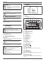
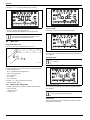
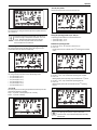
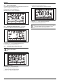
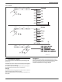
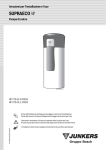
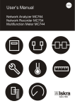
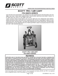
Installation and operating instructions
SUPRAECO W
Heat pump
6720645393-00.1V
HP 270...
Please read the installation instructions before installing the appliance!
Please read the operating instructions before commissioning the appliance!
6 720 646 161 (2012/04) BD-en
Please observe the safety instructions in the operating instructions!
The installation location must meet the requirements for sufficient ventilation!
Installation must only be carried out by an authorised contractor!
Table of Contents
Table of Contents
1
Key to symbols and safety instructions . . . . . . . . . . . . . . . . . . . 3
1.1
Key to symbols . . . . . . . . . . . . . . . . . . . . . . . . . . . . . . . . . 3
1.2
Safety instructions . . . . . . . . . . . . . . . . . . . . . . . . . . . . . . 3
2
Standard delivery . . . . . . . . . . . . . . . . . . . . . . . . . . . . . . . . . . . . . 4
3
Information about the appliance . . . . . . . . . . . . . . . . . . . . . . . . . 5
3.1
Intended use . . . . . . . . . . . . . . . . . . . . . . . . . . . . . . . . . . 5
3.2
Overview of boiler types . . . . . . . . . . . . . . . . . . . . . . . . . 5
3.3
Type plate . . . . . . . . . . . . . . . . . . . . . . . . . . . . . . . . . . . . . 5
3.4
Description of appliance . . . . . . . . . . . . . . . . . . . . . . . . . 5
3.5
Accessories (not included in standard delivery) . . . . . . 5
3.6
Dimensions and minimum clearances . . . . . . . . . . . . . . 6
3.7
Appliance layout . . . . . . . . . . . . . . . . . . . . . . . . . . . . . . . 7
3.8
Electrical wiring diagram . . . . . . . . . . . . . . . . . . . . . . . . . 8
3.9
Refrigerant circuit . . . . . . . . . . . . . . . . . . . . . . . . . . . . . . 9
3.10
Safety, control and protective devices . . . . . . . . . . . . 10
3.10.1 High-pressure/low-pressure pressure switch . . . . . . 10
3.10.2 High limit safety cut-out . . . . . . . . . . . . . . . . . . . . . . . . 10
3.10.3 Temperature sensor for air inlet . . . . . . . . . . . . . . . . . 10
3.11
Corrosion protection . . . . . . . . . . . . . . . . . . . . . . . . . . 10
3.12
Specification . . . . . . . . . . . . . . . . . . . . . . . . . . . . . . . . 11
3.13
System scheme . . . . . . . . . . . . . . . . . . . . . . . . . . . . . . 12
3.13.1 Heat pump for DHW heating with boiler support . . . . 12
3.13.2 Heat pump for DHW heating with solar thermal
system support . . . . . . . . . . . . . . . . . . . . . . . . . . . . . . . 13
4
Transport and storage . . . . . . . . . . . . . . . . . . . . . . . . . . . . . . . 13
5
Installation . . . . . . . . . . . . . . . . . . . . . . . . . . . . . . . . . . . . . . . . . 14
5.1
Installation location . . . . . . . . . . . . . . . . . . . . . . . . . . . 14
5.2
Secure the appliance . . . . . . . . . . . . . . . . . . . . . . . . . . 14
5.3
Installing the air ducts . . . . . . . . . . . . . . . . . . . . . . . . . 15
5.3.1 Open flue operation . . . . . . . . . . . . . . . . . . . . . . . . . . . 15
5.3.2 Functioning with outside air . . . . . . . . . . . . . . . . . . . . 15
5.4
Installation . . . . . . . . . . . . . . . . . . . . . . . . . . . . . . . . . . 15
5.5
Connection for the internal indirect coil . . . . . . . . . . . 16
5.6
DHW circulation . . . . . . . . . . . . . . . . . . . . . . . . . . . . . . 16
5.7
Condensate hose connection . . . . . . . . . . . . . . . . . . . 16
5.8
Expansion vessel (accessories not included in
standard delivery) . . . . . . . . . . . . . . . . . . . . . . . . . . . . . 16
5.9
Filling the storage tank . . . . . . . . . . . . . . . . . . . . . . . . 16
5.9.1 Water characterisitcs . . . . . . . . . . . . . . . . . . . . . . . . . . 17
6
Electrical Connections . . . . . . . . . . . . . . . . . . . . . . . . . . . . . . . 17
6.1
Appliance's electrical connection . . . . . . . . . . . . . . . . 18
7
Commissioning . . . . . . . . . . . . . . . . . . . . . . . . . . . . . . . . . . . . . 18
7.1
Before commissioning . . . . . . . . . . . . . . . . . . . . . . . . . 18
7.2
Switching the appliance on/off . . . . . . . . . . . . . . . . . . 18
8
Operation . . . . . . . . . . . . . . . . . . . . . . . . . . . . . . . . . . . . . . . . . . 18
8.1
Working display . . . . . . . . . . . . . . . . . . . . . . . . . . . . . . 18
8.2
Working modes . . . . . . . . . . . . . . . . . . . . . . . . . . . . . . 18
2
8.3
8.3.1
8.3.2
8.3.3
8.3.4
8.4
8.5
8.5.1
8.5.2
8.5.3
8.5.4
8.5.5
8.5.6
8.6
8.7
8.8
8.9
8.10
9
„Operating“ menu . . . . . . . . . . . . . . . . . . . . . . . . . . . . . 19
„manual“ mode . . . . . . . . . . . . . . . . . . . . . . . . . . . . . . . 19
„P1“, „P2“ and „P3“ modes . . . . . . . . . . . . . . . . . . . . . . 19
„Full“ mode . . . . . . . . . . . . . . . . . . . . . . . . . . . . . . . . . . 19
„Off“ mode . . . . . . . . . . . . . . . . . . . . . . . . . . . . . . . . . . . 19
Setting the DHW temperature . . . . . . . . . . . . . . . . . . . 19
„Main“ menu . . . . . . . . . . . . . . . . . . . . . . . . . . . . . . . . . . 20
„Mode“ function - heating modes . . . . . . . . . . . . . . . . . 20
„Prog“ function - Timetable operation programming . 21
„Leg“ function - automatic thermal disinfection . . . . . 22
„Set“ function - adjustments . . . . . . . . . . . . . . . . . . . . . 23
„Purg“ function - purge . . . . . . . . . . . . . . . . . . . . . . . . . 23
„Info“ function - information . . . . . . . . . . . . . . . . . . . . . 23
Troubleshooting . . . . . . . . . . . . . . . . . . . . . . . . . . . . . . 23
Factory configurations . . . . . . . . . . . . . . . . . . . . . . . . . 24
Selecting the temperature units - „°C“ or „°F“ . . . . . . . 24
Setting the time and day of the week . . . . . . . . . . . . . . 24
Controls . . . . . . . . . . . . . . . . . . . . . . . . . . . . . . . . . . . . . 25
Environment / disposal . . . . . . . . . . . . . . . . . . . . . . . . . . . . . . . 25
10 Maintenance . . . . . . . . . . . . . . . . . . . . . . . . . . . . . . . . . . . . . . . . 26
10.1
General inspections . . . . . . . . . . . . . . . . . . . . . . . . . . . . 26
10.2
Performance check . . . . . . . . . . . . . . . . . . . . . . . . . . . . 26
10.3
Checking/replacing the magnesium anode . . . . . . . . . 26
10.4
Cleaning . . . . . . . . . . . . . . . . . . . . . . . . . . . . . . . . . . . . . 26
10.5
Condensate hose . . . . . . . . . . . . . . . . . . . . . . . . . . . . . . 26
10.6
Safety valve . . . . . . . . . . . . . . . . . . . . . . . . . . . . . . . . . . 26
10.7
Refrigerant circuit . . . . . . . . . . . . . . . . . . . . . . . . . . . . . 27
10.8
High limit safety cut-out . . . . . . . . . . . . . . . . . . . . . . . . 27
10.9
Draining the storage tank . . . . . . . . . . . . . . . . . . . . . . . 27
11 Display . . . . . . . . . . . . . . . . . . . . . . . . . . . . . . . . . . . . . . . . . . . . . 28
11.1
Faults that are shown on the display . . . . . . . . . . . . . . 28
11.2
Displays . . . . . . . . . . . . . . . . . . . . . . . . . . . . . . . . . . . . . 28
SUPRAECO W – 6 720 646 161 (2012/04)
Key to symbols and safety instructions
1
Key to symbols and safety instructions
1.1
Key to symbols
Warnings
Warnings in this document are framed and identified by
a warning triangle which is printed on a grey
background.
Electrical hazards are identified by a lightning symbol
surrounded by a warning triangle.
Keywords indicate the seriousness of the hazard in terms of the
consequences of not following the safety instructions.
• NOTICE indicates that material damage may occur.
• CAUTION indicates that minor to medium injury may occur.
• WARNING indicates that serious injury may occur.
• DANGER indicates possible risk to life.
Important information
Important information in cases where there is no risk of
personal injury or material losses is identified by the
symbol shown on the left. It is bordered by horizontal
lines above and below the text.
Additional symbols
Symbol
B
Æ
•
–
Meaning
a step in an action sequence
a reference to a related part in the document or to other
related documents
a list entry
a list entry (second level)
Table 1
1.2
Safety instructions
Installation
B Installation must only be carried out by an authorised contractor.
B Do not install the appliance in the following locations:
– outside
– in locations prone to corrosion
– in locations with a temperature below +5 °C
– in potentially explosive locations.
B Check the tightness of all hydraulic connections before connecting
the appliance to the power supply.
B Wait until the appliance is at the installation location to remove it from
its original packaging.
Danger of scalding
B Possible to operate with temperatures higher than 60 °C. Please
install a thermostatic mixing valve on domestic hot water outlet
connection.
Maintenance
B The operator is responsible for the safety and environmental
compatibility of the appliance as well as its maintenance.
B Only authorised contractors are permitted to maintain this appliance.
B Isolate the appliance from the power supply before performing any
maintenance work.
Maintenance and repairs
B Repairs may only be carried out by an authorised heating contractor.
Faulty repairs may pose a danger to the operator and cause
malfunctions in the appliance.
B Only original spare parts must be used.
B Have an authorised contractor perform an annual inspection and
maintain the appliance as needed.
Room/inlet air
Keep the inlet air free of contaminants. It must not contain any of the
following substances:
• corrosive substances (ammonia, sulphur, halogen products, chlorine,
solvents)
• fatty or explosive substances
• aerosol concentrations
Do not connect any other exhaust system to the appliance ventilation
system.
Refrigerant
B Please observe the relevant environmental regulations when using
and reusing refrigerant. Do not allow refrigerant to be discharged into
the environment. Use the refrigerant R134a. It is non-flammable and
does not have a destructive impact on the ozone layer.
B Before working on parts of the refrigerant circuit, remove the
refrigerant to ensure work safety.
Use HFC-134a and PAG-ÖL for maintenance purposes. It contains
fluorinated greenhouse gas and is rated with a greenhouse potential of
1300 in the Kyoto Protocol.
Instructions to the customer
B Explain to the customer how the appliance works and how to operate
it.
B Advise the customer that he/she must not make any modifications to
the appliance or carry out any repairs on it.
Damage due to operator error
Operator errors can lead to injuries and/or material losses.
B Ensure that children never operate this appliance unsupervised or
play with it.
B Ensure that only individuals who can operate this appliance correctly
have access to it.
SUPRAECO W – 6 720 646 161 (2012/04)
3
Standard delivery
2
Standard delivery
1
2
6720645393-03.3V
Fig. 1
[1]
[2]
4
Heat pump
Set of printed documents for the appliance
SUPRAECO W – 6 720 646 161 (2012/04)
Information about the appliance
3
Information about the appliance
Appliances of the HP270 series are heat pumps which use the energy in
the ambient air for domestic hot water (DHW) heating.
3.5
Accessories (not included in standard delivery)
Description
Fixation Brackets to fix ventilation pipes
Part number
7 746 901 002
Expansion vessel 12l
Expansion vessel 18l
Expansion vessel 25l
7 747 204 675
"T" for inlet air source selection
7 746 900 714
Shut-off valve / check valve ¾ “
7 709 500 048
Shut-off valve / check valve 1“
7 709 500 080
Table 2
Weather louvre
7 719 003 334
[HP] Heat pump
[270] Storage tank capacity
[-1] Version
[E] Electronic control unit
[1] Number of internal indirect coils in the storage tank
[F] Floor installation
[I]
Indoor air intake
[V] Vertical installation
[S] Side connections
Roof outlet
7 719 003 366
3.1
Intended use
The appliance may only be used for DHW heating.
Using the appliance for any other purpose will be considered incorrect
use. Junkers accepts no liability for any damage resulting from such use.
The appliance is not suitable for industrial applications. It is approved for
household use only.
3.2
Overview of boiler types
HP
270
3.3
-1
E
1
F
I
V
S
Type plate
The type plate is located on the rear side of the appliance.
There you will find details on the appliance performance, part numbers,
approval data, the coded data of manufacture (FD) and other
specifications.
3.4
7 747 204 676
7 747 204 677
Flexible insulated (thermal and acoustic) ducts - 7 719 003 329
10m
Air inlet and air outlet ducts 500 mm
7 746 900 698
Air inlet and air outlet ducts 1000 mm
7 746 900 702
Air inlet and air outlet ducts 2000 mm
7 746 900 706
45° bend
7 746 900 690
90° bend
7 746 900 694
Table 3
Description of appliance
Appliance for DHW heating with the following features:
• Glass-lined steel storage tank with thermal insulation using rigid
polyurethane foam.
• DHW storage tank corrosion-protected using internal magnesium
anode.
• Separate refrigerant and DHW circuits.
• Heat pump automatically stops in the operating mode "Heat pump"1)
if the air inlet temperature is below
+5 °C or above 35 °C
• High-pressure/low-pressure pressure switch to protect the
refrigerant circuit.
• R134a used as the refrigerant.
• DHW temperatures between 30 °C and 70 °C (the factory setting for
the DHW temperature is 50 °C).
1) Æ Section 8.5.1
SUPRAECO W – 6 720 646 161 (2012/04)
5
Information about the appliance
Dimensions and minimum clearances
60
25
390
724
745
160
362
666.5
296
580
680
865
1225
1800
3.6
6720645393-05.2V
Fig. 2
6
Appliance dimensions
SUPRAECO W – 6 720 646 161 (2012/04)
Information about the appliance
3.7
Appliance layout
11 12
13
26
6
10
9
5
14
23
25
15
6
24
16
5
22
18
20
21
17
3
4
7
2
8
1
3
4
27
2
19
1
6720645393-06.1V
Fig. 3
[1]
[2]
[3]
[4]
[5]
[6]
[7]
[8]
[9]
[10]
[11]
[12]
[13]
[14]
[15]
[16]
[17]
[18]
[19]
[20]
[21]
[22]
[23]
[24]
[25]
[26]
[27]
Heat pump
Cold water inlet - G1¼ “
Internal indirect coil outlet - G1“
Internal indirect coil inlet - G1"
Sensor well for temperature sensor (data for programming unit
for the solar thermal system or central heating)
DHW circulation inlet - G3/4"
DHW outlet G1"
Internal indirect coil
Thermal insulation
Cold water inlet to condenser
Cold water outlet from condenser
Air fan
Evaporator
Condenser (gas/water heat exchanger)
Compressor
Sensor well for DHW temperature sensor
Magnesium anode
Electric heating insert
ON/OFF switch
Adjustable feet (3x)
Air outlet aperture
Air inlet aperture
Condensate outlet
DHW circulation pump
Front casing
Housing ring
Housing lid
Fastening for housing lid
SUPRAECO W – 6 720 646 161 (2012/04)
1
2
menu
-
+
ok
3
6720645393-01.1V
Fig. 4
[1]
[2]
[3]
User interface
Display
Setting buttons
Function/fault display for appliance
7
Information about the appliance
3.8
Electrical wiring diagram
14
1
2
3
13
12
4
M
M
10
11
5
6
7
9
M
8
6720646160-20.1V
Fig. 5
[1]
[2]
[3]
[4]
[5]
[6]
[7]
[8]
[9]
[10]
[11]
[12]
[13]
[14]
8
Temperature sensor for air inlet
Storage tank temperature sensor for DHW
Storage tank temperature sensor for cold water
Power cable
High-pressure pressure switch
Capacitor for compressor
Compressor
Temperature controller for compressor
Low-pressure pressure switch
DHW circulation pump
Air fan
Resistor
Resistor for high-limit safety cut-out
Control unit
SUPRAECO W – 6 720 646 161 (2012/04)
Information about the appliance
3.9
Refrigerant circuit
The refrigerant circuit is a closed system in which the refrigerant R134a
circulates as a heat transfer medium.
The evaporator transfers the heat from the air to the refrigerant circuit,
and the refrigerant evaporates into a gas.
The compressor compresses the refrigerant R134a, thus increasing its
temperature.
Then the heat is transferred via a heat exchanger, also referred to as a
condenser, to the storage tank water. The refrigerant R134a condenses
in the process.
R134a flows through the expansion valve in liquid state with decreasing
pressure. Then it is routed back to the evaporator.
1
2
5
16
15
3
14
4
18
17
13
12
11
6
7
19
10
8
9
6720646160-23.3V
Fig. 6
[1]
[2]
[3]
[4]
[5]
[6]
[7]
[8]
[9]
[10]
[11]
[12]
[13]
[14]
[15]
[16]
Air fan
Evaporator
Compressor
Condenser (gas/water heat exchanger)
NTC temperature sensor (air inlet)
DHW connection
Temperature sensor aperture (data for programming unit for
solar thermal system or central heating)
Internal indirect coil
Cold water inlet
Electric heating insert
NTC temperature sensor (top of storage tank)
DHW circulation pump
NTC temperature sensor (bottom of storage tank)
Dry filter
Expansion valve
Low-pressure pressure switch
SUPRAECO W – 6 720 646 161 (2012/04)
[17] Water purge
[18] High-pressure pressure switch
[19] Magnesium anode
9
Information about the appliance
3.10 Safety, control and protective devices
3.10.1 High-pressure/low-pressure pressure switch
The pressure switch protects the refrigerant circuit from overpressure.
The pressure switch switches off the appliance in the event of
overpressure. An automatic reset occurs as soon as the pressure in the
refrigerant circuit has been regulated.
3.10.2 High limit safety cut-out
The high-pressure safety cut-out ensures that the storage tank's water
temperature does not exceed the prescribed limit. If the temperature
rises above the limit, the heating process is interrupted. The reset is
performed manually by an authorised contractor.
3.10.3 Temperature sensor for air inlet
The temperature sensor measures the temperature of the inlet air in the
evaporator. If the measured value is outside operating temperature
range, DHW production automatically switches from "Combi" operating
mode to "Electrical" operating mode. If the appliance is in "Heat"
operating mode, production is stopped until the measured value is
within operating temperature range.
3.11 Corrosion protection
The internal wall of the DHW storage tank is glass lined (double coating).
As an additional corrosion protection measure, the storage tank is
equipped with an internal magnesium anode. It must be inspected at
regular intervals and replaced if necessary.
First maintenance must be performed 6 months after
installation.
In regions with more corrosive water, special safety measures (filter,
etc.) must be taken, and the magnesium anode must be serviced at
shorter time intervals.
10
SUPRAECO W – 6 720 646 161 (2012/04)
Information about the appliance
3.12 Specification
Unit
HP270...O...
kW
–
kW
2.0
3.5
2.0
m3/h
350/330
°C
+5 ... +35
Refrigerant R134a
g
375
Maximum pressure
bar
27
l
kW
m2
°C
l/day
bar/MPa
kWh/day
270
2.0/4.0
1.5
60/70
1270
10/1
0.96
Power supply voltage
V
230 (+10%/-15%)
Frequency
Hz
50
Electric current (without/with electric heating insert)
Total power consumption
Power consumption (without electric heating insert)
Protection class
IP rating (without/with piping)
General data
A
kW
kW
IP
2.6/11.3
2.6
0.6
I
21/24
dB(A)
45
Dimensions, W x H x D
mm
724 × 1825 × 745
Net weight (without packaging)
kg
143
Operation
Heating output (without electric heating insert)1)
Performance coefficient (COP)1)
Heating output of integrated electric heating insert
Air inlet
Air flow rate (without/with piping)
Operating temperature
Compressor
Domestic Hot Water
Storage tank capacity
Maximum heating output without/with electric heating insert
Area of heat exchanger (internal indirect coil)
Maximum water temperature without/with electric heating insert
Maximum DHW flow rate1)
Maximum operating pressure
Cooling constant in 24 hours, as per DIN 4753 Part 82)
Data on the electrical connecting leads
Sound pressure level (at a distance of 1 m)
Table 4
1) As per EN255-3, 20 °C air, DHW heating from 15 °C to 45 °C
2) 20 °C air, DHW temperature 55 °C
SUPRAECO W – 6 720 646 161 (2012/04)
11
Information about the appliance
3.13 System scheme
3.13.1 Heat pump for DHW heating with boiler support
10
12
3
9
6
1
7
8
13
2
3
4
5
11
6720646160-24.2V
Fig. 7
[1]
[2]
[3]
[4]
[5]
[6]
[7]
[8]
[9]
[10]
[11]
[12]
[13]
12
Additional heating element (f.i. gas boiler)
DHW circulation pump
Cold water inlet
Shut-off valve
Check valve
Safety valve
Expansion vessel
Drain set
Heat pump
DHW connection
Outlet siphon
Mixing valve
Integrated electric heating element
SUPRAECO W – 6 720 646 161 (2012/04)
Transport and storage
3.13.2 Heat pump for DHW heating with solar thermal system support
1
10
2
9
14
12
3
13
6
7
8
15
7
3
4
5
11
6720646160-28.2V
Fig. 8
[1]
[2]
[3]
[4]
[5]
[6]
[7]
[8]
[9]
[10]
[11]
[12]
[13]
[14]
[15]
4
Thermal solar collectors
Solar programming unit
Cold water inlet
Shut-off valve
Check valve
Safety valve
Expansion vessel
Drain set
Heat pump
DHW connection
Outlet siphon
Solar pump station
Container for safety valve drain
Mixing valve
Integrated electric heating element
Transport and storage
NOTICE: Transport damage!
B Avoid tilting the appliance at an angle of more than
45°.
B Take care when handling the appliance.
B To avoid dropping the appliance and damaging
internal components, do not pivot the appliance.
SUPRAECO W – 6 720 646 161 (2012/04)
NOTICE: Transport damage!
B To avoid transport damage, wait until the appliance is
at the installation location to remove the protective
packaging.
B Transport and set down the appliance carefully. Jerky
movements can damage the internal glass-lined
coating, the components and their connections or the
external casing.
B Use straps to prevent the appliance from becoming
scratched.
B Use suitable means of transport to bring the appliance
to the installation location (special car, pallet truck,
etc).
General
The appliance is delivered on a single pallet and is protected against
transport damage by special packaging.
Always store and transport the appliance in its original packaging, in
vertical position (check "tilt label" prior to installation) and with the
storage tank empty. Ambient temperatures of -20 °C to +60 °C are
permissible for storage and transport.
13
Installation
• The plinth of the appliance must be strong enough (the appliance
weighs about 400 kg when the storage tank is filled, with the weight
distributed equally over its 3 adjustable feet).
To ensure faultless operation and easy access to all components and
connections for maintenance and repairs, maintain the minimum
clearances specified in Fig. 10.
430
400
2200
500
6720646160-45.1V
Fig. 9
Manual transport
Fig. 10 Recommended minimum clearances (mm)
5.2
Secure the appliance
B Check the colour of the tilt label.
If it is not blue in the top arrow, remove the shrink wrap and external
protective packaging.
Installation
B Installation must only be carried out by an authorised contractor.
B The heat pump installation must follow the applicable regulations.
B Check that all pipe connections are intact and have not shaken loose
during transportation.
B Check the colour of the "tilt label" on the rear side of the appliance's
packaging. If the label is blue, the appliance cannot be installed and
should be returned on it‘s original packaging.
Transport Control Int´l Gmbh
Am Knick 9,22113 Oststeinbek
Tel: 0049 40 713 84 02
Fax: 0049 40 713 24 94
TIP
BLUE
ARROW
COUNTAIBEDS
INDICATE
IN
TIPPED
NER
MISHAND
S
ORWAS
LED
N
TEL
L
Transp
Am
ort
Knick
Tel: Contro
Fax: 0049
9,22113
0049 40 l Int´l
Oststein
40 713
Gmbh
713 84
24 02 bek
94
TIP N
TELL
BLUE BEDS IN
ARROW INDICATES
COUNTAINER WAS
TIPPED OR
MISHANDLED
N
L
TEL
TIP
MADE IN U.S.A.
PATENT NO.3,926,144
5
MADE IN U.S.A.
PATENT NO.3,926,144
TIP N
TELL
BLUE BEDS IN
ARROW INDICATES
COUNTAINER WAS
TIPPED OR
MISHANDLED
MADE IN U.S.A.
PATENT NO.3,926,144
To bring the appliance into position at the installation location, place
straps around the storage tank.
6720645393-04.2V
IN S
BEDS
WAS
INDICATE
BLUE NER
OR
LED
ARROW
COUNTAI
TIPPED
MISHAND
Gmbh
bek
l Int´l 02
Oststein
84 94
Contro713 24
40 713
ort 9,22113
40
0049
Knick
Transp
0049
Am Tel:
Fax:
MADE IN U.S.A.
PATENT NO.3,926,144
NOTICE: Damage from straps!
B Remove front casing (Æ Fig. 3, [24]).
B Make sure that the straps do not scratch or make
indentations on the surface of the appliance.
B Do not fasten the straps at the resistor (Æ Fig. 3,
[17]) or at the temperature sensor aperture (Æ
Fig. 3, [4]).
Transport Control Int´l Gmbh
Am Knick 9,22113 Oststeinbek
Tel: 0049 40 713 84 02
Fax: 0049 40 713 24 94
6720646160-46.1V
5.1
Installation location
Please note the following when choosing the installation location:
• The appliance must be installed in a dry, frost-free room. Optimum
appliance performance is achieved at room temperatures between
+5 °C and +35 °C.
• Check that the appliance‘s installation area has the required
resistance and alignment.
• The air outlet and air inlet must not be in locations where there is a risk
of explosion from gas, steam or dust.
• If open flue gas appliances are already installed at the installation
location, the appliance may not be operated with room air circulation.
Use of an inlet pipe for fresh air or another facility ensuring that the
inlet air is separate from the gas appliance is mandatory.
• Ensure that condensate drains correctly.
14
Fig. 11
B Lift the appliance from its pallet.
B To correctly align the appliance at the installation location, adjust the
height of the adjustable feet.
To ensure that the system operates faultlessly and the
condensate drains, the appliance must be aligned
vertically. The appliance must not tilt more than 1°,
preferably in the direction of the condensate drain.
NOTICE: Damage in the external casing!
B Do not tilt the appliance more than 20°.
SUPRAECO W – 6 720 646 161 (2012/04)
Installation
5.3
Installing the air ducts
Inlet air can be taken from the room where the appliance is installed,
from another room or from the outside. In the last two cases, ducts must
be assembled in the air inlet.
C1 C2
L2
L4
To ensure maximum appliance performance and avoid
condensation in the outer ducts surface, use thermally
and acoustically insulated ducts.
LT1
Choose a room for the air inlet. Observe the average air temperature and
maximum required air flow rate (Æ Tab. 4). To achieve as little air
resistance as possible, install the air inlet and air outlet ducts (Ø 160
mm) as straight as possible. The length of the ducts for the air inlet and
air outlet must not exceed 6 m. Do not install more than two 90° bends.
For each additional bend, reduce the duct length by 1 m.
Duct length for the air inlet and air outlet
Reduction for each 90° bend
LT
2
L3
L1
Ø 160 mm
6m
1m
Table 5
LT1 = L1+C1+L2
LT2 = L3+C2+L4
To ensure that condensate forming in the air inlet and air outlet ducts
drains from the appliance:
B Install air ducts at a slight angle to the opposite side of the air inlet and
air outlet apertures on the top side of the appliance.
B Limit the pressure drop in the lines to 10 Pa to ensure a minimum inlet
air flow rate of 330 m3/h as well as the stated heating output.
Fig. 13 Corresponding duct length (L)
5.3.1 Open flue operation
If the heat pump can be operated using the air in the installation room,
ensure that the room has a volume greater than 20 m3.
5.3.2 Functioning with outside air
When using outside air, assure that the ducts are protected with the
correct accessories.
2
L = LT1 + LT2
Ø 160mm: L ≤ 6m
5.4
1
6720645393-08.3V
Installation
NOTICE: Damage to the ducts due to improper
handling!
B Do not allow ducts to become contaminated during
installation.
B If necessary, flush the ducts with water prior to
commissioning.
It is advisable to purge the installation beforehand, the
presence of dirt may reduce the flow and, in extreme
cases, cause a blockage.
It is recommended that a water filter be installed at the
the appliance's cold water inlet.
6720645393-07.2V
Fig. 12
[1]
[2]
Air inlet
Air outlet
NOTICE: Corrosion damage to the storage tank's
connections!
If the connections are copper:
B Use an isolation fitting1) for the hydraulic connection.
This extends the service life of the magnesium anode.
1) Accessory not included in standard delivery
B Determine the nominal diameter of the room's water installation.
Please note the current water pressure and the expected pressure
drop.
B Carry out the water installation in accordance with the applicable
regulations. Please observe the local regulations on DHW
installations.
B The water pipes can be rigid or flexible. To avoid corrosion, take into
account the behaviour of the materials used in the pipework and the
connections.
SUPRAECO W – 6 720 646 161 (2012/04)
15
Installation
To avoid heat loss and improve appliance efficiency:
B Insulate all water connections.
Safety valve1)
B Install a safety valve at the appliance's cold water inlet.
If the water inlet pressure is higher than 8 bar - 80% the
allowable maximum value (10 bar) -, install a check
valve. The safety valve is controlled as soon as the water
pressure in the appliance is more than 10 bar. In this
case it must be possible to divert the drain to a container.
NEVER SEAL OFF THE SAFETY VALVE'S DRAIN. Do not
install any accessories between the safety valve and the
appliance's cold water inlet.
NOTICE:
The safety valve drain tube must be installed in a frost
free environment and downwards oriented.
5.5
Connection for the internal indirect coil
The appliance is equipped with an internal indirect coil for backup
heating from solar thermal or central heating systems.
1
2
6720646160-26.1V
Fig. 14 Condensate drain
[1]
[2]
Condensate drain
Outlet siphon
5.8
If DHW temperature in the tank reaches 80 °C, the external controller
must switch off the backup circuit. This is to prevent damage to the heat
pump's refrigerant circuit or failure of the safety temperature limiter.
WARNING: Danger of scalding!
Hot water can cause serious scalding.
B Warn occupants of risk of scalding.
B Install a thermostatic mixing valve to limit the hot
water outlet temperature.
If the internal indirect coil is not used:
B Do not remove the plugs from the internal indirect coil's inlet and
outlet apertures.
DHW temperature sensor in the storage tank
B Install DHW temperature sensor in the correct pipe (Æ Fig. 3, [4]).
B Insulate the pipe to prevent heat loss.
5.6
Expansion vessel (accessories not included in
standard delivery)1)
To prevent water loss from the safety valve, a DHW
expansion vessel can be installed.
B Install the expansion vessel at the cold water connection between the
storage tank and the safety assembly.
Table 6 serves as a reference for the selection of the expansion vessel.
The capacity of the expansion vessel must be selected subject to the
water pressure in the system. Details refer to a storage tank temperature
of 60 °C.
Storage
tank type
Water
pressure in
the system
2
12 l
3
18 l
4
25 l
2
12 l
3
12 l
4
18 l
2
12 l
3
12 l
4
18 l
DHW circulation
With regard to the output, DHW circulation should only be used when it
is really needed. To avoid heat loss through a circulation system
connected to the DHW distributor system, this system must be
controlled using a valve or a similar device.
Heat recovering time will be higher when using a
recirculating system.
5.7
Safety valve
(max.
pressure)
Capacity of the
expansion vessel
corresponding to the
switch-on pressure of
the safety valve
6 bar
HP 270...
8 bar
10 bar
Condensate hose connection
The condensate is drained on the rear side of the appliance.
B Connect the condensate hose1) to the condensate drain (Fig. 14, [1])
to allow the condensate to drain freely.
B Drain condensate via an outlet siphon (Fig. 14, [2]).
Table 6
5.9
Filling the storage tank
NOTICE: Damage to the appliance!
B Prior to commissioning the appliance, fill the storage
tank with water and ventilate it.
1) Accessory not included in standard delivery
16
SUPRAECO W – 6 720 646 161 (2012/04)
Electrical Connections
Check if the purge valve outlet is downwards oriented. If
not:
B Rotate the purge valve clockwise (tightening) to
assure that the outlet is downwards oriented.
B Open DHW connection (Fig. 6, [6]) and one or more hot water taps.
B Open storage tank cold water inlet (Fig. 6, [9]).
Storage tank filling starts.
B Close hot water taps only when water flow is free of air pockets.
B Connect the appliance to the power supply via a connection socket
with an earth conductor.
B Move main switch (on the rear side of the appliance above the power
cable (Æ Fig. 3, [18])) to "I".
B Rotate circulation pump speed selector to position „III“.
B Reopen purge valve for a few seconds to assure the complete purge of
the system..
B Rotate circulation pump speed selector to position „I“.
5.9.1 Water characterisitcs
Usage of water with unsuitable characterisitcs can result in prematurely
failing.
Water hardness (°dH)
Water treatment
3,0 - 11,2
Not required
Table 7 Water hardness
pH
Water treatment
6,5 - 9,5
Not required
< 6,5 or > 9,5
Required
Table 8 pH value
Water conductivity for sacrificial anodes
130 μS/cm - 1500 μS/cm
Table 9 Water conductivity
Enamelled tanks must not be used with completely
desalted, distilled or de-ionised potable water.
6720646160-51.1V
Fig. 15 Circulation pump
6
B Activate „Purg“ function (Æ page 28, section 8.5.6).
CAUTION: Risk of scalding!
B Ensure that draining water from the purge valve
presents no risk to people or property.
Only an authorised contractor is permitted to install the
appliance, connect it to the mains, install the air outlet/
inlet and commission the appliance.
B Open purge valve (Æ Fig. 16, [1]) until water drops out through the
purge valve outlet.
Ensure that water drains correctly.
1
Electrical Connections
2
DANGER: Risk of electric shock!
B Isolate the appliance from the power supply using the
fuse or another protective device before carrying out
any work on electrical parts.
DANGER: Risk of electric shock!The capacitor must
discharge after the appliance has been switched off.
B Wait at least 5 minutes.
Fig. 16 Purge valve
[1]
[2]
Purge valve
Condenser (gas/water heat exchanger)
B Close purge valve.
B Wait for about 5 minutes until „Purg“ mode goes off.
B Rotate circulation pump speed selector to position „I“.
Filling procedure is concluded.
DANGER: Risk of electric shock!To ensure compliance
with all safety requirements, a defective connecting
cable may only be replaced by an authorised contractor.
All control, monitoring and safety equipment of this appliance is fully
wired and tested.
The appliance is set at the factory to a power supply of
230 V.
If, after a few minutes of operation, display shows „E09“,
you should:
B Reset the appliance (Æ page 23, paragraph „Resetting the system“).
B Rotate circulation pump speed selector to position „III“.
B Activate „Purg“ function (Æ page 28, section 8.5.6).
SUPRAECO W – 6 720 646 161 (2012/04)
17
Commissioning
NOTICE:
Fuse protection!
8
Operation
B The wiring diagram must show a separate connection
for the appliance.There must be a 30 mA RCD and
earth conductor.
1
The appliance is already equipped with a cable for the power supply.
Power is supplied via the connecting cable (2 m) and an earthed wall
socket (230 V AC/50 Hz).
2
menu
-
+
ok
3
For safety and maintenance purposes, ensure that the
socket is accessible after installation.
6720645393-01.1V
Fig. 17 Control panel
6.1
Appliance's electrical connection
The electrical connection must meet the current
standards for electrical installations in the country of
use.
[1]
[2]
[3]
Display
Selection keys
Indicator light/ Device error indicator
1
2
3
4
5
6
7
B Connect the appliance to the power supply via a connection socket
with an earth conductor.
8
9
16
10
15
7
Commissioning
7.1
Before commissioning
NOTICE: Starting up the appliance when it has not been
filled with water will damage it beyond repair!
B Only operate the appliance once it has been filled with
water.
B Check whether the storage tank is filled with water.
B Check all fittings for leaks.
B Check the electrical connection.
7.2
Switching the appliance on/off
Switching ON
B Move main switch (on the rear side of the appliance above the power
cable (Æ Fig. 3, [18])) to "I".
After the compressor start-up, the appliance should
work, at least, for 5 minutes before it gets turned off
again.
Switching off
B Move main switch to "0".
NOTICE: Appliance damaging!
Negative temperatures can lead to water freezing.
B Do not disconnect power supply.
B Move main switch to „I“.
B Switch the appliance to „Off“ mode (Æ section 8.3.4,
page 19).
-orB Drain the appliance.
11
14
12
13
6720645393-10.1V
Fig. 18 Display
[1]
[2]
[3]
[4]
[5]
[6]
[7]
[8]
[9]
[10]
[11]
[12]
[13]
[14]
[15]
[16]
8.1
Display
Heating in heat pump mode
External heat (solar or boiler)
Information
Parameter adjustment entry
Error indicator
„Service“ menu entry
Days of the week
„auto/man“ functioning
Indicator light
„Prog“ menu entry
Clock adjustment
Timetable
Consumption
Storage tank sensor positions
„anti-freeze“ function
Working display
Visible display symbol
Device functioning.
Visible display symbol
Device inactive (water temperature remains at previously selected
temperature).
8.2
Working modes
Visible display symbol „
“
Operating periods in accordance with defined programming (P1, P2 or
P3).
Visible display symbol „
“
Permanent operation (24 h/7 days) without defined programming or
„Full“ mode.
18
SUPRAECO W – 6 720 646 161 (2012/04)
Operation
8.3
„Operating“ menu
"Full" mode activation reduces device efficiency, and
should only be selected in the event of need for a rapid
increase in water temperature.
Access the „Operating“ menu
B Press the „menu“ key for no longer than 3 seconds.
menu
-
+
ok
<3s
6720646160-14.1V
Fig. 19 Accessing the „Operating“ menu
6720646160-08.1V
Accessing the „Operating“ menu provides access to the following modes
of operation:
• manual
• P1
• P2
• P3
• Full
• Off
B Use the „+“ or „-“ keys to select the desired working mode.
B Confirm using the „oK“ key
To go back one menu:
B Press the „menu“ key.
-orB Do not press any key for the following 15 seconds.
Fig. 21 „Full“ mode
This mode permits setting the water temperature anywhere between
30 °C and 70 °C.
Two heat sources are used simultaneously until the
desired temperature is reached.
Only electrical heat is used over 60 °C.
Upon reaching the selected water temperature, the device exits „Full“
mode and returns to the mode previously selected.
8.3.4 „Off“ mode
This operating mode disconnects the device. Electrical power is only
activated for the „anti-freeze“ protection function, if necessary.
8.3.1 „manual“ mode
In this working mode, the device functions 24 hours a day, 7 days a
week, until it reaches a selected temperature. Used heat source is
defined using the Mode function (Æ Chapter 8.5.1) of „Main“ menu.
6720646160-10.1V
Fig. 22 Modo „Off“
„Anti-freeze“ function
The electrical power is connected when the water temperature of the
deposit reaches 5 °C. It is disconnected when the water temperature
reaches 10 °C.
6720646160-37.1V
Fig. 20 „manual“ mode
8.3.2 „P1“, „P2“ and „P3“ modes
8.4
Setting the DHW temperature
The water temperature is factory-set at a value of 50 °C.
„P1“ mode
Selecting this menu causes the device to function during the predefined
factory time periods (Æ „„P1“ period„, page 21).
„P2“ and „P3“ mode
Selecting this menu causes the device to function during user-defined
time periods (Æ „„P2“ and „P3“ periods, page 21).
8.3.3 „Full“ mode
In this mode, the device uses two heat sources simultaneously: the heat
pump and electrical power.
SUPRAECO W – 6 720 646 161 (2012/04)
19
Operation
B Press the „+“ or „-“ keys until the desired value is reached.
6720646160-19.1V
6720646160-13.1V
Fig. 23 Setting the temperature
B Press the „ok“ key to confirm the selection.
The selected temperature will blink 3x to signal confirmation.
Fig. 25 „Mode“ function
„Electrical“ mode
In this mode, the only heat source used is electrical power.
The selected value blinks until the selection is validated.
If the selection is not validated within 10 seconds, the
previously selected value will remain active.
8.5
„Main“ menu
Accessing the „Main“ menu
B Press the „menu“ key and hold it down for over 3 secs.
menu
-
+
ok
6720646160-07.1V
Fig. 26 „Electrical“ mode
This mode permits setting the water temperature anywhere between
30 °C and 70 °C.
„Heat pump“ mode
>3s
Water heating is only assured while air inlet is between
5 °C and 35 °C.
6720646160-49.1V
Fig. 24 Accessing the „Main“ menu
Accessing the „Main“ menu provides access to the following functions:
• Mode - „Heating modes“
• Prog - „Timetable operation programming“
• Leg - „thermal disinfection“
• Set - „adjustments“
• Purg - „purge“
• Info - „information“
B Use the „+“ or „-“ keys to select the desired menu.
B Confirm using the „ok“ key
8.5.1 „Mode“ function - heating modes
The „Mode“ function permits selection of 3 different heating modes:
• „Electrical“ mode
• „Heat pump“ mode
• „Combi“ mode
6720646160-06.1V
Fig. 27 „Heat pump“ mode
This mode permits setting the water temperature anywhere between
30 °C and 60 °C.
Very low temperatures trigger activation of the „anti
freeze“ protection function (Æ page 19).
„Combi“ mode
This mode used two heat sources, depending on conditions: the heat
pump or the electrical supply.
20
SUPRAECO W – 6 720 646 161 (2012/04)
Operation
„P2“ and „P3“ periods
The heat pump functions at times preset by the user.
6720646160-09.1V
Fig. 28 „Combi“ mode
This mode permits setting the water temperature anywhere between
30 °C and 70 °C.
If the water temperature inside the tank is less than 60 °C
and the incoming air temperature is between -10 °C and
+35 °C, the heat pump will be used as the sole heat
source. The electrical power will be activated when
these conditions are not achieved.
8.5.2 „Prog“ function - Timetable operation programming
The „Prog“ function permits the heat pump to be programmed for
operation based on the desired timetable only.
6720646160-35.1V
Fig. 31 „P2“ and „P3“ periods
Setting the operating periods to „P2“ and „P3“
4 operating periods will be set in each of the functions:
• 2 periods for days „1 to 5“
• 2 periods for days „6 to 7“
Definition of operating periods
B Access the „P2“ or „P3“ functions (Æsection 8.3).
B Press „ok“.
Display shows the start schedule of the 1st operating period in blink
mode.
6720646160-15.1V
6720646160-39.1V
Fig. 29 „Prog“ function
The „Prog“ function provides access to the following menus:
• „P1“ period (days 1 to 5)
• „P1“ period (days 6 to 7)
• „P2“ period (days 1 to 5)
• „P2“ period (days 6 to 7)
• „P3“ period (days 1 to 5)
• „P3“ period (days 6 to 7)
Fig. 32 Start of 1st operating period
B Use the „+“ and „-“ keys to define the operating start schedule.
B Press „ok“.
Blinking display shows operating stop schedule for the 1st period.
B Use the „+“ and „-“ keys to define the operating duration.
B Press „ok“.
Blinking display shows the start schedule for the 2nd operating
period.
„P1“ period
The heat pump functions during the predetermined factory times. No
other type of alteration is possible:
Days 1 - 5: [00:00 Æ 06:00] and [16:00 Æ 19:00]
Days 6 - 7: [02:00 Æ 08:00]
6720646160-40.1V
Fig. 33 Beginning of the 2nd operating period
6720646160-16.1V
Fig. 30 „P1“ period
SUPRAECO W – 6 720 646 161 (2012/04)
If the start of the 2nd operating period is defined within
the operating period of the 1st period, the end of
operation of the 1st period will be adjusted to the newly
defined value.
21
Operation
B Use the „+“ and „-“ keys to define the operating start schedule of the
2nd period.
B Press „ok“.
Blinking display shows the operating stop schedule for the 2nd period.
B Use the „+“ and „-“ keys to define the operating duration.
B Press „ok“.
Days „1 to 5“ are now set.
6720646160-17.1V
Fig. 36 „Leg“ function
The device is factory set with the function deactivated.
Activation of the disinfection mode temporarily replaces
any defined programming.
6720646160-41.1V
WARNING: Beware of burns!
Hot water can cause serious burns.
Fig. 34 Start of 1st operating period for days „6 to 7“
If there‘s no need for a 2nd working period.
B Select the start schedule and end of functioning for
the same time.
B Repeat the above described operations for the operating periods of
days „6 and 7“.
Completed definition of the 2nd operating period for days „6 and 7“
concludes the definition of the operating periods.
B Thermal disinfection should only be performed
outside normal working hours.
B Warn all users of the danger of burns and the need to
perform thermal disinfection.
The disinfection process will run for a maximum period
of 24h. After this time, if a temperature of 70 °C has not
been reached (due to consumption of hot water during
the disinfection period), the device will automatically
return to the previously selected mode of functioning.
Automatic activation of the „Leg“ function
B Access the Leg function and press „ok“.
Display with blinking indication „
“ active.
B Press „+“.
Display with blinking indication „
“ active.
B Press „ok“.
„Leg“ function activated and blinking 1st day of the week.
1
2
3
4
The hot water temperature is automatically set at 70 °C.
6720646160-38.1V
Fig. 35 Definition of periods
[1]
[2]
[3]
[4]
Start of 1st period
End of 1st period
Start of 2nd period
End of 2nd period
Switching off the operating period
B Select the start schedule and end of functioning for the same time.
The operating period will be switched off.
8.5.3 „Leg“ function - automatic thermal disinfection
The „Leg“ function permits activation/deactivation of the thermal
disinfection process. This bacteria elimination process should be
performed at least once a week.
Define the day of the week for disinfection.
B Select the day, using the „+“ and „-“ keys.
B Press „ok“.
Define the time of disinfection
B Select the time, using the „+“ e „-“ keys.
B Press „ok“.
Upon reaching a temperature of 70 °C, the device returns to the
previously selected mode.
Manual activation of the „Leg“ function
B Access the „Leg“ function and press „ok“.
Display with blinking indication „
“ active.
B Press „ok“.
„Leg“ function activated.
The hot water temperature is automatically set at 70 °C.
22
SUPRAECO W – 6 720 646 161 (2012/04)
Operation
Upon reaching a temperature of 70 °C, the device returns to the
previously selected mode.
The disinfection process will not be repeated until it is
reactivated.
„reset“ consumption
Displays with indication of cumulative consumption.
B Press „-“.
Displays with blinking „del“ indication.
8.5.4 „Set“ function - adjustments
The „Set“ function permits adjustment of the following values:
• Temperature units (Æ Chapter 8.8)
• Time and day of the week (Æ Chapter 8.9).
6720646160-42.1V
Fig. 40 „del“ function
B Press „ok“.
The meter restarts the count.
8.6
6720646160-18.1V
Fig. 37 „Set“ function
8.5.5 „Purg“ function - purge
„Purg“ function is an auxiliary for the system purging process.
Fig. 38 „Purg“ function
Troubleshooting
This device is equipped with a troubleshooting function. Anomaly
indication is performed by means of a code (Table 10, page 28)
corresponding to the error indication symbol in the digital visor (Fig. 18,
[6]) and the blinking of the functioning indicator light. In most cases, the
device will only return to normal functioning following elimination of the
cause of the malfunction and resetting of the device.
To identify the malfunction, see Chapter 11.
6720801967 02 1V
To activate „Purg“ function
B Access „Purg“ function and press „OK“.
B Circulation pump will start functioning. After 5 minutes the appliance
returns to the operating mode previously selected.
menu
-
+
ok
8.5.6 „Info“ function - information
The „Info“ function permits display of the cumulative consumption over
the past 30 days.
6720646160-43.1V
Fig. 41 Error code
Resetting the system
B Press the „ok“ key and hold it down for over 3 seconds.
menu
-
+
ok
6720646160-36.1V
Fig. 39 „Info“ function
Displaying the consumption
B Access the „Info“ function and press „ok“.
Displays cumulative consumption (in kWh).
>3s
6720646160-21.1V
Fig. 42 Resetting the system
SUPRAECO W – 6 720 646 161 (2012/04)
23
Operation
8.7
Factory configurations
Upon definition of the temperature units and timetable, the device will
operate according to the factory set values.
B Confirm the selection using the „ok“ key.
The clock is set and the day of the week begins to blink.
Heating mode: „Combi“ (Æ chapter 8.5.1)
Manual functioning: „manual“ (Æ chapter 8.3)
6720646160-12.1V
Fig. 46 Setting the day of the week
6720646160-37.1V
Fig. 43 Initial menu
8.8
Selecting the temperature units - „°C“ or „°F“
Upon the 1st use, the user must select the temperature unit.
B Press the „+“ or „-“ keys to set the day of the week.
B Confirm the selection using the „ok“ key.
By default, the first day of the week is Monday, the
second is Tuesday, and so on. The definition of the 1st
day of the week can be changed if desired.
6720646160-34.1V
Fig. 44 Selecting the temperature units
B Press the „+“ or „-“ keys to select the temperature unit.
B Confirm the selection using the „ok“ key.
8.9
Setting the time and day of the week
The „am/pm“ selection is only valid if „°F“ is selected as
the unit of temperature.
6720646160-11.1V
Fig. 45 Setting the time
B Press the „+“ or „-“ keys to set the time.
B Confirm the selection using the „ok“ key.
Display shows the minute digits, blinking.
B Press „+“ or „-“ keys to set the minutes.
24
SUPRAECO W – 6 720 646 161 (2012/04)
Environment / disposal
8.10 Controls
menu
-
+
ok
manual
-
+
-
+
-
+
-
+
-
+
-
+
-
+
-
+
-
+
P1
P2
<3s
menu
-
+
P3
Full
Off
ok
Mode
Prog
Leg
>3s
Set
-
+
Purg
menu
-
+
-
+
-
+
Info
ok
>3s
6720646160-47.3V
9
Environment / disposal
Environmental protection is a fundamental corporate strategy of the
Bosch Group.
The quality of our products, their economy and environmental safety are
all of equal importance to us and all environmental protection legislation
and regulations are strictly observed.
We use the best possible technology and materials for protecting the
environment taking account of economic considerations.
Used appliances
Used appliances contain valuable materials that should be recycled.
The various assemblies can be easily dismantled and synthetic materials
are marked accordingly. Assemblies can therefore be sorted by
composition and passed on for recycling or disposal.
Packaging
We participate in the recycling programmes of the countries in which our
products are sold to ensure optimum recycling.
All of our packaging materials are environmentally compatible and can
be recycled.
SUPRAECO W – 6 720 646 161 (2012/04)
25
Maintenance
10
Maintenance
DANGER: Risk of electric shock!
B Isolate the appliance from the power supply using the
fuse or another protective device before carrying out
any work on electrical parts.
B Remove magnesium anode.
10.1 General inspections
Inspect the appliance regularly to identify possible malfunctions.
B Keep the appliance's casing the installation location clean.
B Dust the system regularly using a damp cloth.
This way leaks can be identified and repaired at an early stage.
B Check all fittings for leaks on a regular basis.
10.2 Performance check
The temperature difference between the air inlet and the air outlet must
be 5 - 7 °C.
6720800765-05.1V
If the temperature difference is greater:
B Check the air inlet and air outlet ducts (wrong air flow rate)
Fig. 47 Checking state of magnesium anode
If the temperature difference is smaller:
B Notify a contractor or customer service (the appliance must be tested
to improve its heating output).
10.4 Cleaning
10.3 Checking/replacing the magnesium anode
The appliance is protected against corrosion by an
internal magnesium anode.
B Check and, if necessay, replace the magnesium anode.
B Check and clean the evaporator regularly.
B The air inlet and air outlet apertures must be unobstructed and
accessible.
B Check the air grille, air filter and air ducts regularly and clean them if
necessary.
10.5 Condensate hose
NOTICE: Damage to the appliance!
The magnesium anode must be installed before
commissioning the appliance.
NOTICE: Damage to the appliance!
Check the magnesium anode annually and replace if
required. Appliances operated without this protection
are excluded from our warranty.
B Loosen the link between the tube of the condensers and the
condenser collection parts.
B Check for the presence of any dirt in the part and/or the tube.
B Reassemble the link between the tube and the condenser collection
part.
10.6 Safety valve
B Open the safety valve at least once a month (Æ Fig. 48) to ensure that
it is functional.
The internal wall of the DHW storage tank is coated with a double glass
lining. The coating is designed for normal quality water. When using
more corrosive water, the warranty only applies if additional safety
measures (f.i. dielectric joints) have been taken and the magnesium
anode is checked more frequently.
1
To check the protective anode:
B Isolate the appliance from the power supply.
B Remove front casing.
CAUTION: Risk of scalding!
B Before removing the magnesium anode, drain about
75 litres of water from the storage tank.
2
6720608467-18.2AL
Fig. 48 Safety valve
[1]
[2]
Safety valve
Drain
CAUTION: Risk of scalding
B Ensure that draining water from the safety valve
presents no risk to people or property.
26
SUPRAECO W – 6 720 646 161 (2012/04)
Maintenance
10.7 Refrigerant circuit
NOTICE: Refrigerant leak!
B Repairs to the refrigerant circuit (e.g. to the
compressor, condenser, evaporator, expansion
vessel) may only be carried out by an authorised
contractor.
10.8 High limit safety cut-out
The appliance is equipped with an automatic safety facility. This safety
facility isolates the DHW storage tank from the power supply to prevent
the risk of injury if the DHW storage tank water temperature rises above
a certain limit.
NOTICE: The temperature limiter may only be reset by
an authorised contractor after the fault has been
remedied.
Resetting the high limit safety cut-out
B Remove front casing (Æ Fig. 3, [24]).
B Remove the protective cap from the resistor.
B Press reset button all the way down ( Fig. 49, [1]).
1
2
6720646160-27.1V
Fig. 49 Temperature controller
[1]
[2]
Reset button
Temperature controller
After a fault has been remedied, ensure that the
temperature controller is in the position shown in
Fig. 49.
10.9 Draining the storage tank
CAUTION: Risk of scalding
Check the appliance's DHW temperature before opening
the safety valve.
B Wait until the water temperature has dropped enough
to prevent burns and other damage.
B Isolate the appliance from the power supply.
B Close the water shut-off valve at the cold water inlet and open one
DHW tap.
B Open drain set.
-orB Open safety valve.
B Wait until no more water flows out of the drain set and the appliance
has been completely drained.
SUPRAECO W – 6 720 646 161 (2012/04)
27
Display
11
Display
11.1 Faults that are shown on the display
Installation, maintenance and repairs may only be carried out by an
authorised contractor. The following table lists the fault codes and their
remedies.
Display
E01
Description
Fault in the top storage tank temperature sensor
Solution
Notify authorised contractor
E02
Fault in the bottom storage tank temperature sensor
Notify authorised contractor
E03
Fault in the temperature sensor at the air inlet
Notify authorised contractor
E04
Temperature in storage tank ≥ 80 °C
E05
Not used
Eliminate cause of fault. If the fault continues to occur, notify
an authorised contractor.
Notify authorised contractor
E06
Hold down setting buttons longer than 30 seconds
Release buttons
E07
Not used
Notify authorised contractor
E08
Not used
Notify authorised contractor
E09
Incorrect system purging
Notify authorised contractor
Water shortage for long period (> 12h)
Reset the system
Resistor faulty
Notify authorised contractor
E10
Fault in the high limit safety cut-out
Adjusted temperature in the thermostat below the set point
temperature in the tank
E11
Fault in the fan
Notify authorised contractor
High pressure loss in the air ducts
Leaks in refrigerant circuit
Fault in the compressor
Fault in the expansion valve
Fault in the dry filter
Table 10 Fault codes
11.2 Displays
Display
LEG
Description
Thermal disinfection process running
HOT
Temperature of inlet air ≥ 35 °C
COLD
Temperature of the inlet air ≤ +5 °C
Table 11 Display indications
Bosch Thermotechnik GmbH
Junkersstrasse 20-24
D-73249 Wernau
www.junkers.com
Note
When temperature reaches 70 °C, the appliance goes back to
the mode previously selected
Automatic stop of „Heat pump“ mode when air inlet
temperature is lower than 5 °C or higher than 35 °C