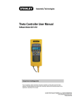
1
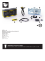
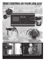
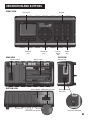
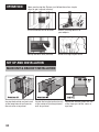
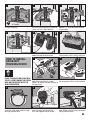
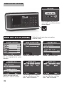
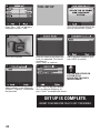
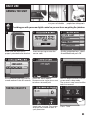
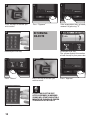
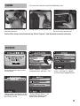
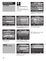
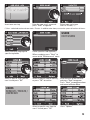
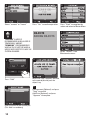
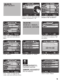
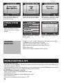
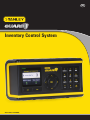
GB
Inventory Control System
stst1-79222, STST310000
B
A
C
G
F
D
E
H
I
A) Main unit
B) Object Tracking Device (Including tie) x5
C) Mounting bracket
D) User tag x5
E) Spare ties x3
F) USB cable
G) Screws (bag)
H) Charger
I) User manual
IMPORTANT: CHARGE BATTERY
Prior to installation unit needs to be charged for at least 12 hours.
Providing you with Stanley Guard Inventory Control System.
You can focus on getting the job done.
Stanley's Inventory control system enables:
• Full command of your valuable equipment at any time and any place.
• Quick and simple installation and setup.
• No more searching after lost expensive equipment.
• Easily track-down in-use tools on the job site.
• Collect Information and statistics about tools usage.
• Easy and intuitive data presentation in the unit or on your computer.
TABLE of contents
getting started
ORIENTATION and buttons
operation
set up and installation
main unit & bracket installation
How to install an object tag
turning system on
Main unit set-up (Wizard)
daily use
ARMING the unit
Taking objects
returning objects
ALARM
RePPORTS
maintenance
settings
Users
objects
turning system off
charging
Trouble shooting, tips & safety
warranty
03
04
04
04
05
06
06
09
09
10
11
11
12
12
12
14
16
16
16
20
TAKE CONTROL OF YOUR JOB SITE
Monitors up to
50 objects
and 30 users
Detection range approximately 25’ / 8m
Checking out tools is quick and easy
system recognizes
unauthorized tool-taking,
AND soundS an alarm
only authorized users can take tools
Orientation and buttons
Front view
LCD display
Keypad
Selection
keys
REAR view
Tamper switch
bottom view
Navigation
keys
Battery cover
Alarm speaker USB & DC jack cover
USB & DC jack sockets
Cancel/
Delete
key
Power
key
Side view
User-tag slot
Communication
port cover
Communication port
03
operation
Upon purchasing the System, just follow these four simple
steps to get it up and running:
Install the Main Unit & Bracket
Attach tracking devices to
your objects
Set-up the Main Unit (Wizard)
Hand user tags to your team
Set up and installation
Main unit & Bracket installation
Locate the bracket and main unit
at the long internal wall next to
the entrance at eye level
04
Locate the bracket and main unit Locate the bracket and main unit
at the center of the long internal at the inner part of the cover at
wall at eye level
eye level
1
2
x 4 units
Components include: bracket,
screws and nuts
4
Tighten the nuts from the inside
How to install
an object
tracking device
Note:
Place the device on your tool.
Select a spot where the device
will not interfere with the
tool’s operation
3
3
Place bracket at the preferred
location, mark the holes and drill
using a 3/16 in./ 5mm drill-bit
5
Insert the screws from the outside.
NOTE: It is also possible to weld
the bracket
6
Slide the main unit over the two
hooks on top of the bracket
Push bottom of main unit against
the bracket until it clicks in place
1
2
Insert a tie-wrap into the upper
Pull the tie-wrap outside until the
hole below the black arrow.
tie-wrap lock clicks at the bottom
(Note : tie wrap may be already in
this position)
4
5
Wrap the tie-wrap around the tool, Push the tie-wrap through the lock Cut the loose end close to the tie’s
and insert the open end through until it comes out of the tag.
hole. Make sure tie-wrap is properly
Pull and tighten the tie-wrap
the tag into the lock
cut to prevent injury
05
turn on THE system
Press the power key until the
system lights up and the welcome
screen appears
Main unit set-up (Wizard)
1
Select “Language” and choose
the main language for the system
interface
4
Confirm the new code and
then press “next” to continue
06
Follow the quick wizard to start working
with the system.
2
Default master code is 12345
5
Use the keypad and navigation
keys to set the date, and then
press “next” to continue
3
Choose a new 5 digit code
6
Use the keypad and navigation
keys to set the time, and then
press “next” to continue
7
8
Note:
this will optimize the
detection range to the
location of your system
Select the option that best fits the
site where the system will be used.
Press “OK” to continue
9
Insert your user tag to the slot
on the right side of the unit
12
Get the tag that you yourself
will be using.
This will be the “Master Tag”
10
Enter your name using the keypad, View the settings and press
and then press “next” to continue “Approve” to continue, or press
“Back” if you need to correct
an entry
13
14
Displays users that are currently
Insert more user tags for your
defined in the system.
employees. You can define up
Press "Add" button to add new user to 30 users
15
Select the user’s Status:
User or Trustee (*), and then press
“OK” to continue
11
16
Select interface language for
a specific tag holder.
Press “OK” to approve
Type each employee’s name and
then press “next”
17
Use the keypad to enter a user’s
trade and then press “next” to
continue (optional)
(*) User – authorized to take and return tools | Trustee – In addition to the above,
can turn the system off and turn off alarms
07
18
TOOL set up
Press the first object device you
wish to upload to the system
Either Press “add” to add more
employees or press “next”
2
Press device button
5
1
3
4
Enter the name of the object you
have just uploaded. (This field is
mandatory).
Press “next” to continue
Add a comment (Optional) and
press NEXT to confirm
6
FOR FURTHER DETAILS ON
SYSTEM SETUP
PLEASE SKIP TO PAGE 12
(MAINTENANCE)
Add the object’s value (Optional)
and press “Approve” to complete
the operation
Select “Add” to add more objects.
You can add up to 50 objects, or
press “finish” to complete the wizard
Set up is complete.
Insert your master TAG to get it working.
08
DAILY USE
ARMING the unit
Check in/out tools
Real time status report Deter unauthorized
at a press of a button people from taking tools
Providing you with your own digital control so you can focus on getting the job done.
1
Make sure the main unit is
properly attached to the bracket
4
Data collection and transition to
armed mode will take 30 seconds
Taking objects
2
Insert master tag or enter the
master code
5
Check the alerts reports.
Remove master tag or press next
to take or return objects
1
Insert your user tag. The system
displays the number of tools in
your posession.
3
Use the navigation keys, select
Armed Mode and press OK
6
Red LED begins to flicker and the
screen enters sleep mode.
The system is now armed and the
tools are secured
2
Press “Take”
09
3
Press the tags of the tool you
wish to take
6
4
Press “Approve”
returning
objects
Remove your user tag
2
Press “Return”
3
Press the tags of the tool you
wish to return
If user tag is left in slot,
after 20 seconds a warning
sound will start and after a
minute the tag will be frozen.
To unfreeze go to page 13
10
If the wrong object was selected,
remove it by pressing “X”
1
Insert your user tag.
The system displays the number
of tool already in your posession.
5
Remove your user tag
5
4
Press “Approve”
ALARM
Unauthorized removal of a tool
from the container
The alarm will sound in any of the following cases.
Cutting the tie-wrap of a tool tag
Unauthorized disconnection of
the main unit from the wall
To turn off the alarm, insert the master tag. Select “Reports” from the master menu for reviewing.
REPORTS
1
Insert your master tag or enter
master code
4
“Alerts report” will display all the
exceptional events that currently
exist in the system
2
3
Select “Reports” using the
navigation keys and press “OK”
“Status Report” will display the
status - missing / in / signed of each of your tagged objects
5
“System Battery Status” will
inform you if the main unit
needs to be recharged
11
1
Maintenance
settings
Only the Master User can
access this menu (using tag or
code).
In maintenance mode, the system is not armed and objects are
not secured
Insert your master tag and select
“Maintenance” from the master
menu
2
3
Select “Settings” and press “OK” Select “Language” and from the
list select the main language for
the system interface
5
4
Select “Date” and enter the
date using the keypad
6
NOTE: Improper location setting
may cause false alarms.
Select “Time” and enter the time
using the keypad
users
Adding users
Select ”Location”- container or
Box, and then press “Back”
to return to “Maintenance” menu
1
Choose “users” from the
Maintenance menu
12
2
Press "Add"
3
Insert new user tag
4
Enter the new user’s name and
press “Next” to approve
5
Select new user’s type:
User or Trustee (*)
(*) User – authorized to take and return tools | Trustee – In addition to the above, can turn the system off and turn off alarms
6
Select interface language for
specific tag holder
1
Select a specific user from the
user list and press “OK”
users
Remove / Freeze /
Unfreeze
7
users
EDIT users
Define specific trade (optional)
When complete, press “Back” to
return to the “Maintenance” menu.
2
Select a specific field for editing,
or press “OK” to confirm
1
Select a specific user from the
users’ list and press “OK”
3
Enter the name of the new user
and press “Next” to approve
Press “ Back” to complete actions
and return to Master Menu
2
Press “Options”
13
3
Select “remove” or “freeze”
4
Press “Yes” to confirm operation
OBJECTS
adding objects
“FREEZING” A USER IS
RECOMMENDED WHEN A USER IS
TEMPORARILY ABSENT.
“REMOVING” IS RECOMMENDED
WHEN A TAG IS LOST OR WHEN A
USER IS NOT EXPECTED TO USE THE
SYSTEM ANYMORE.
2
Press “Add”
5
14
Press “ Back” to complete the
action and return to Master Menu
1
Select “Objects” from
Maintenance menu
3
Make sure a tag is properly attached
to the new object and press the
object’s tag
6
Add comment (Optional) and press
“Next” to confirm
Add Price (Optional) and press
“Approve” to complete
Enter the name of the new object
(This field is mandatory)
5
4
OBJECTS
EDIT OBJECT
1
Select a specific object from the
objects list and press “OK”
3
OBJECTS
Remove / Freeze /
Unfreeze / return
Press “ Back” to complete the
action and return to the Master
Menu
2
Press “options”
2
Select a specific field to edit
and press “OK” to confirm
1
Select a specific object from
the objects list and press “OK”
to confirm
3
Select “Remove” or “Freeze”
5
4
Press “Yes” to confirm operation
6
“FREEZING” an object is
recommended when it is
temporarily MISSING.
“REMOVING” is recommended
when an tracking device is
lost or damaged.
Press “ Back” to complete the
action and return to Master Menu
Select “Return” Object
15
7
Press the chosen object’s tag
button, make sure that tie is
attached to the tag
8
9
System notification will appear
when pressing the right object
When battery is removed or “dead”
the system will request the master
user to update date and time.
Choose “System Off” from the
Master menu
Confirm operation by pressing
“Yes”
turning system
off
NOTE: Only Master user or
Trustee user can turn off the
system
charging
main unit
At normal use , the system is expected to operate at armed mode
for 60 hours before needing to be charged.
Check out "System Battery Status" (See Page 14).
When needed, charge the unit over night (12 hours).
Charge indoor only.
Use only the charger supplied with this system.
trouble shooting & tips
The system does not turn on
• The battery may have depleted. Connect the charger to the DC Jack and make sure the green LED turns on.
Charge the system for 12 hours.
• If you have had the system for more than 2 years, you may need to purchase a new RT645 battery for the system.
• If the system still doesn’t turn on - contact the Stanley Service Center.
The SYSTEM doesn’t recognize a User Tag
• Make sure the system is in Armed Mode and try again.
• If the problem persists:
• Enter Maintenance Mode by using the Master Tag or code.
• Access the User List.
• Select the user who holds the tag and press “OK”.
16
• Select Options and unfreeze the tag.
• If the User Tag is in Unfreeze state, this User Tag is not defined in the system.
• You may re-define the tag in the system.
You forgot your Master Code
• Use your Master Tag to activate the system.
• Enter the Maintenance Menu.
• Change the Master Code.
An employee lost a User Tag
• Enter the Maintenance Mode by using the Master Tag.
• Access the User List.
• Delete the lost user Tag from the authorization database.
You cannot add a new user
• Check the User List in Maintenance Mode, to make sure you did not exceed the limit of 30 users.
• If the database is less than 30 users see above.
You are unable to add a new object to the Objects List
• Make sure a tie-wrap is properly attached to the Object Tracking Device.
• Make sure you did not exceed the limit of 50 Objects.
• If the Object Tracking Device is older than 2 years – its battery may have depleted. See below.
• In any other case, contact the Stanley Support Center.
You connected an Object Tracking Device to a tool with a tie-wrap but the system indicates the tie-wrap is
not connected to the device
• Make sure you have used a Stanley Guard tie wrap that contains a conductive strip which allows the device
to operate.
• Make sure you connected the tie-wrap properly according to the instructions.
• If the problem persists, contact the Stanley Service Center.
You cannot enter Armed Mode
• Make sure that the Main unit is connected to the designated bracket.
• Make sure the bracket presses on the Tamper Switch at the back of the main unit.
• If the problem remains, contact the Stanley Service Center.
The system states that an object is missing although the object is actually present
• Enter the Settings Menu and select Location.
• Make sure the correct location is selected.
• Move object close to the unit and check status report.
The system alerts a tie-wrap has been cut although it is present and uncut.
Check the tie-wrap is correctly attached as defined in the User Manual.
Replace the tie-wrap and re-check the connection.
If the problem persists, contact the Stanley Service Center.
You have lost your charging power supply adaptor; can you use a different power supply?
• No, it is forbidden to use a different kind of adaptor which may cause damage to the battery inside and to
the main system unit.
• Contact the Stanley Support Center in order to purchase a new adaptor.
The system alerts on Low Battery of the Object Tracking Device.
• This is expected after 2 years. The battery is not replaceable. A new Object Tracking Device needs to
be purchased.
By selecting Restore Factory Setting, can you still get LOG data?
• No, all data of the system will be deleted (including user authorization list and objects data) after selecting
Restore Factory Setting. It is highly recommended to download all necessary data to your PC before
performing a System Restore.
You are unable to connect the main unit to your computer
• Make sure your Master Tag is inserted into the main unit.
• Make sure the USB cable is connected properly to your computer.
• Make sure the Stanley Guard software is installed on your computer.
• If the problem persists, contact the Stanley Service Center.
17
tips
• When looking for one of your users in the user list – simply type the user’s first letter and the cursor will
automatically get there.
• When in the object list, you can press the objects device button and the cursor will automatically get there.
• When any of your users is looking for a tool – he can simply insert his user tag and press the 1 button to
view the status report. Thus the user will know if the tool is available and if not, who of his co workers has
checked it out.
• Have you lost your way in the Maintenance Menus? Press the “C” key to return to the previous level.
• When you wish to turn off the system, you can also do so by pressing the ON button for a while. This will
require, of course, a master tag/code or a trustee tag.
general safety rules
WARNING: Read and understand all instructions.
Failure to follow all instructions may result in electric shock, fire, property damage and/or serious personal injury
or death.
WARNING: SERIOUS INJURY OR DEATH.
This product was designed to provide control of property only. Do not use this product to provide protection for life
safety and from fire. Any use other than that suggested in this instruction manual could cause injury or even death.
WARNING: SERIOUS INJURY OR DEATH.
Do not use this product in hazardous areas. This may include blasting areas and potentially explosive
atmospheres. Sparks in such areas could cause an explosion or fire resulting in bodily injury or even death. They
include but are not limited to fueling areas such as gas stations; fuel or chemical transfer or storage facilities;
vehicles using liquefied petroleum gas (such as propane or butane); areas where the air contains chemicals or
particles, such as grain, dust, or metal powders; and any other area where one would normally be advised to
turn off a vehicle engine.
WARNING: SERIOUS INJURY OR DEATH. Consult with manufacturers of any medical devices, such as
pacemakers, hearing aids, etc., to determine if they are susceptible to interference from cellular devices.
WARNING: FIRE, ELECTRIC SHOCK OR ELECTROCUTION.
Do not use an extension cord unless it is absolutely necessary.
Use of an improper extension cord or an extension cord that has been worn or damaged could result in risk of
fire, electric shock or electrocution.
An extension cord must have adequate wire size (AWG or American Wire Gauge) for safety. The smaller the
gauge number of the wire, the greater the capacity of the cable, that is, 16 gauge has more capacity than 18
gauge. When using more than one extension cord to make up the total length, be sure each individual extension
cord contains at least the minimum wire size.
Recommended Minimum Wire Size for Extension Cords
Total Length of Cord 25 ft. 50 ft. 7.6 m 15.2 m
Wire Size AWG 16
The Inventory Control System (ICS) is intended for indoor/outdoor use; power supply is for indoor use only.
Charge indoors.
WARNING: BATTERIES – EXPLOSION, INJURY OR FIRE.
The ICS contains a Lead Acid battery. Carefully follow all of the instructions in this manual.
Never dispose of the ICS or its battery in a fire. Return to a Stanley service center to recycle the unit.
The battery can explode in a fire. Toxic fumes, Hydrogen and materials are created when Lead Acid batteries
are burned.
Lead Acid Batttery can cause severe ACID burns.
Do not disassemble, open, crush, bend, shred, puncture or deform the ICS and its battery.
If battery contents come into contact with the skin, immediately wash area with mild soap and water. If battery
liquid gets into the eye, rinse water over the open eye for 15 minutes or until irritation ceases. In any way seek
18
medical attention.
CAUTION: POTENTIAL EQUIPMENT MALFUNCTION OR FAILURE.
Do not operate with a damaged power supply cord or plug. Damage to the equipment may occur. Protect the
power supply cord from being walked on or pinched particularly at plugs, convenience receptacles and the point
where they exit from the product. Do not pull on cords or cables. When unplugging the cord from an electrical
outlet, grasp and pull the cord by the plug. If a cord or plug is damaged, have it replaced immediately.
CAUTION: POTENTIAL EQUIPMENT MALFUNCTION OR FAILURE. This equipment is supplied with a wall mount
power supply designed specifically to operate on 100-240 V 50/ 60 Hz. If the cord is missing or damaged, replace
only with Stanley power supply specified for this equipment to avoid product damage.
CAUTION: POTENTIAL EQUIPMENT MALFUNCTION OR FAILURE.
To avoid potential damage caused by a power surge, utilize a surge protector.
CAUTION: RISK OF EXPLOSION IF BATTERY IS REPLACED BY AN INCORRECT TYPE.
Dispose of used batteries according to the instructions.
Important Notices
• This product is not user serviceable. There are no user serviceable parts inside the product. Servicing at •
• a STANLEY authorized service center is required to avoid damage to static sensitive internal components. •
• Unauthorized service will void the warranty.
• Clean only with a dry cloth.
• Although the noise level and duration of the siren are below OSHA limits, the loud noise from the sirens may
• startle the user.
Product Limitations
• Although this unit is designed as a personal property protection device, it does not guarantee protection
against burglary or other emergencies. Any alarm is subject to compromise or failure-to-warn for a variety of
reasons including, but not limited to, the following:
• An intruder may gain access through unprotected openings. An intruder with criminal intent, technical
• knowledge, or jamming devices, may bypass the alarm system.
• This product will not operate without power. The equipment has a rechargeable battery. If the battery has not
• been adequately charged, the product will not operate.
• Signals sent by radio may be blocked before they reach the server. Even if the signal path has been recently
• checked during a routine test, blockage can occur if the cellular signal is lost.
• An RFID signal is needed to arm, disarm, accept programming changes and transmit alarm signals. If reception
is not available, equipment is out of service.
• This product is a self-installed alarm. Carefully follow all instructions. Improper installation may compromise
the operation of this equipment.
• This alarm should be tested regularly to make sure all sensors and the RFID signal are working properly.
• Warning devices such as sirens may not alert people if they are out of range. Persons may not hear the
warning • if the alarm is muffled by a radio, operating equipment, appliances or passing traffic. Alarm warning
devices, however loud, may not warn hearing-impaired people.
• Despite advanced design and regular testing, this equipment, like other electrical devices, is subject to
• component failure.
• Installing this alarm may make one eligible for lower insurance rates, but an alarm is not a substitute
for insurance.
Standards:
Area
EU
EU
EU
USA
Canada
USA
Type
Safety
Radio
Radio
Safety
Safety
Radio
Standard
EN 609050-1
EN 300328
EN 300330
UL 60950-1
CSA CS22.2 60950-1
FCC Part 15, Sub-Part B, C
FCC ID GDOICS310000 FCC ID GDOICS311000
USA Energy California Code of Regulations Title 20, Section 1601 to 1608
19
LIMITED ONE YEAR WARRANTY
This warranty covers manufacturing defects in materials or workmanship of your new Stanley
Guard Inventory Control System.
This warranty lasts for a period of one (1) year from the date of original purchase and is only
available to the original purchaser.
Stanley will, at its discretion, repair or replace any malfunctioning system part of your new
Stanley Guard Inventory Control System.
In order to obtain warranty service, you must contact Stanley customer service in
your country within one (1) year of the date of original purchase. A customer service
representative will assist you with warranty service in accordance with this warranty. You
must also provide a copy of the original purchase receipt, your name and address, as well as
a short written description of the product's defect.
Service centers contact information is listed.
This warranty does not cover any problem with the system relating to misuse, abuse, normal
wear and tear, failure to maintain, or an act of nature. This warranty does not cover any other
aspect or portion of your Stanley Guard Inventory Control System. Also, this warranty does
not cover, and Stanley is not liable for, the loss or damage of any of your property.
By purchasing the Stanley Guard Inventory Control System and accepting this warranty, the
purchaser acknowledges that Stanley is not an insurer of any property and that insurance
products are available to the purchaser from other sources to cover such losses.
This warranty does not cover and expressly disclaims all implied warranties of any nature,
including implied warranties of merchantability or fitness for a particular purpose.
Consequential and incidental damages are not recoverable under this warranty. Some
regions do not allow limitations on implied warranties or on consequential or incidental
damages, so the above exclusion may not apply to you. This warranty gives you specific
rights, and you may also have other rights which vary from region to region.
20
Main Unit
Maximum Users 30
Maximum Tools 50
Detection range (Container)* 15-20 Meter
Detection range (Job Box)* 7-10 Meter
Main Radio frequency 2.4Ghz
RFID frequency 125KHz
Battery Type RT645
Battery Capacity 4.5Ah
Battery Voltage 6V
Battery Life Cycle (MAX) 60 Hours
Battery min charging time 12 Hours
Power (Avearge) 75mA / 0.9W
Power (MAX) 170mA / 2W
Operation Temeprature 0-50 C°
Storage Temperature 20-60 C°
Dimensions H 89 X W 126 X L 229 mm
Dimensions
(Including Bracket) H 95 X W 140.3 X L 229 mm
ICS Weight (Average) 1610 gr
ICS Bracket Weight (Average) 515 gr
IP 54
FCC ID GDOICS310000
Regulatory Certifications
Type
Standard
Safety
EN 609050-1
Radio
EN 300328
RadioEN 300330
Safety
UL 60950-1
Safety
CSA CS22.2 60950-1
Radio
FCC Part 15, Sub-Part B, C
Energy
California Code of Regulations Title 20,
Section 1601 to 1608
*Range may veried according to enviroment conditions
Object tracking device
Battery Life Cycle (Shelf life) 3 years
Battery Life Cycle (Average) 2 years
Battery type Lithium 3V - CR2450
Operation Temeprature 0-50 C°
Storage Temperature 20-50 C°
Dimensions
H 32 X W 56.5 X L 45.5 mm (L = 600 mm with tie)
Tie Weight (Average) 13 gr
Radio Frequency 2.4GHz
IP 54
FCC ID GDOICS311000
Regulatory Certifications
Type
Standard
Safety
EN 609050-1
Radio
EN 300328
RadioEN 300330
Safety
UL 60950-1
Safety
CSA CS22.2 60950-1
Radio
FCC Part 15, Sub-Part B, C
User TAG
Dimensions H 6.5 X W 26 X L 76 mm
Weight 10gr
IP 54
FCC STATEMENT:
This equipment has been tested and found to comply with the limits for a class B
digital device, pursuant to Part 15 of the FCC rules. These limits are designed to
provide reasonable protection against harmful interference in a residential installation.
This equipment generates, uses and can radiate radio frequency energy and, if not
installed and used in accordance with the instructions, may cause harmful interference
to radio communications. However, there is no guarantee that interference will not
occur in a particular installation. If this equipment does cause harmful interference to
radio or television reception, which can be determind by turning the equipment off
and on, the user is encouraged to try to correct the interference by one or more of the
following measures:
a) Reorient or relocate the receiving antenna.
b) Increase the seperation between the equipment and receiver.
c) Connect the equipment to an outlet on a circuit different from that to which the
receiver is connected.
d) Consult the dealer or an experienced radio/TV technician.
This device complies with Part 15 of the FCC Rules.
Operation is subject to the following two conditions:
a) This device may not cause harmful interference
b) This device must accept any interference received, including interference that may
cause undesired operation.
FCC Warning
Modifications not expressly approved by the manufacturer could void the user authority
to operate the equipment under FCC Rules.
21
U.S and Canada
1000 Stanley Drive, Concord, NC 28027
Tel: 1-800-262-2161
[email protected]
www.stanleytools.com
Belgique et Luxemburg België en Luxembourg
E. Walschaertstraat 14-16 2800 Mechelen Belgium
NL Tel: +32 15 47 37 63 Fax: +32 15 47 37 99
FR Tel: +32 15 47 37 64 Fax: +32 15 47 37 99
[email protected]
www.stanleytools.eu
Denmark
Farverland 1B 2600 Glostrup
Tlf: 70201510 Fax: 70224910
www.stanleyworks.dk
Deutschland
Richard Klinger Str. 11 65510 Idstein
Tel: 06126-21-1 Fax: 06126-21-2770
www.stanleyworks.de
Ελλάς
Στράβωνος 7 & Βουλιαγμένης 159 Γλυφάδα 1
6674, Αθήνα
Τηλ: +30 210 8981-616 Φαξ: +30 210 8983-285
www.stanleyworks.gr
España
Parque de Negocios “Mas Blau” Edificio Muntadas,
c/Bergadá, 1, Of. A6 08820 El Prat de Llobregat (Barcelona)
Tel: 934 797 400 Fax: 934 797 419
[email protected]
www.stanleyworks.es
France
5, allée des hêtres BP 30084, 69579 Limonest Cedex
Tel: 04 72 20 39 20 Fax: 04 72 20 39 00
[email protected]
www.stanleyoutillage.fr
Schweiz Suisse
In der Luberzen 40 8902 Urdorf
Tel: 01 - 730 67 47 Fax: 01 - 730 70 67
www.stanleyworks.de
Ireland
210 Bath Road; Slough, Berks SL1 3YD UK
Tel: +44 (0)1753 511234 Fax: +44 (0)1753 572112
www.stanleytools.co.uk
Italia
SWK Utensilerie Srl
Energy Park – Building 03 Sud, Via Monza, 7/A
20871 Vimercate (MB)
Tel. 031.780304 – Fax 031.781766
www.stanley.it
Nederlands
Joulehof 12 4600 AB Bergen Op Zoom
Tel: +31 164 28 30 63 Fax: +31 164 28 32 00
[email protected]
Norge
Postboks 4613, Nydalen 0405 Oslo
Tel: 45 25 13 00 Fax: 45 25 08 00
Österreich
Werkzeug Vertriebsges m.b.H
Oberlaaerstrasse 248 A-1230 Wien
Tel: 01-66116-0 Fax: 01-66116-14
www.stanleyworks.de
Portugal
Centro de Escritórios de Sintra Avenida Almirante
Gago Coutinho, 132/134, Edifício 142710-418
Sintra 2710-418 Lisboa
Tel: 214 66 75 00 Fax: 214 66 75 75
[email protected]
Suomi
Tekniikantie 12 02150 Espoo
Puh: 010 400 430 Faksi: 0800 411 340
www.stanleyworks.fi
Sverige
Box 94 431 22 Mölndal
Tel: 031 68 61 00 Fax: 031 68 60 08
Türkiye
KALE Hırdavat ve Makina A.Ş. Defterdar Mah.
Savaklar Cad. No:15
Edirnekapı / Eyüp / İSTANBUL 34050
Tel: 0212 533 52 55 Faks: 0212 533 10 05
United Kingdom
210 Bath Road; Slough, Berks SL1 3YD
Tel: +44 (0)1753 511234 Fax: +44 (0)1753 572112
www.stanleytools.co.uk
Middle East & Africa P.O.Box - 17164, Jebel Ali (South Zone), Dubai, UAE
Tel: +971 4 8127400 Fax: +971-4-8127036
www.stanleyworks.ae
Czech Republic
Stanley Black and Decker Czech Republic
s.r.o. Türkova 5b, 149 00, Prague, CZ Czech Republic
Tel: +420 261 009 779 Fax: +420 261 009 770 Hungary
Stanley Black & Decker Hungary Ltd.
1016 Budapest, Meszaros u. 58/B Hungary
Tel: +36 12 140561
Poland
STANLEY BLACK&DECKER Polska Sp. z o.o. ul.
Postepu 21D 02-676 Warszawa Poland
Tel: 48 22 464-2700 Fax: 48 22 464-2701
Slovakia
Stanley Black & Decker Slovakia s.r.o.
Stará Vajnorská 8 SK-83104 Bratislava, Slovakia
Tel: +421 2 446 38 121,3 Fax: +421 2 446 38 122
Romania
STANLEY BLACK & DECKER
Splaiul Independentei
319 Corp Cladire
Ob. 153-200A Sector 6 0060044 BUCURESTI RO
Tel: +40 21 30 00 755 Fax: +40 21 31 81 126
Bulgaria
EUROTOOLS LTD.
Andrei Liapchev str. 14 1756 Sofia, Bulgaria
Tel: 359-2-4219723 Fax: 359-2-4219723
Tashev Galving LTD 68 Kliment Ohridski BLVD
1756 Sofia, Bulgaria
Slovenia
G-M&M D.O.O. BRVACE 11, SI -1290, GROSUPLJE
Tel. +386(0)17866 500 Fax +386(0)1 7861 205
13399 ICS_manual-GB 07/12
www.stanleytools.com © 2012 Stanley Tools. 701 East Joppa Road, Towson, Maryland 21286
U.S. & Canada Only / E.-U. et Canada seulement
© 2012 Stanley Black & Decker. Egide Walschaertsstraat 14-16, 2800 Mechelen, Belgium. http://www.stanleytools.eu