1
Safety Guidelines
Thank you for purchasing the Mitsubishi programmable controller
MELSEC-L series.
Prior to use, please read this and relevant manuals thorougly to fully
understand the product.
MODEL LJ72MS15-U-HW
MODEL
13J224
CODE
IB(NA)-0800494-C(1405)MEE
© 2013 MITSUBISHI ELECTRIC CORPORATION
SAFETY PRECAUTIONS
(Read these precautions before using this product.)
Before using the MELSEC-L series product, please read this manual and the
relevant manuals carefully and pay full attention to safety to handle the product
correctly.
In this manual, the safety precautions are classified into two levels:
"
WARNING" and "
CAUTION".
WARNING
Indicates that incorrect handling may cause
hazardous conditions, resulting in death or severe
injury.
CAUTION
Indicates that incorrect handling may cause
hazardous conditions, resulting in minor or moderate
injury or property damage.
Under some circumstances, failure to observe the precautions given under "
CAUTION" may lead to serious consequences.
Observe the precautions of both levels because they are important for personal
and system safety.
Make sure that the end users read this manual and then keep the manual in a safe
place for future reference.
All safety precautions for the MELSEC-L series products are described in this
manual.
A-1
[Design Precautions]
WARNING
● Configure safety circuits external to the programmable controller to ensure
that the entire system operates safely even when a fault occurs in the external
power supply or the programmable controller. Incorrect output or malfunction
due to a communication failure may result in an accident.
(1) Emergency stop circuits, protection circuits, and protective interlock
circuits for conflicting operations such as forward/reverse rotations or
upper/lower limit positioning must be configured external to the
programmable controller.
(2) When the programmable controller detects an abnormal condition, it stops
the operation and the output status is as follows:
• If the overcurrent or overvoltage protection of the power supply
module is activated, all outputs are turned off.
• If the self-diagnostics function of the head module detects an error
such as a watchdog timer error, all outputs are held unchanged or
turned off according to the parameter setting.
All outputs may turn on if an error occurs in a part, such as an I/O control
part, where the head module cannot detect any error. To ensure safety
operation in such a case, provide a safety mechanism or a fail-safe circuit
external to the programmable controller. For a fail-safe circuit example,
refer to "GENERAL SAFETY REQUIREMENTS" in this manual.
(3) Outputs may remain on or off due to a failure of an output circuit relay or
transistor. Configure an external circuit for monitoring output signals that
could cause a serious accident.
● In an output circuit, when a load current exceeding the rated current or an
overcurrent caused by a load short-circuit flows for a long time, it may cause
smoke and fire. To prevent this, configure an external safety circuit, such as a
fuse.
● Configure a circuit so that the programmable controller is turned on first and
then the external power supply. If the external power supply is turned on first,
an accident may occur due to an incorrect output or malfunction.
A-2
[Design Precautions]
WARNING
● Configure a circuit so that the external power supply is turned off first and then
the programmable controller.
If the programmable controller is turned off first, an accident may occur due to
an incorrect output or malfunction.
● For the operating status of each station after a communication failure, refer to
relevant manuals for the network. Failure to do so may result in an accident
due to an incorrect output or malfunction.
● When changing data of a running programmable controller from a peripheral
connected to the head module or from an external device such as a personal
computer connected to an intelligent function module, configure an interlock
circuit in the Motion controller program to ensure that the entire system will
always operate safely.
For other controls to a running programmable controller (such as Motion
controller program modification or operating status change), read relevant
manuals carefully and ensure the safety before the operation.
Especially, in the case of a control from an external device to a remote
programmable controller, immediate action cannot be taken for a problem on
the programmable controller due to a communication failure. To prevent this,
configure an interlock circuit in the Motion controller program, and determine
corrective actions to be taken between the external device and head module
in case of a communication failure.
● Do not write any data to the "system area" or "write-protect area" of the buffer
memory in an intelligent function module.
Also, do not turn on any "use prohibited" signal that is output from the head
module to the intelligent function module. Doing so may cause malfunction of
the programmable controller system.
● Laser diodes are used in the optical transceivers of the head module. The
class of these laser diodes (IEC 60825-1) is Class 1. Do not look directly at
laser light. Doing so may harm your eyes.
A-3
[Design Precautions]
WARNING
Precaution specific to digital-analog converter modules
● When a module is faulty, analog outputs may remain on. Configure an
external circuit for monitoring output signals that could cause a serious
accident.
Precaution specific to high-speed counter modules
● Outputs may remain on or off due to a failure of a transistor for external
output. Configure an external circuit for monitoring output signals that could
cause a serious accident.
A-4
[Design Precautions]
CAUTION
● Do not install the control lines or communication cables together with the main
circuit lines or power cables. Keep a distance of 100mm or more between
them. Failure to do so may result in malfunction due to noise.
● During control of an inductive load such as a lamp, heater, or solenoid valve, a
large current (approximately ten times greater than normal) may flow when
the output is turned from off to on.
Therefore, use a module that has a sufficient current rating.
● After the head module is powered on or is reset, the time taken to enter the
RUN status varies depending on the system configuration, and/or parameter
settings. Design circuits so that the entire system will always operate safely,
regardless of the time.
Precautions specific to dual channel isolated high
resolution analog-digital converter modules
● Do not install the analog signal cables together with the main circuit lines;
power cables; or load cables of external devices other than the programmable
controller. Keep a distance of 150mm or more between them.
Failure to do so may result in malfunction due to noise.
Precautions specific to digital-analog converter modules
● When the system is powered on, a surge voltage may occur or inrush current
may flow between output terminals. Start the control after analog outputs are
stabilized.
● Turn on or off the external power supply while the programmable controller is
on. Doing so with the programmable controller is off may cause incorrect
output or malfunction.
A-5
[Installation Precautions]
WARNING
● Shut off the external power supply (all phases) used in the system before
mounting or removing a module. Failure to do so may result in electric shock
or cause the module to fail or malfunction.
[Installation Precautions]
CAUTION
● Use the head module in an environment that meets the general specifications
described in this manual. Failure to do so may result in electric shock, fire,
malfunction, or damage to or deterioration of the product.
● To interconnect modules, engage the respective connectors and securely lock
the module joint levers until they click. Incorrect interconnection may cause
malfunction, failure, or drop of the module.
● Do not directly touch any conductive part and electronic components of the
module. Doing so can cause malfunction or failure of the module.
[Wiring Precautions]
WARNING
● Shut off the external power supply (all phases) used in the system before
wiring.
Failure to do so may result in electric shock or cause the module to fail or
malfunction.
● After installation and wiring, attach the included terminal cover to the product
before turning it on for operation. Failure to do so may result in electric shock.
A-6
[Wiring Precautions]
CAUTION
● Individually ground the FG and LG terminals of the programmable controller
with a ground resistance of 100 or less. Failure to do so may result in electric
shock or malfunction.
● Use applicable solderless terminals and tighten them within the specified
torque range. If any spade solderless terminal is used, it may be disconnected
when a screw on the terminal block comes loose, resulting in failure.
● Check the rated voltage and terminal layout before wiring to the module, and
connect the cables correctly. Connecting a power supply with a different
voltage rating or incorrect wiring may cause a fire or failure.
● Connectors for external device connection must be crimped or pressed with
the tool specified by the manufacturer, or must be correctly soldered.
Incomplete connections could result in short circuit, fire, or malfunction.
● Connect the connector to the module securely.
● Do not install the control lines or communication cables together with the main
circuit lines or power cables. Keep a distance of 100mm or more between
them. Failure to do so may result in malfunction due to noise.
● Place the cables in a duct or clamp them. If not, dangling cables may swing or
inadvertently be pulled, resulting in damage to the module or cables or
malfunction due to poor connection.
● Confirm the interface type in advance and connect the cable correctly.
Connecting a cable to a different interface or incorrect wiring will cause failure
of the module and the external device.
● Tighten the screws on the terminal block within the specified torque range.
Undertightening can cause short circuit or malfunction. Overtightening can
damage the screw and/or module, resulting in drop, short circuit, fire, or
malfunction.
● When disconnecting the cable from the module, do not pull the cable by the
cable part. For a cable with connector, hold the connector by hand and pull it
out. For a cable connected to a terminal block, loosen the terminal block
screws first before removing the cable. Failure to do so may result in
malfunction and damage to the module or cable.
A-7
[Wiring Precautions]
CAUTION
● Prevent foreign matter such as dust or wire chips from entering the module.
Such foreign matter can cause a fire, failure, or malfunction.
● A protective film is attached to the top of the module to prevent foreign matter,
such as wire chips, from entering the module during wiring. Do not remove the
film during wiring. Remove it for heat dissipation before system operation.
● Mitsubishi programmable controllers must be installed in control panels.
Connect the main power supply to the power supply module in the control
panel through a relay terminal block. Wiring and replacement of a power
supply module must be performed by qualified maintenance personnel who is
familiar with protection against electric shock. For wiring methods, refer to the
MELSEC-L CPU Module User's Manual (Hardware Design, Maintenance and
Inspection).
Precaution specific to high-speed counter modules
● Ground the shield cable on the encoder side (relay box). Always ground the
FG and LG terminals to the protective ground conductor. Failure to do so may
cause malfunction.
A-8
[Startup and Maintenance Precautions]
WARNING
● Do not touch any terminal while power is on. Doing so will cause electric
shock or malfunction.
● Shut off the external power supply (all phases) used in the system before
cleaning the module or retightening the terminal block screws or connector
screws. Failure to do so may result in electric shock.
[Startup and Maintenance Precautions]
CAUTION
● Before performing online operations (especially, Motion controller program
modification, forced output, and operation status change) for a running head
module from the peripheral connected, read relevant manuals carefully and
ensure the safety. Improper operation may damage machines or cause
accidents.
● Do not disassemble or modify the modules. Doing so may cause failure,
malfunction, injury, or a fire.
● Use any radio communication device such as a cellular phone or PHS
(Personal Handy-phone System) more than 25cm away in all directions from
the programmable controller. Failure to do so may cause malfunction.
● Shut off the external power supply (all phases) used in the system before
connecting or disconnecting a module. Failure to do so may cause the module
to fail or malfunction.
● Tighten the screws on the terminal block or connector screws within the
specified torque range. Undertightening can cause drop of parts or wires,
short circuit, or malfunction. Overtightening can damage the screw and/or
module, resulting in drop, short circuit, or malfunction.
● After the first use of the module, the number of module connections/
disconnections is limited to 50 times. Exceeding the limit (in accordance with
IEC 61131-2) may cause malfunction.
● Before handling the module, touch a conducting object such as a grounded
metal to discharge the static electricity from the human body. Failure to do so
may cause the module to fail or malfunction.
A-9
[Operation Precautions]
CAUTION
● When controlling a running programmable controller (especially, changing
data, program modification, and operation status change) from an external
device such as a personal computer connected to an intelligent function
module, read the relevant user's manual carefully and ensure the safety
before the operation. Incorrect data change, program modification, and status
control may cause malfunction of the system, mechanical damage, or
accidents.
[Disposal Precautions]
CAUTION
● When disposing of this product, treat it as industrial waste.
A-10
PRÉCAUTIONS DE SÉCURITÉ
(Lire ces précautions avant toute utilisation du produit.)
Avant d'utiliser un produit de la série MELSEC-L, prendre la peine de lire ce
manuel et les autres manuels associés et observer soigneusement toutes les
précautions de sécurité à propos de la manipulation du produit.
Dans ce manuel, les précautions de sécurité sont classées en deux niveaux, à
savoir : "
AVERTISSEMENT" et "
ATTENTION".
AVERTISSEMENT
ATTENTION
Attire l'attention sur le fait qu'une négligence peut
créer une situation de danger avec risque de mort
ou de blessures graves.
Attire l'attention sur le fait qu'une négligence peut
créer une situation de danger avec risque de
blessures légères ou de gravité moyennes ou
risque de dégâts matériels.
Dans certaines circonstances, le non-respect d'une précaution de sécurité
introduite sous le titre "
ATTENTION"peut avoir des conséquences graves.
Les précautions de ces deux niveaux doivent être observées dans leur intégralité
car elles ont trait à la sécurité des personnes et aussi du système.
Veiller à ce que les utilisateurs finaux lisent ce manuel qui doit être conservé
soigneusement à portée de main pour s'y référer autant que de besoin.
Toutes les précautions de sécurité à observer pour les produits de la série
MELSEC-L sont présentées dans ce manuel.
A-11
[Précautions lors de la conception]
AVERTISSEMENT
● Configurer des circuits de sécurité extérieurs à l'automate programmable pour
garantir la sécurité du système dans son ensemble à la survenance d'une
anomalie dans l'alimentation externe comme dans l'automate programmable.
Une sortie erronée ou un dysfonctionnement suite à une erreur de
communication peuvent être à l'origine d'un accident.
(1) Les circuits d'arrêt d'urgence, les circuits de protection et les circuits de
verrouillage de sécurité pour les opérations contradictoires du genre
rotation avant/arrière ou positionnement en limite haute/basse doivent être
configurés à l'extérieur de l'automate programmable.
(2) Lorsque l'automate programmable détecte une situation anormale, il
interrompt la marche et l'état des sorties est comme indiqué ci-après.
• Au déclenchement d'une protection contre surintensité ou surtension
dans le module d'alimentation, toutes les sorties sont mises hors
service.
• Si la fonction d'auto-diagnostic du module de tête détecte une erreur
telle qu'une erreur d'horloge de surveillance, toutes les sorties
peuvent être maintenues sans changement ou mises hors service par
le paramétrage.
Toutes les sorties pourraient rester actives si l'erreur s'est produite dans
une partie comme un organe d'entrée/sortie dont le module de tête ne
peut pas détecter les erreurs. Pour garantir la sécurité en exploitation
dans un telle éventualité, il faut donc prévoir un mécanisme de sécurité ou
un circuit de mise en sécurité à l'extérieur de l'automate programmable.
On trouvera un exemple de circuit de mise en sécurité à la rubrique
"EXIGENCES GÉNÉRALES DU POINT DE VUE DE LA SÉCURITÉ" du
présent manuel.
(3) Après défaillance d'un relais ou d'un transistor de circuit de sortie, les
sorties peuvent restées à l'état actif ou inactif. Configurer un circuit de
surveillance externe pour le suivi des signaux de sortie susceptibles de
provoquer un accident grave.
● Dans un circuit de sortie, si le courant de charge excède la valeur nominale ou
si une surintensité causée par un court-circuit à la charge persiste longtemps,
il peut en résulter un dégagement de fumée avec départ de feu. Pour éviter
cela, il faut configurer un circuit de sécurité, avec un fusible par exemple.
● Configurer le circuit de façon à allumer d'abord l'automate programmable
avant l'alimentation externe. Si on commence par brancher l'alimentation
externe, ceci peut être une cause d'accident en cas de sortie incorrecte ou
autre dysfonctionnement.
A-12
[Précautions lors de la conception]
AVERTISSEMENT
● Configurer un circuit qui coupera d'abord l'alimentation externe puis
l'automate programmable.
Si c'est l'automate programmable qui est mis hors tension en premier, il y a
risque d'accident en cas de sortie erronée ou autre dysfonctionnement.
● Quant à l'état opérationnel de chacune des stations en cas de problème de
communication, voir les manuels correspondants pour le réseau. Faute de
quoi, une instruction de sortie incorrecte ou un dysfonctionnement pourrait
être à l'origine d'un accident.
● Pour pouvoir changer des données dans un automate programmable en
marche à partir d'un périphérique connecté au module de tête ou à partir d'un
dispositif externe comme un ordinateur individuel connecté à un module
fonctionnel intelligent, constituer dans le programme de l'automate contrôlant
les mouvements un circuit de verrouillage permettant de garantir en tous
temps la sécurité de fonctionnement de l'ensemble du système.
Pour les autres interventions sur un automate programmable en marche
(comme par exemple une modification de programme de l'automate
commandant les mouvements), procéder comme indiqué dans les manuels
correspondants et faire les contrôles de sécurité avant d'opérer.
En particulier, lorsqu'un automate programmable distant est commandé à
partir d'un dispositif externe, il faut tenir compte du fait qu'aucune action
immédiate ne sera possible s'il y a un problème de communication avec
l'automate programmable. Pour éviter cela, constituer un circuit de
verrouillage dans le programme de l'automate commandant les mouvements,
et prévoir les mesures correctives à prendre entre le dispositif externe et le
module de tête en cas de problème de communication.
● N'introduire aucune donnée dans les zones réservées "system area" ou
"write-protect area" de la mémoire-tampon d'un module fonctionnel intelligent.
En outre, comme signal de sortie du module de tête vers le module
fonctionnel intelligent, il ne faut utiliser aucun des signaux dont l'usage est
interdit ("use prohibited"). Faute de quoi, il y aura des dysfonctionnements
dans le système de l'automate programmable.
● Les émétteurs-récepteurs optiques du module de tête utilisent des diodes
laser. Ces diodes laser sont de Classe 1 (selon IEC 60825-1). Ne pas
observer le faisceau laser à l'œil nu. Il y aurait risque de lésion oculaire.
A-13
[Précautions lors de la conception]
AVERTISSEMENT
Précautions particulières aux modules convertisseurs
numériques-analogiques
● En as de défaillance d'un module, il se peut que les sorties analogiques
restent actives. Configurer un circuit de surveillance externe pour le suivi des
signaux de sortie susceptibles de provoquer un accident grave.
Précautions particulières au module de comptage hautevitesse
● Les sorties peuvent rester en service ou hors service dans le cas d'une panne
de transistor vers sortie externe. Configurer un circuit de surveillance externe
pour le suivi des signaux de sortie susceptibles de provoquer un accident
grave.
A-14
[Précautions lors de la conception]
ATTENTION
● Ne pas entremêler les lignes de commandes ou câbles de communication
avec les lignes des circuits principaux ou les câbles d'alimentation. Les
installer en maintenant entre eux une distance minimum de 100mm. Faute de
quoi, il y a risque de dysfonctionnement par un bruit.
● À la commande d'une charge inductive comme une lampe, un réchauffeur ou
une électrovanne, un fort courrant (jusqu'à 10 fois l'intensité normale) traverse
la sortie quand celle-ci passe de OFF à ON.
Il faut donc que le module utilisé ait une capacité de courant suffisante.
● À la mise sous tension ou à la réinitialisation du module de tête, le temps
nécessaire à l'entrée en état RUN dépend de la configuration du système et/
ou du paramétrage. Concevoir les circuits de manière que tout le système
fonctionne en sécurité, indépendamment de ce temps.
Précautions d'utilisation des modules convertisseurs
numériques-analogiques haute résolution avec isolation
et double voie
● Ne pas installer les câbles des signaux analogiques avec les lignes des
circuits principaux, ni les câbles d'alimentation ou les câbles de charge des
dispositifs externes autre que l'automate programmable. Les installer en
maintenant entre eux une distance minimum de 150mm. Faute de quoi, il y a
risque de dysfonctionnement par un bruit.
Précautions particulières aux modules convertisseurs
numériques-analogiques
● À la mise sous tension du système, il peut y avoir des crêtes de tension ou
des courants transitoires circulant entre les bornes de sortie. Faire démarrer
la régulation après la stabilisation des sorties analogiques.
● L'alimentation externe doit coupée avec l'automate programmable en marche.
Si l'automate programmable est alors à l'arrêt, il peut y avoir des sorties
erronées ou d'autres dysfonctionnements.
A-15
[Précautions d’installation]
AVERTISSEMENT
● Couper l'alimentation externe du système (sur toutes les phases) avant de
mettre en place ou de retirer un module. Faute de quoi, il y a risque
d'électrocution et le module risque de tomber en panne ou de mal fonctionner.
[Précautions d’installation]
ATTENTION
● Utiliser le module de tête dans un environnement en conformité avec les
spécifications générales que présente ce manuel. Faute de quoi, il a risque
d'électrocution, de départ de feu, de dysfonctionnement, d'endommagement
ou de détérioration du produit.
● Pour l'interconnexion des modules, enficher les connecteurs respectifs et
engager les loquets de module jusqu'à encliquètement. Une interconnexion
imparfaite peut être à l'origine de dysfonctionnements, de pannes ou de
chutes de modules.
● Éviter tout contact direct avec les parties conductrices et les composants
électroniques du module. Une manipulation incorrecte peut être à l'origine de
dysfonctionnements ou de pannes du module.
[Pécautions de câblage]
AVERTISSEMENT
● Avant le câblage, couper l'alimentation externe du système (sur toutes les
phases).
Faute de quoi, il y a risque d'électrocution et le module risque de tomber en
panne ou de mal fonctionner.
● Après installation et câblage, mettre en place les couvre-bornes fournis avec
le produit avant la mise sous tension et la mise en service. Faute de quoi, il y
a risque d'électrocution.
A-16
[Pécautions de câblage]
ATTENTION
● Mettre à la terre individuellement les bornes FG et LG de l'automate
programmable avec une résistance de terre inférieure à 100Ω. Faute de quoi,
il y a risque d'électrocution et de dysfonctionnement.
● Utiliser des bornes sans soudure de type approprié et serrer au couple de
serrage prescrit. Si on utilise des bornes sans soudure de type embrochable,
il y a risque de déconnexion et de panne au cas où une vis de borne se
desserrerait.
● Vérifier la tension nominale et l'affectation des bornes avant le câblage du
module et raccorder les câbles correctement. Le raccordement d'une
alimentation d'une tension autre que la tension nominale ou une erreur de
câblage peut être à l'origine d'un départ de feu ou d'une panne.
● Les connecteurs pour dispositifs externes doivent être sertis en utilisant l'outil
prescrit par le fabricant ou, à défaut, ils seront correctement brasés. Une
connexion imparfaite peut être à l'origine d'un court-circuit ou d'un départ de
feu, ou entraîner des dysfonctionnements.
● Enficher le connecteur fermement sur le module.
● Ne pas entremêler les lignes de commandes ou câbles de communication
avec les lignes des circuits principaux ou les câbles d'alimentation. Les
installer en maintenant entre eux une distance minimum de 100mm. Faute de
quoi, il y a risque de dysfonctionnement par un bruit.
● Les câbles doivent être placés dans un conduit de câbles ou doivent être
attachés. Faute de quoi, le ballottement ou le déplacement des câbles
pourrait endommager le module ou les câbles et être à l'origine de
dysfonctionnements par mauvais contact.
● Vérifier au préalable le type d'interface et raccorder le câble correctement. Le
raccordement d'un câble sur la mauvaise interface ou une erreur de câblage
peuvent être d'une panne du module et du dispositif externe.
● Serrer les vis de la plaque à bornes dans les limites des couples de serrage
prescrit. Un serrage insuffisant peut être à l'origine d'un court-circuit ou de
disfonctionnements. Un serrage excessif peut endommager les vis et/ou le
module, avec aussi un risque de chute, de court-circuits et de
dysfonctionnements.
● Pour débrancher le câble du module, ne tirer directement sur le câble
proprement dit. Si le câble a un connecteur, saisir le connecteur au main et
débrancher en tirant par le connecteur. Pour un câble raccordé sur une
plaque à bornes, desserrer la vis de la borne. Faute de quoi, on pourrait
endommager le module ou le câble et créer un risque de dysfonctionnement.
A-17
[Pécautions de câblage]
ATTENTION
● Veiller à ne pas laisser la poussière, les copeaux métalliques ou d'autres
corps étrangers pénétrer dans le module. De telles corps étrangers peuvent
être à l'origine d'un départ de feu, d'une panne ou d'un dysfonctionnement.
● Le haut du module est recouvert d'un film protecteur pour éviter toute
pénétration de corps étrangers comme des copeaux métalliques pendant le
câblage du module. Ne pas retirer le film protecteur avant de terminer le
câblage. Il doit cependant être retiré avant la mise en service du système pour
une meilleure dispersion de la chaleur.
● Les automates programmable Mitsubishi doivent être installés en tableau ou
armoire de commande. Raccorder l'alimentation principale au module
d'alimentation dans le tableau de commande sur une plaque à bornes avec
relais. Le câblage et le remplacement d'un module d'alimentation doivent être
effectués par un personnel de maintenance qualifié formé à la protection
contre les chocs électriques. Pour la méthode de câblage, se reporter au
Manuel de l'utilisateur du module CPU MELSEC-L (Conception du matériel,
maintenance et inspection).
Précautions particulières au module de comptage
haute-vitesse
● Mettre le câble blindé à la masse du côté codage (boîte à relais). Toujours
mettre à la masse les bornes FG et LG sur le conducteur de protection de
terre. Le non-respect de cette précaution expose à des dysfonctionnements.
A-18
[Précautions de mise en service et de maintenance]
AVERTISSEMENT
● Ne toucher à aucun des bornes quand le système est sous tension. Faute de
quoi, il y a risque d'électrocutions et de dysfonctionnements.
● Couper l'alimentation externe du système (sur toutes les phases) avant le
nettoyage du module ou avant le resserrage des vis de bornes ou des vis de
connecteurs. Faute de quoi, il y a risque d'électrocution.
[Précautions de mise en service et de maintenance]
ATTENTION
● Avant d'effectuer une opération en ligne (en particulier une modification du
programme de l'automate commandant les mouvements, une sortie forcée ou
un changement d'état fonctionnel) sur le module de tête en marche à partir
d'un périphérique connecté, consulter les manuels correspondants pour
opérer en toute sécurité. Une fausse manœuvre pourrait être à l'origine d'un
accident ou de dégâts matériels.
● Ne pas démonter ni modifier les modules. Cela pourrait entraîner des pannes
ou dysfonctionnements et être à l'origine de blessures ou de départs de feu.
● Tout type d'appareil de communication radio, y compris les téléphones
portables et les appareils PHS (Personal handy-phone system), doit être
tenus éloignés de plus de 25cm de l'automate programmable, dans tous les
sens. Le non-respect de cette précaution expose à des dysfonctionnements.
● Couper l'alimentation externe du système (sur toutes les phases) avant de
connecter ou de déconnecter un module. Le non-respect de cette précaution
peut être à l'origine de pannes ou de dysfonctionnements du module.
● Serrer les vis des plaques à bornes et les vis des connecteurs dans les limites
du couple de serrage prescrit. Un serrage insuffisant peut être à l'origine d'un
détachement de pièces ou de fils et entraîner des dysfonctionnements. Un
serrage excessif peut endommager les vis et/ou le module, avec aussi un
risque de chute, de court-circuits et de dysfonctionnements.
● Après mise en service du module (y compris de l'afficheur), le nombre
maximum admissible d'opérations de connexion/déconnexion du module est
de 50. Le dépassement de cette limitation (selon norme IEC 61131-2) peut
être à l'origine de dysfonctionnements.
● Avant de manipuler un module, se débarrasser de la charge électrostatique
qu'accumule le corps humain en touchant un objet conducteur approprié. Le
non-respect de cette précaution peut être à l'origine de pannes ou de
dysfonctionnements du module.
A-19
[Précautions d'exploitation]
ATTENTION
● Pour intervenir sur un automate programmable en marche (en particulier pour
un changement de données, une modification de programme ou un
changement d'état opérationnel) à partir d'un dispositif externe raccordé à un
module fonctionnel intelligent, lire attentivement le manuel de l'utilisateur
avant l'intervention pour pouvoir garantir la sécurité. Tout changement
incorrect dans les données, dans le programme ou dans les états fonctionnels
peut entraîner des dysfonctionnements du système et être à l'origine de
dégâts matériels ou d'un accident.
[Précautions de mise au rebut]
ATTENTION
● Lors de sa mise au rebut, ce produit doit être traité comme un déchet
industriel.
A-20
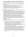
CONDITIONS OF USE FOR THE PRODUCT
(1) Mitsubishi programmable controller ("the PRODUCT") shall be used in
conditions;
i) where any problem, fault or failure occurring in the PRODUCT, if any,
shall not lead to any major or serious accident; and
ii) where the backup and fail-safe function are systematically or
automatically provided outside of the PRODUCT for the case of any
problem, fault or failure occurring in the PRODUCT.
(2) The PRODUCT has been designed and manufactured for the purpose of
being used in general industries.
MITSUBISHI SHALL HAVE NO RESPONSIBILITY OR LIABILITY
(INCLUDING, BUT NOT LIMITED TO ANY AND ALL RESPONSIBILITY
OR LIABILITY BASED ON CONTRACT, WARRANTY, TORT, PRODUCT
LIABILITY) FOR ANY INJURY OR DEATH TO PERSONS OR LOSS OR
DAMAGE TO PROPERTY CAUSED BY the PRODUCT THAT ARE
OPERATED OR USED IN APPLICATION NOT INTENDED OR
EXCLUDED BY INSTRUCTIONS, PRECAUTIONS, OR WARNING
CONTAINED IN MITSUBISHI'S USER, INSTRUCTION AND/OR SAFETY
MANUALS, TECHNICAL BULLETINS AND GUIDELINES FOR the
PRODUCT.
("Prohibited Application")
Prohibited Applications include, but not limited to, the use of the PRODUCT
in;
• Nuclear Power Plants and any other power plants operated by Power
companies, and/or any other cases in which the public could be
affected if any problem or fault occurs in the PRODUCT.
• Railway companies or Public service purposes, and/or any other cases
in which establishment of a special quality assurance system is
required by the Purchaser or End User.
• Aircraft or Aerospace, Medical applications, Train equipment, transport
equipment such as Elevator and Escalator, Incineration and Fuel
devices, Vehicles, Manned transportation, Equipment for Recreation
and Amusement, and Safety devices, handling of Nuclear or
Hazardous Materials or Chemicals, Mining and Drilling, and/or other
applications where there is a significant risk of injury to the public or
property.
A-21
Notwithstanding the above, restrictions Mitsubishi may in its sole discretion,
authorize use of the PRODUCT in one or more of the Prohibited
Applications, provided that the usage of the PRODUCT is limited only for
the specific applications agreed to by Mitsubishi and provided further that
no special quality assurance or fail-safe, redundant or other safety features
which exceed the general specifications of the PRODUCTs are required.
For details, please contact the Mitsubishi representative in your region.
A-22
CONTENTS
1. CHECKING THE INCLUDED ITEMS ............................................................. 1
2. GENERAL SPECIFICATIONS........................................................................ 2
3. CONNECTING THE MODULES..................................................................... 4
3.1 Precautions for Connecting Modules ....................................................... 4
3.2 Connecting Modules................................................................................. 6
3.3 Installing the Modules on a DIN Rail ........................................................ 7
4. EMC AND LOW VOLTAGE DIRECTIVES ................................................... 10
4.1 Requirements for Compliance with the EMC Directive .......................... 11
4.2 Requirements to Compliance with the Low Voltage Directive ................ 20
5. GENERAL SAFETY REQUIREMENTS........................................................ 24
A-23
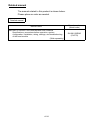
Related manual
The manual related to this product is shown below.
Please place an order as needed.
Detailed manual
Manual name
Manual number
(Model code)
MELSEC-L SSCNET III/H Head Module User's Manual
Specifications, procedures before operation, system
configuration, installation, wiring, settings, and troubleshooting
of the head module
(Sold separately)
SH-081152ENG
(13JZ78)
A-24
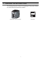
1. CHECKING THE INCLUDED ITEMS
The following items are included in the package of this product. Before
use, check that all the items are included.
Head module + END cover (L6EC)
1
This manual
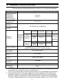
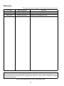
2. GENERAL SPECIFICATIONS
This section provides specifications common to the relevant modules.
Item
Specifications
Operating ambient
temperature
Température
ambiante de
fonctionnement
0 to 55°C
0 à 55 °C
Storage ambient
temperature
Operating ambient
humidity
Storage ambient
humidity
-25 to 75°C
5 to 95%RH, non-condensing
Frequency
Vibration
resistance
Shock resistance
Operating
atmosphere
5 to 8.4Hz
Compliant
Under
with JIS B intermittent
8.4 to
3502 and
vibration
150Hz
IEC
61131-2
5 to 8.4Hz
Under
continuous
8.4 to
vibration
150Hz
Constant
Half
acceleration amplitude
3.5mm
9.8m/s2
1.75mm
4.9m/s2
Sweep
count
10 times
each in
X,Y, and
Z
directions
Compliant with JIS B 3502 and IEC 61131-2
(147m/s2,3 times each in X, Y, and Z directions)
No corrosive gases
Operating
altitude*1
0 to 2000m
Installation
location
Inside control panel
Overvoltage
category*2
II or lower
Pollution degree*3
2 or lower
Equipment
category
Class I
*1 Do not use or store the head module under pressure higher than the atmospheric pressure
at an altitude of 0m. Doing so can cause a malfunction.
To use it in a pressurized environment, please contact your local Mitsubishi representative.
*2 This indicates the level of the power supply (the location ranging from the public power
distribution network to the machinery within premises) that is used to run the equipment.
Category II applies to equipment to which electrical power is supplied from fixed facilities.
The surge voltage withstand level of equipment with rated voltage of up to 300V is 2500V.
2
*3 This index indicates the level of possible conductive pollution in the environment where the
equipment is used.
Pollution degree 2 is non-conductive pollution although a temporary conductivity caused by
condensation can be expected.
POINT
For the product to comply with the EMC or Low Voltage Directive, refer to
Chapter 4.
3
3. CONNECTING THE MODULES
This chapter explains how to connect modules and install them on a
DIN rail.
POINT
(1) Modules must be installed on a DIN rail.
(2) Attach an END cover to the right side of the endmost module.
(3) For installation environment and position of the modules, refer to the
following.
MELSEC-L SSCNETIII/H Head Module User's Manual
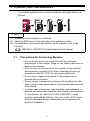
3.1
Precautions for Connecting Modules
• Do not directly touch any conductive part and electronic
components of the module. Doing so can cause malfunction or
failure of the module.
• After the first use of the module, the number of connections/
disconnections is limited to 50 times. Exceeding the limit (in
accordance with IEC 61131-2) may cause malfunction.
• Do not drop or apply strong shock to the module case or
terminal block connector.
• Do not remove a printed-circuit board of the module from the
case. Doing so may cause failure of the module and/or printedcircuit board.
• Consider ease of operation, maintainability, and resistance to
adverse environmental conditions when installing the product in
a control panel, etc. Securely fix all the MELSEC-L series
modules used with the DIN rail. Also refer to the LCPU User's
Manual (Hardware Design, Maintenance and Inspection) for
details of installation.
4
• Prendre en considération la commodité d'exploitation et de
maintenance, ainsi que la bonne résistance aux facteurs
environnementaux adverses lors de l'installation en tableau de
commande, etc. Fixer fermement sur un rail DIN tous les
modules de la série MELSEC-L à utiliser. Pour le détail de
l'installation, voir aussi le MELSEC-L CPU Module User's
Manual (Hardware Design, Maintenance and Inspection)
(Manuel de l'utilisateur MELSEC-L CPU module (conception du
matériel, maintenance et inspection)).
5
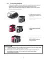
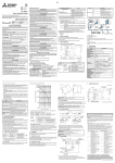
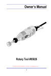
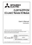
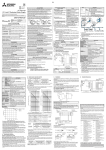
3.2
Connecting Modules
This section explains the procedure for connecting modules with an
example of how to connect the head module with the L61P.
Shut off the external power supply (all phases) used in the system
before connecting modules.
Release
1. To release the module joint levers
located at the top and bottom of the
head module:
Fully slide the levers toward the front
side of the module.
2. Insert the connector of the power
supply module into that of the CPU
module so that they are securely
engaged.
Lock
3. To lock the head module joint levers:
Fully slide the levers toward the back
side of the module.
Make sure that the modules are
securely connected.
POINT
(1) Failure to securely lock the module joint levers until they click may cause
malfunction, failure, and drop of the module.
(2) Metal parts such as the back side of a module may be extremely hot
immediately after power off. Be careful not to get burned when
disconnecting a module.
6
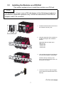
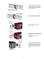
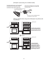
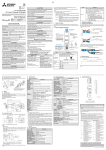
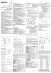
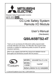
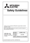
3.3
Installing the Modules on a DIN Rail
This section explains how to install the modules on a DIN rail.
POINT
The description of how to use a DIN rail stopper in the following procedure is
provided for explanation purpose only. Follow the instructions of the DIN rail
stopper used to fix a module.
1. Pull down DIN rail hooks on the back of
the modules until they click.
2. Hang the upper tabs of the modules on
a DIN rail, and push the modules in
position.
Applicable DIN rail model name
(IEC 60715)
• TH35-7.5Fe
• TH35-7.5Al
• TH35-15Fe
3. Lock the DIN rail hooks to the DIN rail
to secure the modules in the position.
Pull the hooks up until they click.
If the hooks are beyond the reach, use
a tool such as a driver.
4. Loosen the screw on DIN rail stopper.
(Use a stopper that is attachable to the
DIN rail.)
(To the next page)
7
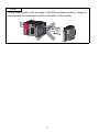
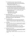
5. Hitch the bottom hook of the DIN rail
stopper to the bottom of the DIN rail.
Check the orientation of the DIN rail
stopper according to the arrow on the
front of the stopper.
Hitch the hook to
bottom of the DIN rail
Hitch the hook to
top of the DIN rail
6. Hitch the upper hook of the DIN rail
stopper to the top of the DIN rail.
DIN rail
stopper
7. Slide the DIN rail stopper to the
leftmost module.
DIN rail
DIN rail
stopper
8. Press the stopper toward the opposite
direction from the arrow incised on the
stopper.
Then tighten the screw with a
screwdriver.
DIN rail
DIN rail
stopper
9. Attach a DIN rail stopper on the right of
the module with the same procedure.
Pay attention when the DIN rail has
been installed on the right side. The
stopper needs to be attached upside
down.
DIN rail
(Right side)
8
POINT
Do not slide modules from the edge of the DIN rail when mounting. Doing so
may damage the metal part located on the back of the module.
9
4. EMC AND LOW VOLTAGE DIRECTIVES
Compliance to the EMC Directive, which is one of the EU Directives,
has been a legal obligation for the products sold in European countries
since 1996 as well as the Low Voltage Directive since 1997.
Manufacturers who recognize their products are compliant to the EMC
and Low Voltage Directives are required to attach a "CE mark" on their
products.
(1)
Authorized representative in Europe
Authorized representative in Europe is shown below.
Name: Mitsubishi Electric Europe BV
Address: Gothaer Strasse 8, 40880 Ratingen, Germany
10
4.1
Requirements for Compliance with the EMC Directive
The EMC Directive specifies that "products placed on the market must
be so constructed that they do not cause excessive electromagnetic
interference (emissions) and are not unduly affected by electromagnetic
interference (immunity)". This section summarizes the precautions on
compliance with the EMC Directive of the machinery constructed with
the MELSEC-L series modules.
These precautions are based on the requirements and the standards of
the regulation, however, it does not guarantee that the entire machinery
constructed according to the descriptions will comply with abovementioned directives.
The method and judgement for complying with the EMC Directive must
be determined by the person who constructs the entire machinery.
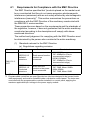
(1)
Standards relevant to the EMC Directive
(a) Regulations regarding emission
Specification
EN61131-2:
2007
Test item
Test details
Standard value
CISPR16-2-3
Radiated
emission*2
Radio waves from the
product are
measured.
• 30M-230MHz
QP: 40dBµV/m (10m in
measurement range)*1
• 230M-1000MHz
QP: 47dBµV/m (10m in
measurement range)
CISPR16-2-1,
CISPR16-1-2
Conducted
emission*2
Noise from the
product to the power
line is measured.
• 150k-500kHz
QP: 79dB, Mean: 66dB*1
• 500k-30MHz
QP: 73dB, Mean: 60dB
*1 QP: Quasi-peak value, Mean: Average value
*2 Programmable controllers are open-type devices (devices designed to be housed inside
other equipment) and must be installed inside a conductive control panel. The tests were
conducted with the programmable controller installed in a control panel, applying the
maximum applicable input voltage to the power supply module.
11
(b) Regulations regarding immunity
Specification
EN61131-2:
2007
Test item
Test details
Standard value
EN61000-4-2
Electrostatic
discharge
immunity*1
Immunity test in
which electrostatic is
applied to the cabinet
of the equipment.
• 8kV Air discharge
• 4kV Contact discharge
EN61000-4-3
Radiated, radiofrequency,
electromagnetic
field immunity*1
Immunity test in
which electric fields
are irradiated to the
product.
80% AM modulation@1kHz
• 80M-1000MHz: 10V/m
• 1.4G-2.0GHz: 3V/m
• 2.0G-2.7GHz: 1V/m
EN61000-4-4
Electrical fast
transient/burst
immunity*1
Immunity test in
which burst noise is
applied to the power
line and signal line.
• AC/DC main power, I/O power,
AC I/O (unshielded): 2kV
• DC I/O, analog, communication
: 1kV
EN61000-4-5
Surge
immunity*1
Immunity test in
which lightning surge
is applied to the
power line and signal
line.
• AC power line, AC I/O power,
AC I/O (unshielded)
: 2kV CM, 1kV DM
• DC power line, DC I/O power
: 0.5kV CM, DM
• DC I/O, AC I/O (shielded),
analog*2, communication: 1kV CM
EN61000-4-6
Immunity to
conducted
disturbances,
induced by
radio-frequency
fields*1
Immunity test in
which high frequency
0.15M-80MHz, 80% AM modulation
noise is applied to the
@1kHz, 10Vrms
power line and signal
line
EN61000-4-8
Powerfrequency
magnetic field
immunity*1
Immunity test in
which the product is
installed in inductive
magnetic field
Immunity test in
EN61000-4-11
which power supply
Voltage dips and
voltage is
interruption
momentarily
immunity*1
interrupted
50Hz/60Hz, 30A/m
• Apply at 0%, 0.5 cycles and zerocross point
• 0%, 250/300 cycles (50/60Hz)
• 40%, 10/12 cycles (50/60Hz)
• 70%, 25/30 cycles (50/60Hz)
*1 Programmable controllers are open-type devices (devices designed to be housed inside
other equipment) and must be installed inside a conductive control panel. The tests were
conducted with the programmable controller installed in a control panel.
*2 The accuracy of an analog-digital converter module may temporary vary within ±10%.
12
(2)
Installation inside a control panel
The programmable controllers are open type devices and must be
installed inside a control panel.
This ensures safety as well as effective shielding of programmable
controller-generated electromagnetic noise.
(a) Control panel
• Use a conductive control panel.
• When securing the top or bottom plate using bolts, cover the
grounding part on the control panel so that the part will not
be painted.
• To ensure electrical contact between the inner plate and
control panel, take measures such as covering the bolts so
that conductivity can be ensured in the largest possible
area.
• Ground the control panel with a thick ground cable so that
low impedance can be ensured even at high frequencies.
• Holes in the control panel must be 10cm diameter or less. If
the holes are larger than 10cm, radio wave may be emitted.
In addition, because radio waves leak through a clearance
between the control panel and its door, reduce the clearance
as much as possible. The leakage of radio waves can be
suppressed by the direct application of an EMI gasket on the
paint surface.
Our tests have been carried out on a panel having the
attenuation characteristics of 37 dB (max.) and 30 dB (mean)
(measured by 3m method, 30 to 300MHz).
(b) Wiring of power cables and ground cables
• Provide a ground point near the power supply module.
Ground the LG and FG terminals of the power supply
module with the thickest and shortest ground cable (30cm or
shorter) possible.
13
(3)
Cables used for the modules connected to the head module
Use shielded cables for the cables which are connected to the I/O
modules and may be extended out of the control panel.
If a shielded cable is not used or not grounded correctly, the noise
immunity will not meet the specified value.
(a) Grounding the shield of the shielded cable
• Ground the shield of the shielded cable as close to the
module as possible so that the grounded cable will not be
affected by electromagnetic induction from ungrounded
cables.
• Ground the exposed shield section to large area on the
control panel. A clamp fitting can be used as shown in
below. In this case, apply a cover on the painted inner wall
surface of the control panel, which comes in contact with the
fitting.
Screw
Clamp fitting
Paint mask
Shielded cable
POINT
Grounding with a vinyl-coated wire soldered onto the shielded section of the
shielded cable as shown below is not recommended. Doing so will raise the
high-frequency impedance, resulting in loss of the shielding effect.
Shielded cable
Vinyl-coated wire
Solderless terminal
14
(b) Grounding the cable clamp
Use shielded cables for external wiring and ground the shields
of the external wiring cables to the control panel with the
AD75CK-type cable clamping (Mitsubishi). (Ground the shield
section 20 to 30cm away from the module.)
Inside the control panel
CPU
20 to 30cm
AD75CK
For details of the AD75CK, refer to the following.
AD75CK-type Cable Clamping Instruction Manual
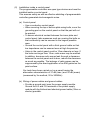
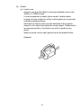
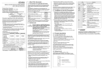
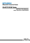
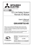
(c) Connectors for external devices
When using connectors for external devices with a high-speed
counter module, take the noise reduction measures described
below.
[Wiring example when using shielded cables]
The following figure shows the example of wiring using
A6CON1 for noise reduction.
Connector
(A6CON1)
External I/O device
Shielded
cable
External I/O device
External I/O device
To the
module
The length between the connector
and the shielded cables should be
the shortest possible.
15
Ground the FG wire of 2 mm2 or more at
the shortest length. (Securely install the
wire to the control panel on the module
side.)
[Example of processing for a shielded cable]
To protect signals, cover connector pins with
heat shrinkable insulation tube. (If signals
are stripped, they are affected by static
electricity and may result in malfunction.)
Take off the insulating tube of each shield
and connect the shields of the cables with
conductive tapes.
Cover the conductive part
with insulating tape.
Pick any one of the shielded cables
and solder it to the FG wire.
[Wiring example when using a duct (Example of a problem and
its solution)]
Wiring duct
Relay
Drive
unit
Relay
Drive
unit
Relay
Control
panel
Noise source
Programmable
controller
(Power system,
etc.)
The drive units are placed
near the noise source. The
connection cable between
the programmable controller
and drive units is too long.
Modified
Wiring duct
Relay
Relay
Relay
Control
panel
Noise source
(Power system,
etc.)
Programmable
controller
Drive
unit
16
Drive
unit
The programmable
controller and drive
units are placed closely.
The connection cable
between them is located
separately from the power
line, and is as short as
possible. (In this example,
the cables are connected
without using the duct.)
(d) I/O signal lines and other communication cables
For the following cables, if pulled out of the control panel,
always ground the shield section of these lines and cables in
the same manner described in (a).
• I/O signal lines (including a common line)
(e) Power cables for external power supply terminal
As an external power supply for the following modules, use a
CE-marked AC/DC power supply with a reinforced insulation
or a double insulation. Install the AC/DC power supply in the
control panel where the module is installed. Keep the length of
the power cable connected to the external power supply
terminal to 30m or less.
• Analog-digital converter module
• Digital-analog converter module
• High-speed counter module
(4)
External power supply
Use a CE-marked external power supply with a reinforced
insulation or a double insulation and ground the FG terminals.
(External power supply used for the tests conducted by Mitsubishi:
TDK-Lambda DLP-120-24-1, IDEC PS5R-SF24)
(5)
Power supply module
• Always ground the LG and FG terminals after shunting them.
• Use a CE-marked external power supply with a reinforced
insulation or a double insulation to supply 24VDC to the L63SP.
(6)
I/O modules
• Install the DC power in the same control panel with the modules.
• When a cable for the DC power is installed extending outside the
control panel, use a shielded cable.
• A cable for the DC power must be 30m or less in length.
• When the number of relay operations is more than 5 times per
minute, take measures such as using a surge suppressor.
(7)
High-speed counter module
• Install the DC power in the same control panel with the modules.
• When a cable for the DC power is installed extending outside the
control panel, use a shielded cable.
• Keep the length of cables connected to external devices to 30m
or less.
17
(8)
Others
(a) Ferrite core
A ferrite core has the effect of reducing radiated noise in the
30MHz to 100MHz band.
It is recommended to attach ferrite cores if shield cables
coming out from pulled out of the control panel do not provide
sufficient shielding effects.
Note that the ferrite cores must be attached at the position
closest to the cable hole inside the control panel. If attached at
an improper position, the ferrite core will not produce any
effect.
Attach a ferrite core to each power line as illustrated below.
Example
18
(b) Noise filter (power supply line filter)
A noise filter is a component which has an effect on conducted
noise.
Attaching the filter can suppress more noise. (The noise filter
has the effect of reducing conducted noise of 10 MHz or less.)
The precautions for attaching a noise filter are described
below.
• Do not bundle the cables on the input side and output side
of the noise filter. If bundled, the output side noise will be
induced into the input side cables from which the noise was
filtered.
Input side
Input side
(power supply (power supply
side)
side)
Induction
Filter
Filter
Output side
(device side)
Output side
(device side)
Noise will be induced when the
input and output wires are bundled.
Separately install the input and
output wires.
• Ground the noise filter grounding terminal to the control
panel with the shortest cable possible (approx. 10cm).
19
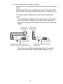
(c) Isolation transformer
An isolation transformer has an effect on reducing conducted
noise (especially, lightning surge).
Lightning surge may cause a malfunction of the programmable
controller.
As measures against lightning surge noise, connect an
isolation transformer as shown below.
Using an isolation transformer will reduce an impact of
lightning.
Main Relay Programmable Isolation
power terminal controller
transformer
supply block power supply
Programmable
controller
100V AC
200V AC
I/O power
supply
T1
I/O equipment
Motor power
supply
Motor equipment
Inside the control panel
4.2
Requirements to Compliance with the Low Voltage
Directive
The Low Voltage Directive requires each device that operates with the
power supply ranging from 50 to 1000VAC and 75 to 1500VDC to
satisfy the safety requirements.
This section summarizes precautions on using the MELSEC-L series
modules to comply with the Low Voltage Directive. These descriptions
are based on the requirements and standards of the regulation;
however, it does not guarantee that the entire machinery manufactured
based on the descriptions complies with the Low Voltage Directive. The
method and judgment for the Low Voltage Directive must be left at
manufacturer's own discretion.
(1)
Standard applied for MELSEC-L series modules
• EN61010-1 Safety of equipment used in measurements,
controls, or laboratories.
The MELSEC-L series modules with a rated voltage of 50VAC and
75VDC or higher have been also developed to conform to the
above standard.
The modules which operate at the rated voltage of less than
50VAC and 75VDC are out of the Low Voltage Directive application
range.
20
(2)
MELSEC-L series module selection
(a) Power supply module
There are dangerous voltages (voltages higher than or equal
to 42.4V peak) inside the power supply modules of 100VAC
and 200VAC rated input voltages. Therefore, for CE-marked
products, insulation is reinforced internally between the
primary and secondary circuits.
(b) I/O modules
There are dangerous voltages (voltages higher than or equal
to 42.4V peak) in the I/O modules of 100VAC and 200VAC
rated I/O voltages. Therefore, for CE-marked products,
insulation is reinforced internally between the primary and
secondary circuits.
The I/O modules of 24VDC or less rating are out of the Low
Voltage Directive application range.
(c) Modules not relevant to the Low and Voltage Directive
Using 5VDC circuit inside, the following modules are out of the
Low Voltage Directive application range.
• Head module
• END cover
The intelligent function modules are out of the scope of the
Low Voltage Directive because the rated voltage is 24VDC or
less.
(3)
Power supply
The insulation specification of the power supply module was
designed assuming Installation Category II.
Satisfy the Installation Category II for the power supply to the
programmable controller.
21
(4)
Control panel
(a) Electrical shock prevention
The control panel must be handled as shown below to protect
a person who does not have adequate knowledge of electricity
from an electric shock.
• Lock the control panel so that only those who are trained
and have acquired enough knowledge of electric facilities
can open the control panel.
• The control panel must have a structure that automatically
stops the power supply when the control panel is opened.
• Use the control panel whose protection degree is IP20 or
higher for the purpose of electric shock protection.
(b) Dustproof and waterproof features
The control panel also has the dustproof and waterproof
functions. Insufficient dustproof and waterproof features lower
the dielectric withstand voltage, resulting in insulation
destruction.
The insulation in our programmable controllers are designed to
cope with the pollution level 2, so use it in an environment with
pollution level 2 or below.
The pollution level 2 environments can be achieved when the
programmable controller is stored in a control panel equivalent
to IP54.
(5)
External wiring
(a) 24VDC external power supply
For the 24VDC I/O modules and intelligent function modules
requiring an external power supply, use a 24VDC-circuit
whose insulation is reinforced from the hazardous voltage
circuit.
(b) External devices
When a device with hazardous voltage circuit is externally
connected to the programmable controller, use a device whose
circuit section of the interface to the programmable controller
is intensively insulated from the hazardous voltage circuit.
22
(c) Reinforced insulation
The reinforced insulation covers the withstand voltages shown
below.
Rated voltage of hazardous voltage
area
Surge withstand voltage (1.2/50µs)
150VAC or lower
2500V
300VAC or lower
4000V
(Installation Category II, source: IEC 664)
23
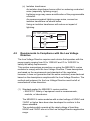
5. GENERAL SAFETY REQUIREMENTS
When a programmable controller is powered on or off, proper output of
the control target may not function temporarily due to delay and startup
time differences between the power supply for the programmable
controller and the external power supply for the control target
(especially in the case of DC). Also, an abnormal operation may occur if
an external power supply or the programmable controller fails.
From the point of view of fail-safe circuit and to prevent any of these
abnormal operations from leading to a total network system failure,
configure external fail-safe circuits (an emergency stop circuit,
protection circuit, and interlock circuit) in the areas where incorrect
operation can result in mechanical damage or accidents.
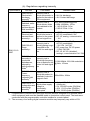
(1)
Fail-safe measures against failure of head module
The self-diagnostic function can detect failure of the head module.
However, if an error occurs in an area such as I/O control part, the
head module may not detect failure.
In this case, all points may turn on or off depending on the failure,
and normal operation and safety cannot be ensured.
Although Mitsubishi programmable controllers are manufactured
under strict quality control, it is recommended to configure external
fail-safe circuits to prevent mechanical damage or accidents due to
failure of the programmable controller.
24
WARRANTY
Please confirm the following product warranty details before using this product.
1. Gratis Warranty Term and Gratis Warranty Range
If any faults or defects (hereinafter "Failure") found to be the responsibility of
Mitsubishi occurs during use of the product within the gratis warranty term,
the product shall be repaired at no cost via the sales representative or
Mitsubishi Service Company.
However, if repairs are required onsite at domestic or overseas location,
expenses to send an engineer will be solely at the customer's discretion.
Mitsubishi shall not be held responsible for any re-commissioning,
maintenance, or testing on-site that involves replacement of the failed
module.
[Gratis Warranty Term]
The gratis warranty term of the product shall be for one year after the date of
purchase or delivery to a designated place.
Note that after manufacture and shipment from Mitsubishi, the maximum
distribution period shall be six (6) months, and the longest gratis warranty
term after manufacturing shall be eighteen (18) months. The gratis warranty
term of repair parts shall not exceed the gratis warranty term before repairs.
[Gratis Warranty Range]
(1)The range shall be limited to normal use within the usage state, usage
methods and usage environment, etc., which follow the conditions and
precautions, etc., given in the instruction manual, user's manual and
caution labels on the product.
(2)Even within the gratis warranty term, repairs shall be charged for in the
following cases.
1.Failure occurring from inappropriate storage or handling, carelessness
or negligence by the user. Failure caused by the user's hardware or
software design.
2.Failure caused by unapproved modifications, etc., to the product by the
user.
3.When the Mitsubishi product is assembled into a user's device, Failure
that could have been avoided if functions or structures, judged as
necessary in the legal safety measures the user's device is subject to or
as necessary by industry standards, had been provided.
4.Failure that could have been avoided if consumable parts (battery,
backlight, fuse, etc.) designated in the instruction manual had been
correctly serviced or replaced.
5.Failure caused by external irresistible forces such as fires or abnormal
voltages, and Failure caused by force majeure such as earthquakes,
lightning, wind and water damage.
6.Failure caused by reasons unpredictable by scientific technology
standards at time of shipment from Mitsubishi.
7.Any other failure found not to be the responsibility of Mitsubishi or that
admitted not to be so by the user.
25
2. Onerous repair term after discontinuation of production
(1)Mitsubishi shall accept onerous product repairs for seven (7) years after
production of the product is discontinued.
Discontinuation of production shall be notified with Mitsubishi Technical
Bulletins, etc.
(2)Product supply (including repair parts) is not available after production is
discontinued.
3. Overseas service
Overseas, repairs shall be accepted by Mitsubishi's local overseas FA
Center. Note that the repair conditions at each FA Center may differ.
4. Exclusion of loss in opportunity and secondary loss from warranty
liability
Regardless of the gratis warranty term, Mitsubishi shall not be liable for
compensation of damages caused by any cause found not to be the
responsibility of Mitsubishi, loss in opportunity, lost profits incurred to the user
by Failures of Mitsubishi products, special damages and secondary damages
whether foreseeable or not, compensation for accidents, and compensation
for damages to products other than Mitsubishi products, replacement by the
user, maintenance of on-site equipment, start-up test run and other tasks.
5. Changes in product specifications
The specifications given in the catalogs, manuals or technical documents are
subject to change without prior notice.
26
Revisions
* The manual number is given on the bottom right of the cover.
Print Date
January 2013
May 2013
May 2014
*Manual Number
IB(NA)-0800494-A
IB(NA)-0800494-B
IB(NA)-0800494-C
Revision
First edition
The description of L63SP is added.
Addition of descriptions of cUL.
This manual confers no industrial property rights or any rights of any other kind, nor does it
confer any patent licenses. Mitsubishi Electric Corporation cannot be held responsible for any
problems involving industrial property rights which may occur as a result of using the contents
noted in this manual.
©2013 MITSUBISHI ELECTRIC CORPORATION
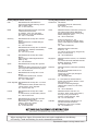
27
Country/Region Sales office/Tel
Country/Region Sales office/Tel
USA
Mitsubishi Electric Automation lnc.
500 Corporate Woods Parkway, Vernon
Hills, IL 60061, USA
Tel : +1-847-478-2100
South Africa
CBI-Electric.
Private Bag 2016, ZA-1600 Isando,
South Africa
Tel : +27-11-977-0770
Brazil
MELCO-TEC Representacao Comercial
e Assessoria Tecnica Ltda.
Av. Paulista, 1439, cj74, Bela Vista,
Sao Paulo CEP: 01311-200-SP Brazil
Tel : +55-11-3146-2200
China
Mitsubishi Electric Automation (China) Ltd.
No.1386 Hongqiao Road, Mitsubishi
Electric Automation Center, Changning
District, Shanghai, China
Tel : +86-21-2322-3030
Germany
Mitsubishi Electric Europe B.V. German
Branch
Gothaer Strasse 8, D-40880 Ratingen,
Germany
Tel : +49-2102-486-0
Taiwan
Setsuyo Enterprise Co., Ltd.
6F., No.105, Wugong 3rd Road, Wugu
District, New Taipei City 24889, Taiwan,
R.O.C.
Tel : +886-2-2299-2499
UK
Mitsubishi Electric Europe B.V. UK Branch
Travellers Lane, Hatfield, Hertfordshire,
AL10 8XB, UK.
Tel : +44-1707-27-6100
Korea
Italy
Mitsubishi Electric Europe B.V. Italian
Branch
Viale Colleoni 7-20864 Agrate Brianza
(Milano), Italy
Tel : +39-039-60531
Mitsubishi Electric Automation
Korea Co., Ltd.
3F, 1480-6, Gayang-Dong, Gangseo-Gu,
Seoul, 157-200, Korea
Tel : +82-2-3660-9530
Singapore
Mitsubishi Electric Europe B.V. Spanish
Branch
Carretera de Rubi 76-80.AC.420, E-08190
Sant Cugat del Valles (Barcelona), Spain
Tel : +34-93-565-3131
Mitsubishi Electric Asia Pte, Ltd. Industrial
Division
307, Alexandra Road, Mitsubishi Electric
Building, Singapore, 159943
Tel : +65-6470-2308
Thailand
Mitsubishi Electric Automation (Thailand)
Co., Ltd.
Bang-Chan Industrial Estate No.111
Soi Serithai 54,
T.Kannayao, A.Kannayao, Bangkok
10230 Thailand
Tel : +66-2906-3238
Indonesia
P. T. Autoteknindo Sumber Makmur
Muara Karang Selatan, Block A / Utara
No.1 Kav. No. 11,
Kawasan Industri Pergudangan,
Jakarta-Utara 14440, P.O, Box 5045,
Indonesia
Tel : +62-21-663-0833
India
Mitsubishi Electric India Pvt. Ltd.
2nd Floor, Tower A & B, Cyber Greens,
DLF Cyber City, DLF Phase-III,
Gurgaon-122002 Haryana, India
Tel : +91-124-463-0300
Australia
Mitsubishi Electric Australia Pty. Ltd.
348 Victoria Road PO BOX11,
Rydalmere, N.S.W 2116, Australia
Tel : +61-2-9684-7777
Spain
France
Mitsubishi Electric Europe B.V. French
Branch
25, Boulevard des Bouvets, F-92741
Nanterre Cedex, France
Tel : +33-1-5568-5568
Czech Republic Mitsubishi Electric Europe B.V.-o.s.Czech
office
Avenir Business Park, Radicka 751/113e,
158 00 Praha5, Czech Republic
Tel : +420-251-551-470
Poland
Mitsubishi Electric Europe B.V. Polish
Branch
ul. Krakowska 50, 32-083 Balice, Poland
Tel : +48-12-630-47-00
Russia
Mitsubishi Electric Europe B.V. Russian
Branch St.Petersburg office
Piskarevsky pr. 2, bld 2, lit "Sch", BC
"Benua", office 720; 195027,
St. Petersburg, Russia
Tel : +7-812-633-3497
HEAD OFFICE : TOKYO BUILDING, 2-7-3 MARUNOUCHI, CHIYODA-KU, TOKYO 100-8310, JAPAN
NAGOYA WORKS : 1-14, YADA-MINAMI 5-CHOME, HIGASHI-KU, NAGOYA, JAPAN
When exported from Japan, this manual does not require application to the Ministry
of Economy, Trade and Industry for service transaction permission.
Specifications subject to change without notice.