1
Cat. No. W343-E1-07
SYSMAC
CS/CJ Series
CS1W-ETN01 (10Base-5)
CS1W-ETN11 (10Base-T)
CJ1W-ETN11 (10Base-T)
Ethernet Units
OPERATION MANUAL
CS1W-ETN01 (10Base-5)
CS1W-ETN11 (10Base-T)
CJ1W-ETN11 (10Base-T)
Ethernet Units
Operation Manual
Revised January 2008
iv
Notice:
OMRON products are manufactured for use according to proper procedures by a qualified operator
and only for the purposes described in this manual.
The following conventions are used to indicate and classify precautions in this manual. Always heed
the information provided with them. Failure to heed precautions can result in injury to people or damage to property.
!DANGER
Indicates an imminently hazardous situation which, if not avoided, will result in death or
serious injury. Additionally, there may be severe property damage.
!WARNING
Indicates a potentially hazardous situation which, if not avoided, could result in death or
serious injury. Additionally, there may be severe property damage.
!Caution
Indicates a potentially hazardous situation which, if not avoided, may result in minor or
moderate injury, or property damage.
OMRON Product References
All OMRON products are capitalized in this manual. The word “Unit” is also capitalized when it refers to
an OMRON product, regardless of whether or not it appears in the proper name of the product.
The abbreviation “Ch,” which appears in some displays and on some OMRON products, often means
“word” and is abbreviated “Wd” in documentation in this sense.
The abbreviation “PC” means Programmable Controller and is not used as an abbreviation for anything
else.
Visual Aids
The following headings appear in the left column of the manual to help you locate different types of
information.
Note Indicates information of particular interest for efficient and convenient operation of the product.
1,2,3...
1. Indicates lists of one sort or another, such as procedures, checklists, etc.
OMRON, 2000
All rights reserved. No part of this publication may be reproduced, stored in a retrieval system, or transmitted, in any form, or
by any means, mechanical, electronic, photocopying, recording, or otherwise, without the prior written permission of
OMRON.
No patent liability is assumed with respect to the use of the information contained herein. Moreover, because OMRON is constantly striving to improve its high-quality products, the information contained in this manual is subject to change without
notice. Every precaution has been taken in the preparation of this manual. Nevertheless, OMRON assumes no responsibility
for errors or omissions. Neither is any liability assumed for damages resulting from the use of the information contained in
this publication.
v
vi
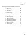
TABLE OF CONTENTS
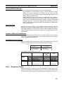
PRECAUTIONS . . . . . . . . . . . . . . . . . . . . . . . . . . . . . . . .
xvii
1
Intended Audience . . . . . . . . . . . . . . . . . . . . . . . . . . . . . . . . . . . . . . . . . . . . . . . . .
xviii
2
General Precautions . . . . . . . . . . . . . . . . . . . . . . . . . . . . . . . . . . . . . . . . . . . . . . . .
xviii
3
Safety Precautions. . . . . . . . . . . . . . . . . . . . . . . . . . . . . . . . . . . . . . . . . . . . . . . . . .
xviii
4
Operating Environment Precautions . . . . . . . . . . . . . . . . . . . . . . . . . . . . . . . . . . . .
xix
5
Application Precautions . . . . . . . . . . . . . . . . . . . . . . . . . . . . . . . . . . . . . . . . . . . . .
xix
6
Conformance to EC Directives . . . . . . . . . . . . . . . . . . . . . . . . . . . . . . . . . . . . . . . .
xxi
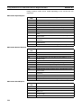
SECTION 1
Features and System Configuration . . . . . . . . . . . . . . . .
1
1-1
Features . . . . . . . . . . . . . . . . . . . . . . . . . . . . . . . . . . . . . . . . . . . . . . . . . . . . . . . . . .
2
1-2
System Configuration . . . . . . . . . . . . . . . . . . . . . . . . . . . . . . . . . . . . . . . . . . . . . . .
3
1-3
Devices Required in a Network . . . . . . . . . . . . . . . . . . . . . . . . . . . . . . . . . . . . . . .
4
1-4
Related Programming Devices . . . . . . . . . . . . . . . . . . . . . . . . . . . . . . . . . . . . . . . .
6
1-5
Specifications . . . . . . . . . . . . . . . . . . . . . . . . . . . . . . . . . . . . . . . . . . . . . . . . . . . . .
7
1-6
Software Configuration . . . . . . . . . . . . . . . . . . . . . . . . . . . . . . . . . . . . . . . . . . . . . .
10
1-7
IP Addresses . . . . . . . . . . . . . . . . . . . . . . . . . . . . . . . . . . . . . . . . . . . . . . . . . . . . . .
12
1-8
Precautions . . . . . . . . . . . . . . . . . . . . . . . . . . . . . . . . . . . . . . . . . . . . . . . . . . . . . . .
14
SECTION 2
Communications Functions . . . . . . . . . . . . . . . . . . . . . . .
15
2-1
Communications Functions. . . . . . . . . . . . . . . . . . . . . . . . . . . . . . . . . . . . . . . . . . .
16
2-2
FINS Communications . . . . . . . . . . . . . . . . . . . . . . . . . . . . . . . . . . . . . . . . . . . . . .
18
2-3
Socket Services . . . . . . . . . . . . . . . . . . . . . . . . . . . . . . . . . . . . . . . . . . . . . . . . . . . .
19
2-4
FTP Server . . . . . . . . . . . . . . . . . . . . . . . . . . . . . . . . . . . . . . . . . . . . . . . . . . . . . . .
21
2-5
Mail . . . . . . . . . . . . . . . . . . . . . . . . . . . . . . . . . . . . . . . . . . . . . . . . . . . . . . . . . . . . .
21
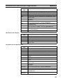
SECTION 3
Installation and Initial Setup . . . . . . . . . . . . . . . . . . . . . .
23
3-1
Before Operation. . . . . . . . . . . . . . . . . . . . . . . . . . . . . . . . . . . . . . . . . . . . . . . . . . .
24
3-2
Overview of Startup Procedure . . . . . . . . . . . . . . . . . . . . . . . . . . . . . . . . . . . . . . . .
26
3-3
Unit Components . . . . . . . . . . . . . . . . . . . . . . . . . . . . . . . . . . . . . . . . . . . . . . . . . .
28
3-4
Switch Settings . . . . . . . . . . . . . . . . . . . . . . . . . . . . . . . . . . . . . . . . . . . . . . . . . . . .
33
3-5
Mounting to a PC . . . . . . . . . . . . . . . . . . . . . . . . . . . . . . . . . . . . . . . . . . . . . . . . . .
37
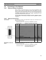
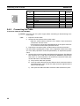
3-6
Connecting to the Network . . . . . . . . . . . . . . . . . . . . . . . . . . . . . . . . . . . . . . . . . . .
39
3-7
Creating an I/O Table . . . . . . . . . . . . . . . . . . . . . . . . . . . . . . . . . . . . . . . . . . . . . . .
45
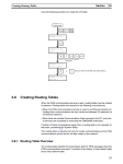
3-8
Creating Routing Tables . . . . . . . . . . . . . . . . . . . . . . . . . . . . . . . . . . . . . . . . . . . . .
46
3-9
System Setup. . . . . . . . . . . . . . . . . . . . . . . . . . . . . . . . . . . . . . . . . . . . . . . . . . . . . .
51
3-10 Creating an IP Address Table . . . . . . . . . . . . . . . . . . . . . . . . . . . . . . . . . . . . . . . . .
52
3-11 Creating an IP Router Table . . . . . . . . . . . . . . . . . . . . . . . . . . . . . . . . . . . . . . . . . .
52
3-12 Checking Communications . . . . . . . . . . . . . . . . . . . . . . . . . . . . . . . . . . . . . . . . . . .
53
vii
TABLE OF CONTENTS
SECTION 4
System Setup and Memory Allocations. . . . . . . . . . . . . .
57
4-1
Allocated Words . . . . . . . . . . . . . . . . . . . . . . . . . . . . . . . . . . . . . . . . . . . . . . . . . .
58
4-2
CPU Bus Unit System Setup . . . . . . . . . . . . . . . . . . . . . . . . . . . . . . . . . . . . . . . . .
59
4-3
CIO Area Allocations . . . . . . . . . . . . . . . . . . . . . . . . . . . . . . . . . . . . . . . . . . . . . .
67
4-4
DM Area Allocations. . . . . . . . . . . . . . . . . . . . . . . . . . . . . . . . . . . . . . . . . . . . . . .
73
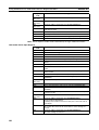
SECTION 5
FINS Communications . . . . . . . . . . . . . . . . . . . . . . . . . . .
79
5-1
Overview of FINS Communications . . . . . . . . . . . . . . . . . . . . . . . . . . . . . . . . . . .
80
5-2
Procedure Before Using FINS Communications. . . . . . . . . . . . . . . . . . . . . . . . . .
82
5-3
Sending Commands From a PC. . . . . . . . . . . . . . . . . . . . . . . . . . . . . . . . . . . . . . .
83
5-4
Sending Commands From a Host Computer . . . . . . . . . . . . . . . . . . . . . . . . . . . . .
96
5-5
FINS Server . . . . . . . . . . . . . . . . . . . . . . . . . . . . . . . . . . . . . . . . . . . . . . . . . . . . . .
102
SECTION 6
Socket Services. . . . . . . . . . . . . . . . . . . . . . . . . . . . . . . . . .
103
6-1
Overview . . . . . . . . . . . . . . . . . . . . . . . . . . . . . . . . . . . . . . . . . . . . . . . . . . . . . . . .
104
6-2
Using Socket Services with Socket Service Request Switches . . . . . . . . . . . . . . .
112
6-3
Using Socket Services with CMND(490) . . . . . . . . . . . . . . . . . . . . . . . . . . . . . . .
139
SECTION 7
FTP Server . . . . . . . . . . . . . . . . . . . . . . . . . . . . . . . . . . . . .
161
7-1
Overview . . . . . . . . . . . . . . . . . . . . . . . . . . . . . . . . . . . . . . . . . . . . . . . . . . . . . . . .
162
7-2
Setting Login Names and Passwords. . . . . . . . . . . . . . . . . . . . . . . . . . . . . . . . . . .
163
7-3
Using File Memory . . . . . . . . . . . . . . . . . . . . . . . . . . . . . . . . . . . . . . . . . . . . . . . .
163
7-4
FTP Server Application Example . . . . . . . . . . . . . . . . . . . . . . . . . . . . . . . . . . . . .
167
7-5
Using FTP Commands. . . . . . . . . . . . . . . . . . . . . . . . . . . . . . . . . . . . . . . . . . . . . .
168
7-6
UNIX Application Example . . . . . . . . . . . . . . . . . . . . . . . . . . . . . . . . . . . . . . . . .
174
SECTION 8
Mail . . . . . . . . . . . . . . . . . . . . . . . . . . . . . . . . . . . . . . . . . . .
177
8-1
Overview of Mail Function . . . . . . . . . . . . . . . . . . . . . . . . . . . . . . . . . . . . . . . . . .
178
8-2
Sending Mail . . . . . . . . . . . . . . . . . . . . . . . . . . . . . . . . . . . . . . . . . . . . . . . . . . . . .
182
8-3
Mail Example. . . . . . . . . . . . . . . . . . . . . . . . . . . . . . . . . . . . . . . . . . . . . . . . . . . . .
182
SECTION 9
Testing Communications . . . . . . . . . . . . . . . . . . . . . . . . .
185
viii
9-1
Communications Testing Functions . . . . . . . . . . . . . . . . . . . . . . . . . . . . . . . . . . .
186
9-2
PING Command . . . . . . . . . . . . . . . . . . . . . . . . . . . . . . . . . . . . . . . . . . . . . . . . . .
186
9-3
Internode Test . . . . . . . . . . . . . . . . . . . . . . . . . . . . . . . . . . . . . . . . . . . . . . . . . . . .
187
TABLE OF CONTENTS
SECTION 10
Troubleshooting . . . . . . . . . . . . . . . . . . . . . . . . . . . . . . . .
191
10-1 Troubleshooting with Indicators . . . . . . . . . . . . . . . . . . . . . . . . . . . . . . . . . . . . . . .
192
10-2 Error Status . . . . . . . . . . . . . . . . . . . . . . . . . . . . . . . . . . . . . . . . . . . . . . . . . . . . . . .
194
10-3 Error Log. . . . . . . . . . . . . . . . . . . . . . . . . . . . . . . . . . . . . . . . . . . . . . . . . . . . . . . . .
194
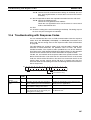
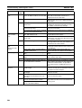
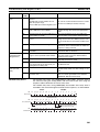
10-4 Error Log Error Codes . . . . . . . . . . . . . . . . . . . . . . . . . . . . . . . . . . . . . . . . . . . . . .
195
10-5 Troubleshooting Procedures . . . . . . . . . . . . . . . . . . . . . . . . . . . . . . . . . . . . . . . . . .
197
10-6 Troubleshooting with Response Codes . . . . . . . . . . . . . . . . . . . . . . . . . . . . . . . . . .
207
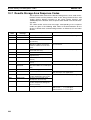
10-7 Results Storage Area Response Codes . . . . . . . . . . . . . . . . . . . . . . . . . . . . . . . . . .
210
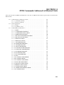
SECTION 11
FINS Commands Addressed to Ethernet Units . . . . . . .
213
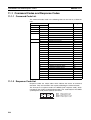
11-1 Command Codes and Response Codes . . . . . . . . . . . . . . . . . . . . . . . . . . . . . . . . . .
214
11-2 Socket Applications . . . . . . . . . . . . . . . . . . . . . . . . . . . . . . . . . . . . . . . . . . . . . . . .
215
11-3 Command/Response Reference . . . . . . . . . . . . . . . . . . . . . . . . . . . . . . . . . . . . . . .
217
Appendices
A
Network Installation . . . . . . . . . . . . . . . . . . . . . . . . . . . . . . . . . . . . . . . . . . . . . . . .
251
B
Ethernet Network Parameters . . . . . . . . . . . . . . . . . . . . . . . . . . . . . . . . . . . . . . . .
261
C
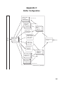
Buffer Configuration . . . . . . . . . . . . . . . . . . . . . . . . . . . . . . . . . . . . . . . . . . . . . . .
263
D
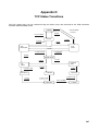
TCP Status Transitions . . . . . . . . . . . . . . . . . . . . . . . . . . . . . . . . . . . . . . . . . . . . . .
265
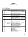
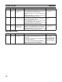
E
Auxiliary Area Data . . . . . . . . . . . . . . . . . . . . . . . . . . . . . . . . . . . . . . . . . . . . . . . .
267
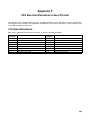
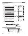
F
CPU Bus Unit Allocations in the CPU Unit . . . . . . . . . . . . . . . . . . . . . . . . . . . . .
269
G
ASCII Characters . . . . . . . . . . . . . . . . . . . . . . . . . . . . . . . . . . . . . . . . . . . . . . . . . .
277
H
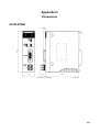
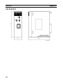
Dimensions . . . . . . . . . . . . . . . . . . . . . . . . . . . . . . . . . . . . . . . . . . . . . . . . . . . . . . .
279
I
Maintenance . . . . . . . . . . . . . . . . . . . . . . . . . . . . . . . . . . . . . . . . . . . . . . . . . . . . . .
283
J
Inspections . . . . . . . . . . . . . . . . . . . . . . . . . . . . . . . . . . . . . . . . . . . . . . . . . . . . . . .
285
Index. . . . . . . . . . . . . . . . . . . . . . . . . . . . . . . . . . . . . . . . . .
287
Revision History . . . . . . . . . . . . . . . . . . . . . . . . . . . . . . . .
293
ix
About this Manual:
This manual describes the installation and operation of the SYSMAC CS-series CS1W-ETN01
(10Base-5) and CS1W-ETN11 (10Base-T) Ethernet Units and the CJ-series CJ1W-ETN11 (10Base-T)
Ethernet Unit, and includes the sections described on the next page.
An Ethernet Unit is classified and treated as a CPU Bus Unit in PC processing.
This manual is based on Ethernet* networks comprised of Ethernet Unit nodes and UNIX* host computer nodes. Although details can vary, theoretically any device supporting the same Ethernet protocols as the Ethernet Unit can form nodes on the network.
Note
*Ethernet is a trademark of the Xerox Corporation. UNIX is a registered trademark of USL.
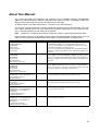
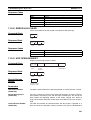
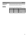
Please read this manual and all related manuals listed in the following table carefully and be sure you
understand the information provided before attempting to install and operate an Ethernet Unit.
Name
Cat. No.
Contents
SYSMAC CS/CJ-series
CS1W-ETN01/ETN11
CJ1W-ETN11
Ethernet Units
Operation Manual
(this manual)
W343-E1-@
Describes the installation and operation of the CS1W-ETN01 (10Base5), CS1W-ETN11 (10Base-T), and CJ1W-ETN11 Ethernet Units.
Refer to the CX-Programmer User’s Manual for information on setting
the CPU Bus Unit Setup for the Ethernet Unit.
Refer to the Communications Commands Reference Manual (W342) for
information on FINS commands that can be addressed to CS/CJ-series
CPU Units.
SYSMAC CS/CJ-series
CS1W-ETN21
CJ1W-ETN21
Ethernet Units
Operation Manual
(Construction of Networks)
W420-E1-@
Describes the basic settings and FINS communications for the CS1WETN21 (100Base-TX) and CJ1W-ETN21 (100Base-TX) Ethernet Units.
Refer to the Communications Commands Reference Manual (W342) for
information on FINS commands that can be addressed to CS/CJ-series
CPU Units.
SYSMAC CS/CJ-series
CS1W-ETN21
CJ1W-ETN21
Ethernet Units
Operation Manual
(Construction of Applications)
W421-E1-@
Provides information for the CS1W-ETN21 (100Base-TX) and CJ1WETN21 (100Base-TX) Ethernet Units on functions such as mail transmission, socket services, automatic clock adjustment, FTP server, and
creating host applications with FINS communications.
SYSMAC CS-series
CS1G/H-CPU@@-EV1, CS1G/H-CPU@@H
Programmable Controllers
Operation Manual
W339-E1-@
Provides an outline of and describes the design, installation, maintenance, and other basic operations for the CS-series PCs.
SYSMAC CJ-series
CJ1G-CPU@@
Programmable Controllers
Operation Manual
W393-E1-@
Provides an outline of and describes the design, installation, maintenance, and other basic operations for the CJ-series PCs.
W394-E1-@
SYSMAC CS/CJ-series
CS1G/H-CPU@@-EV1, CS1G/H-CPU@@H,
CJ1G/H-CPU@@H, CJ1M-CPU@@,
CJ1G-CPU@@
Programmable Controllers
Programming Manual
This manual describes programming and other methods to use the functions of the CS/CJ-series PCs.
SYSMAC CS/CJ-series
W340-E1-@
CS1G/H-CPU@@-EV1, CS1G/H-CPU@@H,
CJ1G/H-CPU@@H, CJ1M-CPU@@,
CJ1G-CPU@@
Programmable Controllers
Instructions Reference Manual
Describes the ladder diagram programming instructions supported by
CS-series and CJ-series PCs.
xi
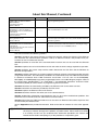
About this Manual, Continued
Name
Cat. No.
Contents
SYSMAC CS/CJ-series
C200H-PRO27-E, CQM1H-PRO01-E
CQM1-PRO01-E
Programming Consoles
Operation Manual
W341-E1-@
Provides information on how to program and operate CS/CJ-series PCs
using a Programming Console.
SYSMAC CS/CJ-series
CS1G/H-CPU@@-EV1, CJ1G-CPU@@,
CS1W-SCB21-V1/41-V1, CS1W-SCU21,
CJ1W-SCU41
Communications Commands
Reference Manual
W342-E1-@
Describes the C-series (Host Link) and FINS communications commands used with CS/CJ-series PCs.
SYSMAC WS02-CXPC1-EV3
CX-Programmer Ver. 3.1
Operation Manual
W414-E1-@
Provide information on how to use the CX-Programmer, a programming
device that supports the CS/CJ-series PCs, and the CX-Net contained
within CX-Programmer.
SYSMAC CS/CJ-series
CS1W-SCB21-V1/41-V1, CS1W-SCU21
CJ1W-CSU41
Serial Communications Boards and Serial
Communications Units
Operation Manual
W336-E1-@
Describes the use of Serial Communications Units and Boards to perform serial communications with external devices, including the usage
of standard system protocols for OMRON products.
This manual contains the following sections.
Section 1 introduces the overall structure of an Ethernet network, outlines the features of the Ethernet
Unit, describes the communications protocols used by an Ethernet network, and provides basic precautions for use of an Ethernet network.
Section 2 provides an overview of the communications functions that can be used with the Ethernet
Unit.
Section 3 explains how to install the Ethernet Unit and make the initial settings required for operation.
Section 4 explains the system setup and the words allocated in the CIO Area and the DM Area for
Ethernet Unit operations.
Section 5 provides information on communicating on Ethernet networks and interconnected networks
using FINS commands. The information provided in the section deals only with FINS communications
in reference to Ethernet Units. FINS commands issued from a PC are sent via the SEND(090),
RECV(098), and CMND(490) instructions programmed into the user ladder-diagram program. Refer to
the CS/CJ-series CS1G/H-CPU@@-E, CJ1G-CPU@@ Programmable Controllers Instruction Reference Manual (W340) for further details on programming these instructions.
Section 6 describes the functionality provided by the Ethernet Unit via the socket services.
Section 7 describes the functions provided by the FTP server.
Section 8 explains the Ethernet Unit’s mail function.
Section 9 describes functions that allow you to test communications.
Section 10 describes information and procedures that can be used to troubleshoot problems that
sometimes occur with Ethernet Unit and Ethernet communications.
Section 11 describes the FINS commands that can be sent to an Ethernet Unit and the responses that
are returned by the Ethernet Unit.
Various Appendices are provided for reference. Refer to the table of contents for a list of the appendices.
!WARNING Failure to read and understand the information provided in this manual may result in personal injury or death, damage to the product, or product failure. Please read each section
in its entirety and be sure you understand the information provided in the section and
related sections before attempting any of the procedures or operations given.
xii
Read and Understand this Manual
Please read and understand this manual before using the product. Please consult your OMRON
representative if you have any questions or comments.
Warranty and Limitations of Liability
WARRANTY
OMRON's exclusive warranty is that the products are free from defects in materials and workmanship for a
period of one year (or other period if specified) from date of sale by OMRON.
OMRON MAKES NO WARRANTY OR REPRESENTATION, EXPRESS OR IMPLIED, REGARDING NONINFRINGEMENT, MERCHANTABILITY, OR FITNESS FOR PARTICULAR PURPOSE OF THE
PRODUCTS. ANY BUYER OR USER ACKNOWLEDGES THAT THE BUYER OR USER ALONE HAS
DETERMINED THAT THE PRODUCTS WILL SUITABLY MEET THE REQUIREMENTS OF THEIR
INTENDED USE. OMRON DISCLAIMS ALL OTHER WARRANTIES, EXPRESS OR IMPLIED.
LIMITATIONS OF LIABILITY
OMRON SHALL NOT BE RESPONSIBLE FOR SPECIAL, INDIRECT, OR CONSEQUENTIAL DAMAGES,
LOSS OF PROFITS OR COMMERCIAL LOSS IN ANY WAY CONNECTED WITH THE PRODUCTS,
WHETHER SUCH CLAIM IS BASED ON CONTRACT, WARRANTY, NEGLIGENCE, OR STRICT
LIABILITY.
In no event shall the responsibility of OMRON for any act exceed the individual price of the product on which
liability is asserted.
IN NO EVENT SHALL OMRON BE RESPONSIBLE FOR WARRANTY, REPAIR, OR OTHER CLAIMS
REGARDING THE PRODUCTS UNLESS OMRON'S ANALYSIS CONFIRMS THAT THE PRODUCTS
WERE PROPERLY HANDLED, STORED, INSTALLED, AND MAINTAINED AND NOT SUBJECT TO
CONTAMINATION, ABUSE, MISUSE, OR INAPPROPRIATE MODIFICATION OR REPAIR.
xiii
Application Considerations
SUITABILITY FOR USE
OMRON shall not be responsible for conformity with any standards, codes, or regulations that apply to the
combination of products in the customer's application or use of the products.
At the customer's request, OMRON will provide applicable third party certification documents identifying
ratings and limitations of use that apply to the products. This information by itself is not sufficient for a
complete determination of the suitability of the products in combination with the end product, machine,
system, or other application or use.
The following are some examples of applications for which particular attention must be given. This is not
intended to be an exhaustive list of all possible uses of the products, nor is it intended to imply that the uses
listed may be suitable for the products:
• Outdoor use, uses involving potential chemical contamination or electrical interference, or conditions or
uses not described in this manual.
• Nuclear energy control systems, combustion systems, railroad systems, aviation systems, medical
equipment, amusement machines, vehicles, safety equipment, and installations subject to separate
industry or government regulations.
• Systems, machines, and equipment that could present a risk to life or property.
Please know and observe all prohibitions of use applicable to the products.
NEVER USE THE PRODUCTS FOR AN APPLICATION INVOLVING SERIOUS RISK TO LIFE OR
PROPERTY WITHOUT ENSURING THAT THE SYSTEM AS A WHOLE HAS BEEN DESIGNED TO
ADDRESS THE RISKS, AND THAT THE OMRON PRODUCTS ARE PROPERLY RATED AND
INSTALLED FOR THE INTENDED USE WITHIN THE OVERALL EQUIPMENT OR SYSTEM.
PROGRAMMABLE PRODUCTS
OMRON shall not be responsible for the user's programming of a programmable product, or any
consequence thereof.
xiv
Disclaimers
CHANGE IN SPECIFICATIONS
Product specifications and accessories may be changed at any time based on improvements and other
reasons.
It is our practice to change model numbers when published ratings or features are changed, or when
significant construction changes are made. However, some specifications of the products may be changed
without any notice. When in doubt, special model numbers may be assigned to fix or establish key
specifications for your application on your request. Please consult with your OMRON representative at any
time to confirm actual specifications of purchased products.
DIMENSIONS AND WEIGHTS
Dimensions and weights are nominal and are not to be used for manufacturing purposes, even when
tolerances are shown.
PERFORMANCE DATA
Performance data given in this manual is provided as a guide for the user in determining suitability and does
not constitute a warranty. It may represent the result of OMRON's test conditions, and the users must
correlate it to actual application requirements. Actual performance is subject to the OMRON Warranty and
Limitations of Liability.
ERRORS AND OMISSIONS
The information in this manual has been carefully checked and is believed to be accurate; however, no
responsibility is assumed for clerical, typographical, or proofreading errors, or omissions.
xv
xvi
PRECAUTIONS
This section provides general precautions for using the CS/CJ-series Programmable Controllers (PCs) and related devices.
The information contained in this section is important for the safe and reliable application of Programmable
Controllers. You must read this section and understand the information contained before attempting to set up or
operate a PC system.
1
2
3
4
5
6
Intended Audience . . . . . . . . . . . . . . . . . . . . . . . . . . . . . . . . . . . . . . . . . . . . .
General Precautions . . . . . . . . . . . . . . . . . . . . . . . . . . . . . . . . . . . . . . . . . . . .
Safety Precautions. . . . . . . . . . . . . . . . . . . . . . . . . . . . . . . . . . . . . . . . . . . . . .
Operating Environment Precautions . . . . . . . . . . . . . . . . . . . . . . . . . . . . . . . .
Application Precautions . . . . . . . . . . . . . . . . . . . . . . . . . . . . . . . . . . . . . . . . .
Conformance to EC Directives . . . . . . . . . . . . . . . . . . . . . . . . . . . . . . . . . . . .
xviii
xviii
xviii
xix
xix
xxi
xvii
1
Intended Audience
1
Intended Audience
This manual is intended for the following personnel, who must also have
knowledge of electrical systems (an electrical engineer or the equivalent).
• Personnel in charge of installing FA systems.
• Personnel in charge of designing FA systems.
• Personnel in charge of managing FA systems and facilities.
2
General Precautions
The user must operate the product according to the performance specifications described in the operation manuals.
Before using the product under conditions which are not described in the
manual or applying the product to nuclear control systems, railroad systems,
aviation systems, vehicles, combustion systems, medical equipment, amusement machines, safety equipment, and other systems, machines, and equipment that may have a serious influence on lives and property if used
improperly, consult your OMRON representative.
Make sure that the ratings and performance characteristics of the product are
sufficient for the systems, machines, and equipment, and be sure to provide
the systems, machines, and equipment with double safety mechanisms.
This manual provides information for programming and operating the Unit. Be
sure to read this manual before attempting to use the Unit and keep this manual close at hand for reference during operation.
!WARNING It is extremely important that a PC and all PC Units be used for the specified
purpose and under the specified conditions, especially in applications that can
directly or indirectly affect human life. You must consult with your OMRON
representative before applying a PC System to the above-mentioned applications.
3
Safety Precautions
!WARNING Do not attempt to take any Unit apart while the power is being supplied. Doing
so may result in electric shock.
!WARNING Do not touch any of the terminals or terminal blocks while the power is being
supplied. Doing so may result in electric shock.
!WARNING Do not attempt to disassemble, repair, or modify any Units. Any attempt to do
so may result in malfunction, fire, or electric shock.
!WARNING Do not touch the Power Supply Unit while power is being supplied or immediately after power has been turned OFF. Doing so may result in electric shock.
!Caution Tighten the screws on the terminal block of the AC Power Supply Unit to the
torque specified in the operation manual. The loose screws may result in
burning or malfunction.
xviii
Operating Environment Precautions
4
!Caution Execute online edit only after confirming that no adverse effects will be
caused by extending the cycle time. Otherwise, the input signals may not be
readable.
4
Operating Environment Precautions
!Caution Do not operate the control system in the following places:
• Locations subject to direct sunlight.
• Locations subject to temperatures or humidity outside the range specified
in the specifications.
• Locations subject to condensation as the result of severe changes in temperature.
• Locations subject to corrosive or flammable gases.
• Locations subject to dust (especially iron dust) or salts.
• Locations subject to exposure to water, oil, or chemicals.
• Locations subject to shock or vibration.
!Caution Take appropriate and sufficient countermeasures when installing systems in
the following locations:
• Locations subject to static electricity or other forms of noise.
• Locations subject to strong electromagnetic fields.
• Locations subject to possible exposure to radioactivity.
• Locations close to power supplies.
!Caution The operating environment of the PC System can have a large effect on the
longevity and reliability of the system. Improper operating environments can
lead to malfunction, failure, and other unforeseeable problems with the PC
System. Be sure that the operating environment is within the specified conditions at installation and remains within the specified conditions during the life
of the system. Follow all installation instructions and precautions provided in
the operation manuals.
5
Application Precautions
Observe the following precautions when using the PC System.
!WARNING Always heed these precautions. Failure to abide by the following precautions
could lead to serious or possibly fatal injury.
• Always connect to a ground of 100 Ω or less when installing the Units. Not
connecting to a ground to a ground of 100 Ω or less may result in electric
shock.
• A ground of 100 Ω or less must be installed when shorting the GR and LG
terminals on the Power Supply Unit.
• Always turn OFF the power supply to the PC before attempting any of the
following. Not turning OFF the power supply may result in malfunction or
electric shock.
xix
5
Application Precautions
• Mounting or dismounting I/O Units, CPU Units, Inner Boards, or any
other Units.
• Assembling the Units.
• Setting DIP switches or rotary switches.
• Connecting cables or wiring the system.
!Caution Failure to abide by the following precautions could lead to faulty operation of
the PC or the system, or could damage the PC or PC Units. Always heed
these precautions.
• Fail-safe measures must be taken by the customer to ensure safety in the
event of incorrect, missing, or abnormal signals caused by broken signal
lines, momentary power interruptions, or other causes.
• Interlock circuits, limit circuits, and similar safety measures in external circuits (i.e., not in the Programmable Controller) must be provided by the
customer.
• Always use the power supply voltages specified in the operation manuals.
An incorrect voltage may result in malfunction or burning.
• Take appropriate measures to ensure that the specified power with the
rated voltage and frequency is supplied. Be particularly careful in places
where the power supply is unstable. An incorrect power supply may result
in malfunction.
• Install external breakers and take other safety measures against short-circuiting in external wiring. Insufficient safety measures against short-circuiting may result in burning.
• Be sure that all the mounting screws, terminal screws, and cable connector screws are tightened to the torque specified in the relevant manuals.
Incorrect tightening torque may result in malfunction.
• Leave the label attached to the Unit when wiring. Removing the label may
result in malfunction if foreign matter enters the Unit.
• Remove the label after the completion of wiring to ensure proper heat dissipation. Leaving the label attached may result in malfunction.
• Use crimp terminals for wiring. Do not connect bare stranded wires
directly to terminals. Connection of bare stranded wires may result in
burning.
• Wire all connections correctly.
• Double-check all wiring and switch settings before turning ON the power
supply. Incorrect wiring may result in burning.
• Mount Units only after checking terminal blocks and connectors completely.
• Be sure that the terminal blocks, Memory Units, expansion cables, and
other items with locking devices are properly locked into place. Improper
locking may result in malfunction.
• Check the user program for proper execution before actually running it on
the Unit. Not checking the program may result in an unexpected operation.
• Do not lay communications cables near power lines or high-voltage lines.
• Always lay communications cables in ducts.
xx
6
Conformance to EC Directives
• Do not pull on the communications cables or bend the communications
cables beyond their natural limit. Doing either of these may break the
cables.
• Do not place objects on top of the communications cables or other wiring
lines. Doing so may break the cables.
• Before touching a Unit, be sure to first touch a grounded metallic object in
order to discharge any static built-up. Not doing so may result in malfunction or damage.
• When transporting or storing Units, place them in special packing boxes
and do not allow them to be subject to excessive shock or vibration during
transportation.
• Confirm that no adverse effect will occur in the system before attempting
any of the following. Not doing so may result in an unexpected operation.
• Changing the operating mode of the PC.
• Force-setting/force-resetting any bit in memory.
• Changing the present value of any word or any set value in memory.
6
6-1
Conformance to EC Directives
Applicable Directives
• EMC Directives
• Low Voltage Directive
6-2
Concepts
EMC Directives
OMRON devices that comply with EC Directives also conform to the related
EMC standards so that they can be more easily built into other devices or the
overall machine. The actual products have been checked for conformity to
EMC standards (see the following note). Whether the products conform to the
standards in the system used by the customer, however, must be checked by
the customer.
EMC-related performance of the OMRON devices that comply with EC Directives will vary depending on the configuration, wiring, and other conditions of
the equipment or control panel on which the OMRON devices are installed.
The customer must, therefore, perform the final check to confirm that devices
and the overall machine conform to EMC standards.
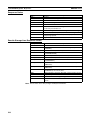
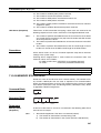
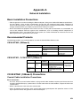
Note Conformance with the EMC (Electromagnetic Compatibility) standards for
EMS (Electromagnetic Susceptibility) and EMI (Electromagnetic Interference)
vary with the model in the way shown below.
Ethernet Unit
CS1W-ETN01/11
CJ1W-ETN11
EMS
EN61131-2
EN61000-6-2
EMI
EN61000-6-4 (Radiated emission: 10-m regulations)
Low Voltage Directive
Always ensure that devices operating at voltages of 50 to 1,000 VAC and 75
to 1,500 VDC meet the required safety standards for the PC (EN61131-2).
xxi
SECTION 1
Features and System Configuration
This section introduces the overall structure of an Ethernet network, outlines the features of the Ethernet Unit, describes
the communications protocols used by an Ethernet network, and provides basic precautions for use of an Ethernet network.
1-1
1-2
1-3
Features . . . . . . . . . . . . . . . . . . . . . . . . . . . . . . . . . . . . . . . . . . . . . . . . . . . . . .
2
System Configuration . . . . . . . . . . . . . . . . . . . . . . . . . . . . . . . . . . . . . . . . . . .
3
1-2-1
Device Configuration . . . . . . . . . . . . . . . . . . . . . . . . . . . . . . . . . . . .
3
1-2-2
Node Connections. . . . . . . . . . . . . . . . . . . . . . . . . . . . . . . . . . . . . . .
3
Devices Required in a Network . . . . . . . . . . . . . . . . . . . . . . . . . . . . . . . . . . .
4
1-3-1
10Base-5 Ethernet Unit. . . . . . . . . . . . . . . . . . . . . . . . . . . . . . . . . . .
4
1-3-2
10Base-T Ethernet Unit . . . . . . . . . . . . . . . . . . . . . . . . . . . . . . . . . .
5
1-4
Related Programming Devices . . . . . . . . . . . . . . . . . . . . . . . . . . . . . . . . . . . .
6
1-5
Specifications . . . . . . . . . . . . . . . . . . . . . . . . . . . . . . . . . . . . . . . . . . . . . . . . .
7
1-6
Software Configuration . . . . . . . . . . . . . . . . . . . . . . . . . . . . . . . . . . . . . . . . . .
10
1-7
IP Addresses . . . . . . . . . . . . . . . . . . . . . . . . . . . . . . . . . . . . . . . . . . . . . . . . . .
12
1-7-1
IP Address Configuration . . . . . . . . . . . . . . . . . . . . . . . . . . . . . . . . .
12
1-7-2
Allocating IP Addresses . . . . . . . . . . . . . . . . . . . . . . . . . . . . . . . . . .
12
1-8
1-7-3
IP Address Settings. . . . . . . . . . . . . . . . . . . . . . . . . . . . . . . . . . . . . .
13
1-7-4
Subnet Masks . . . . . . . . . . . . . . . . . . . . . . . . . . . . . . . . . . . . . . . . . .
13
Precautions . . . . . . . . . . . . . . . . . . . . . . . . . . . . . . . . . . . . . . . . . . . . . . . . . . .
14
1-8-1
Installation . . . . . . . . . . . . . . . . . . . . . . . . . . . . . . . . . . . . . . . . . . . .
14
1-8-2
Ethernet and IEEE802.3 Standards. . . . . . . . . . . . . . . . . . . . . . . . . .
14
1
Section 1-1
Features
1-1
Features
Select from 10Base-5 or
10Base-T
Three models of Ethernet Unit are provided to support both 10Base-5
(CS1W-ETN01) and 10Base-T (CS1W-ETN11/CJ1W-ETN11) Ethernet transmission media.
Wide-ranging Control
Capability Using Ethernet
The Ethernet Unit enables a Programmable Controller (PC) to support a wide
range of protocols via Ethernet, including data communications by TCP/IP
and UDP/IP socket services, FINS command execution (OMRON’s standard
protocol), FTP file transfers, and SMTP message communications.
Communications by UDP/
IP and TCP/IP
The Ethernet Unit supports the standard Ethernet protocols, UDP/IP and
TCP/IP, so it can communicate with other Ethernet devices, workstations, personal computers, and Ethernet Units produced by other manufacturers. It can
utilize up to eight socket ports for the various protocols, allowing it to be
employed in a wide range of applications.
Easy Use of Socket
Services
TCP or UDP socket services can be easily accessed either by executing the
CMND(490) instruction or by presetting parameters and then manipulating
dedicated control switches in memory. Presetting parameters eliminates the
need for ladder programs to monitor the completion timing of instructions and
socket service processing, and thereby reduces the work hours involved in
program development.
FINS Message
Communications
(FINS Communications
Service Using UDP/IP)
The Ethernet Unit also supports FINS message communications, OMRON’s
standard communications service, so other OMRON PCs can be accessed by
using SEND(090), RECV(098), and CMND(490) instructions in ladder programs. In addition, the FINS gateway function can be used to allow access to
other PCs on not only the same Ethernet network but also on other networks
such as Controller Link and SYSMAC Link.
File Transfers Between PC
and Host Computer
(FTP Server Function)
The Ethernet Unit has a built-in FTP server function, so any workstation or
personal computer with an FTP client function can be used for reading files
from or writing files to the PC. This enables large amounts of data to be transferred at one time without any need for writing a ladder program.
E-mail Capability
User-defined messages, Unit error information, status information, and so on,
can be sent from the PC to the mail server as e-mail. This function allows
information generated at the production site to be sent out as e-mail.
24-VDC Power Supply for
Transceiver
For the CS1W-ETN01 (10Base-5), a 24-VDC power supply can be used as
the power supply for the transceiver. The Ethernet Unit voltage output provides for a voltage drop in the transceiver cables, so there is no need to adjust
the power supply voltage.
Controller Link Network
Connection
Ethernet, the information-system network, can be connected to Controller
Link, the control-system network, using the FINS communications service.
This allows a PC on the Controller Link network to be monitored from a PC on
the Ethernet network, and, conversely, for data to be exchanged between a
PC on the Controller Link network and a PC on the Ethernet network.
Abundant
Troubleshooting
Functions
The Ethernet Unit is provided with a variety of troubleshooting functions for
prompt recovery in case of errors.
• Self-diagnostic function at startup
• PING command for checking remote nodes
• Inter-nodal tests for checking remote nodes
• Error log for recording error history data
• E-mail notification when errors occur
2
Section 1-2
System Configuration
1-2
1-2-1
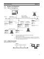
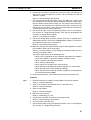
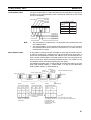
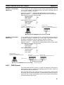
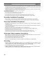
System Configuration
Device Configuration
Workstation or personal computer
CX-Programmer
Ethernet (10 Mbps)
500 m/segment max.
10Base-5 coaxial cable
(or 10Base-T twisted-pair cable)
Between nodes:
Integral multiples of 2.5 m
Terminator
Terminator
Ground
Transceiver
50 m max.
CS-series PC
Transceiver cable
CS-series
CS1W-ETN11
Ethernet Unit
(10Base-T)
100 m max.
CS-series
CS1W-ETN01
Ethernet Unit
(10Base-5)
CVM1/CV-series
PC
CJ-series
CJ1W-ETN11
Ethernet Unit
(10Base-T)
CS-series
PC
CJ-series
PC
CVM1/CV Ethernet Unit
(10Base-5)
CS-series Controller Link Unit
Controller Link network
CS-series PC
CX-Programmer
C200HX/HG/HE PC
FA computer
Note
1. Transmission distance (from Terminator to Terminator):
500 meters/segment max.
2. When segments are indirectly connected by a repeater: 2.5 km/network
3. Node interval (from transceiver to transceiver): Integral multiples of 2.5 m
4. Transceiver cable length: 50 m max.
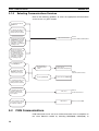
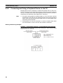
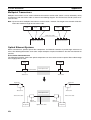
1-2-2
Node Connections
Minimal Configuration: 1 Segment
10Base-5
Node
10Base-T
Node
Node
Node
Node
1 segment
Hub
3
Section 1-3
Devices Required in a Network
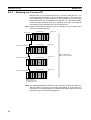
Configuration With
Segment Extension
Use repeaters to extend the distance between nodes or to increase the number of connected nodes.
10Base-5
Node
1-3
Repeater
Node
Node
Node
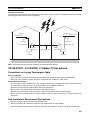
Devices Required in a Network
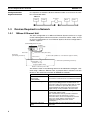
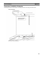
1-3-1
10Base-5 Ethernet Unit
The basic configuration of a 10Base-5 Ethernet System consists of a single
coaxial cable together with the transceivers, transceiver cables, nodes, and so
on, that are connected to it. In an Ethernet System, this basic configuration is
called a “segment.”
CS1W-ETN01 Ethernet Unit
24-VDC
power supply
50 m max.
Terminator
(terminating resistance)
Transceiver cable (AUI cable)
Transceivers
Coaxial cable (10Base-5, outer diameter approx. 10 mm)
2.5 m min.
(multiple of 2.5 m)
Terminator (terminating resistance)
Segment (500 m max.)
Number of branch points: 100
The devices shown in the following table must be obtained to configure a network using a 10Base-5 Ethernet Unit, so prepare them in advance. Use only
devices in the network that conform to IEEE802.3 standards.
Network device
The 10Base-5 Ethernet Unit is a Communications Unit
that connects a CS-series PC to an Ethernet network.
24-VDC power supply
This is a external 24-VDC power supply for the
purpose of providing power to the transceivers via
transceiver cable. Use a power supply with an output
current of at least 0.3 A per node. The power is
converted within the Unit to the transceiver power
supply voltage, and is provided to the transceiver.
The transceiver is a device for interfacing between the
coaxial cable and the nodes.
Note: The Ethernet Unit can provide a maximum
current of 0.4 A to the transceiver, so use a
transceiver with a current consumption of not more
than 0.4 A. Check with the manufacturer for
information regarding transceiver current
consumption.
Transceiver
Transceiver cable (AUI
cable)
4
Contents
CS-series 10Base-5
Ethernet Unit
(CS1W-ETN01)
This is the cable for connecting between transceivers
and nodes.
Section 1-3
Devices Required in a Network
Note
Network device
Coaxial cable
Contents
The coaxial cable comprises the main line of the
Ethernet System.
Terminator for coaxial cable
(terminating resistance)
The Terminators connect to both ends of the coaxial
cable.
1. It is also possible to use 10Base-T twisted-pair cable by connecting the
Ethernet Unit to a 10Base-T conversion adapter.
2. A 24-VDC power supply is required even if a 10Base-T conversion adapter
is used.
10Base-T conversion adapter
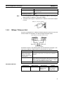
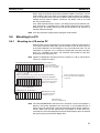
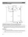
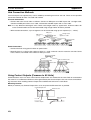
1-3-2
10Base-T Ethernet Unit
The basic configuration of a 10Base-T Ethernet System consists of one hub
to which nodes are attached in star form through twisted-pair cable.
CS1W-ETN11/CJ1W-ETN11 Ethernet Units
Twisted-pair cables
100 m max.
100 m max.
Hub
The devices shown in the following table must be obtained to configure a network using a 10Base-T Ethernet Unit, so prepare them in advance.
Network device
Contents
CS-series 10Base-T
Ethernet Unit (CS1WETN11) or CJ-series
10Base-T Ethernet Unit
(CJ1W-ETN11)
Twisted-pair cable
Hub
The 10Base-T Ethernet Units are Communications Units
that connect a CS-series or CJ-series PCs to Ethernet
networks.
A twisted-pair cable that connects the 10Base-T Ethernet
Unit to the hub. The twisted-pair cable must have an RJ45
Modular Connector attached to each end. Use a category
3, 4, or 5 UTP (unshielded twisted-pair) cable.
A relay devices that connect multiple nodes in as star LAN.
Recommended Hub
Manufacturer
Allied Telesis
Model number
MR820TLX
Specifications
9-port hub with
10Base-5 backbone port
Inquires
Allied Telesis
(0120) 86-0442
(in Japan only)
5
Section 1-4
Related Programming Devices
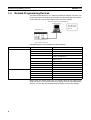
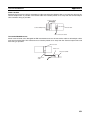
1-4
Related Programming Devices
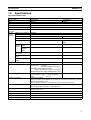
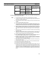
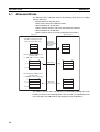
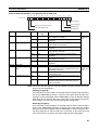
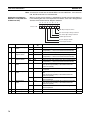
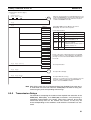
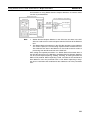
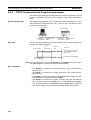
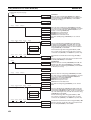
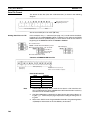
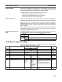
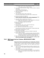
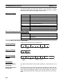
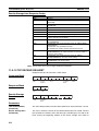
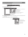
The Ethernet Unit functions as a node on the Ethernet network. The basic settings for operation are made in the CPU Bus Unit System Setup in the CS/CJseries CPU Unit. Use the CX-Programmer to make the settings.
Personal computer running Windows
CX-Programmer
CPU Bus Unit
System Setup
Screen
Ethernet Unit
CS/CJ-series CPU Unit
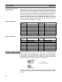
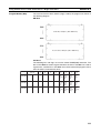
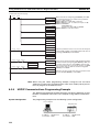
The following items are included in the System Setup.
Screen
Setup Screen
Item
All 1 (4.3BSD specifications)
Automatic generation
FINS UDP port number
Local IP address (CJ Series only)
FTP login name
9600
0.0.0.0 (Set the IP address in the allocated
words in the DM Area.)
0.0.0.0 (Uses value corresponding to IP
address class.)
CONFIDENTIAL
FTP password
IP address table
Not set.
Not set.
IP router table
Mail settings
Not set.
None set.
User-created mail data address
Local node address
Not set.
Not set.
Destination address
SMTP server address
Not set.
0.0.0.0 (Not set.)
Subnetwork mask
Mail Setup Screen
Default
Broadcast setting
Address conversion method
When using the default values that are already stored in the CS/CJ-series
CPU Unit, there is no need to make any settings with the CX-Programmer.
Refer to 4-2 CPU Bus Unit System Setup for details on the above settings.
6
Section 1-5
Specifications
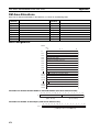
1-5
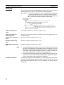
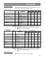
Specifications
CS-series Ethernet Units
Item
Specifications
Model number
CS1W-ETN01
CS1W-ETN11
Type
Applicable PCs
10Base-5
CS-series PCs
10Base-T
Unit classification
Mounting location
CS-series CPU Bus Unit
CPU Rack or Expansion Rack
Number of Units that can be
mounted
4 max. (including Expansion Racks)
Transfer
specifications
Media access method
Modulation
CSMA/CD
Baseband
Transmission paths
Baud rate
Bus
10 Mbps
Star
Transmission media
Coaxial cable
Unshielded twisted-pair (UTP)
cable
TransSegment
mission length
distance Distance
between
nodes
500 m max.
100 m max.
2,500 m max.
---
Number of connectable nodes
100/segment max.
---
Multiples of 2.5 m
---
50 m max.
---
400 mA max. at 5 VDC
400 mA max. at 5 VDC
External power supply
Capacity:
Inrush current:
---
Power supply to transceiver
Capacity:
0.4 A at 12 V
--Voltage fluctuation range: 13.05 to 14.48 VDC
Ripple:
2% p-p
Conforms to JIS 0040.
10 to 57 Hz, 0.075-mm amplitude, 57 to 150 Hz, acceleration: 9.8 m/s2 in X, Y, and Z
directions for 80 minutes each
(Time coefficient; 8 minutes × coefficient factor 10 = total time 80 minutes)
Distance between
nodes
Transceiver cable
length
Current consumption (Unit)
Vibration resistance
Shock resistance
0.3 A min. at 24 VDC (per node)
2.5 A max.
(24-VDC startup time of 5 ms)
Permissible voltage fluctuation range:
20.4 to 26.4 VDC (24 VDC –15% to +10%)
Recommended power supply: OMRON S82J-series
Humidity
Conforms to JIS 0041.
147 m/s2 three times each in X, Y, and Z directions
Operating: 0 to 55°C
Storage: –20 to 75°C
10% to 90% (with no condensation)
Atmosphere
Weight
Must be free from corrosive gas.
300 g max.
Dimensions
35 x 130 x 101 mm (W x H x D)
Ambient temperature
7
Section 1-5
Specifications
CJ-series Ethernet Units
Item
Specifications
Model number
CJ1W-ETN11
Type
Applicable PCs
10Base-T
CJ-series PCs
Unit classification
Mounting location
CJ-series CPU Bus Unit
CPU Rack or Expansion Rack
Number of Units that can be mounted
Transfer Media access method
specifiModulation
cations
Transmission paths
4 max. (including Expansion Racks)
CSMA/CD
Baud rate
Transmission media
Transmission
Segment
distance
length
Current consumption (Unit)
Vibration resistance
Baseband
Star
10 Mbps
Unshielded twisted-pair (UTP) cable
100 m max.
380 mA max. at 5 VDC
Humidity
Conforms to JIS 0040.
10 to 57 Hz, 0.075-mm amplitude, 57 to 150 Hz, acceleration: 9.8 m/s2 in X, Y,
and Z directions for 80 minutes each
(Time coefficient; 8 minutes × coefficient factor 10 = total time 80 minutes)
Conforms to JIS 0041.
147 m/s2 three times each in X, Y, and Z directions
Operating: 0 to 55°C
Storage: –20 to 75°C
10% to 90% (with no condensation)
Atmosphere
Weight
Must be free from corrosive gas.
100 g max.
Dimensions
31 x 90 x 65 mm (W x H x D)
Shock resistance
Ambient temperature
8
Section 1-5
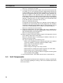
Specifications
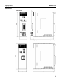
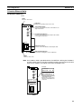
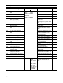
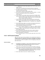
Dimensions
6.6
130
CS1W-ETN01
35
15
101
(16.5 including cover)
(Unit: mm)
130
CS1W-ETN11
35
101
(Unit: mm)
9
Section 1-6
Software Configuration
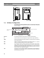
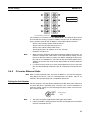
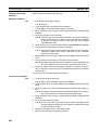
CJ1W-ETN11
65
2.7
31
ETN11
RUN ERC SD
RD
ERH TCP FTP
EF012
6789
345
ABCD
EF012
6789
345
TS
UNIT
No.
NODE
No.
x161
ABCD
EF012
6789
345
ABCD
90
x160
2.7
ETHERNET
1-6
(Unit: mm)
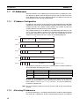
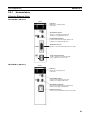
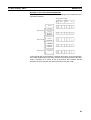
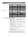
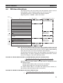
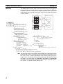
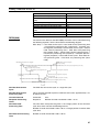
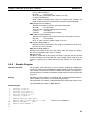
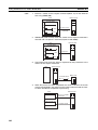
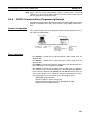
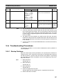
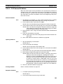
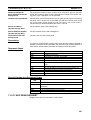
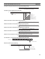
Software Configuration
The software supported by the Ethernet Unit runs in the layers shown in the
following diagram. The components that form the various layers are defined
below the diagram.
Memory Card/
EM File Memory
CS/CJ-series PC's CPU
FINS Communication
Service
Socket
Socket
Services Services
Mail
transmissions
SMTP
FINS
UDP
IP
FTP server
TCP
ICMP
CS/CJ-series PC's CPU Unit
FTP
Ethernet Unit
ARP
Ethernet (V2.0)
Ethernet
The Version-2.0 Ethernet frame format is used for communications.
IP
Internet Protocol: Transfers datagrams to target nodes using IP addresses.
ICMP
Internet Control Message Protocol: Supports IP communications by signalling
errors in data transfers.
ARP
Address Resolution Protocol: Determines the Ethernet address (i.e., physical
address) by broadcasting based on the target IP address.
UDP
User Datagram Protocol: Performs datagram communications. Data resends,
priority control, flow control, and other measures to ensure communications
reliability are not performed for UDP communications, i.e., there is no way of
guaranteeing normal communications without programming special measures
to do so into the user’s application program.
TCP
Transmission Control Protocol: Performs communications after establishing a
connection (i.e., a virtual circuit) with the target node to provide a highly reliable communications method.
10
Section 1-6
Software Configuration
FINS
Factory Interface Network Service: A protocol that sends messages between
PCs on any of various OMRON FA networks. The user must provide measures such as retry processing to ensure that transmitted messages arrive at
the destination node.
SMTP
Simple Mail Transfer Protocol: A communications protocol for sending e-mail
by TCP/IP.
FTP
File Transfer Protocol: Transfers data files.
11
Section 1-7
IP Addresses
1-7
IP Addresses
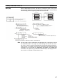
Ethernet networks use IP addresses for communications. IP addresses (Internet addresses) identify both the Ethernet network and the node (host computer, Ethernet Unit, etc.) on the Ethernet network. IP addresses must be set
and controlled so that they are not duplicated.
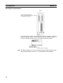
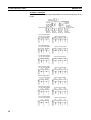
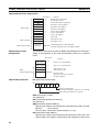
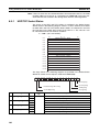
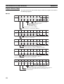
1-7-1
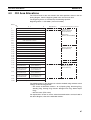
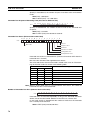
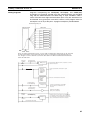
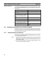
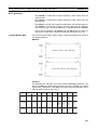
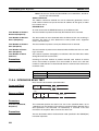
IP Address Configuration
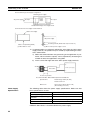
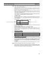
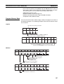
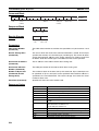
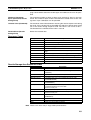
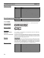
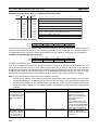
IP addresses are made up of 32 bits of binary data divided into four 8-bit fields
called octets. These four octets provide the network number (net ID) and host
number (host ID). The network number identifies the network and the host
number identifies the node (or host) on the network.
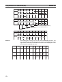
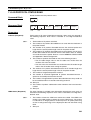
The network numbers in an IP addresses are divided into three classes, A, B,
and C, so that the address system can be selected according to the scale of
the network. (Classes D and E are not used.) The configuration of the IP
address for each of these classes is shown in the following diagram.
23
Bit 31
Class A
0
00
Network number (7 bits)
Host number (24 bits)
Bit 31
Class B
1
15
0
Network number (14 bits)
Host number (16 bits)
Bit 31
Class C
1
00
7
1
0
Network number (21 bits)
00
Host number (8 bits)
Bit 31
Class D
1
00
1
1
0
Multicast address
(Cannot be used.)
Bit 31
Class E
1
00
1
1
1
Test address
(Cannot be used.)
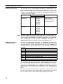
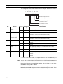
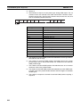
The number of networks in each class and the number of nodes possible on
the network differ according to the class.
Class
Class A
Number of networks
Small
Class B
Medium
Class C
Large
Number of hosts
24
– 2 max. (16,777,214 max.)
16
– 2 max. (65.534 max.)
2
2
8
2 – 2 max. (254 max.)
IP addresses are represented by the decimal equivalent of each of the four
octets in the 32-bit address, each separated by a period. For example, the
binary address 10000010 00111010 00010001 00100000 would be represented as 130.58.17.32.
Note The same network number must be set for every node on the same Ethernet
network.
1-7-2
Allocating IP Addresses
IP (Internet Protocol) is a standard communications protocol used throughout
the world and is designed to enable communications between any Ethernet
12
Section 1-7
IP Addresses
nodes regardless of the networks on which they exist. To achieve this, network numbers are allocated by the Network Solutions, InterNIC Registration
Services, to ensure that all Ethernet networks have unique numbers regardless of where they exist. The local system administrator is left the responsibility of allocating unique host numbers locally. You therefore should obtain a
network number from the InterNIC Registration Services to ensure uniqueness and allow for future network expansions if required.
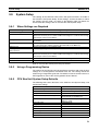
1-7-3
IP Address Settings
An IP address must be set for the Ethernet Unit before Ethernet communications can proceed. The IP address is set for each CS-series Ethernet Unit
using the rotary switch on the back of the Unit. For more details, refer to Setting the Local IP Address. The IP address for each CJ-series Ethernet Unit is
set in the DM Area words allocated to CPU Bus Units or the CPU Bus Unit
System Setup using a Programming Device. For more details, refer to 4-2
CPU Bus Unit System Setup or 4-4 DM Area Allocations.
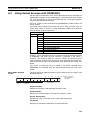
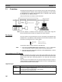
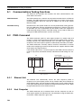
1-7-4
Subnet Masks
Operation and management of a network may become very difficult if too
many nodes are connected on a single network or if a single organization has
to manage too many network numbers. It can therefore be convenient to
divide a single network up into several subnetworks by using part of the host
number as a subnet number. Internally the network can be treated as a number of subnetworks, but from the outside it acts as a single network and uses
only a single network number.
To establish subnetworks, the host number in the IP address is divided into a
subnet number and a host number by using a setting called the subnet mask.
The subnet mask indicates which part of the host number is to be used as the
subnet number. The user must first determine the number of bits of the host
number to be used as the subnet number and then set the subnet mask
accordingly. All bits in the subnet mask that correspond to the bits in the IP
address used either as the network number or subnet number are set to “1”
and the remaining bits, which will correspond to the bits in the IP address
actually used for the host number, are set to “0”.
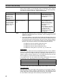
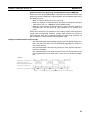
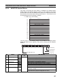
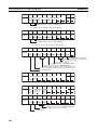
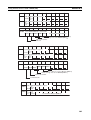
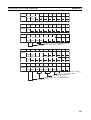
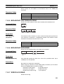
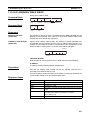
The following example shows the subnet mask for an 8-bit subnet number
used in a class-B IP address. This subnet mask is structured as follows:
This would thus be a class-B IP address masked as a class-C IP address, i.e.,
externally it would be allocated a class-B IP address but internally it can be
addressed using class-C IP addresses.
Subnet mask: 11111111 11111111 11111111 00000000 (FFFFFF00)
It is only necessary to set subnet masks if subnetworks are used. If a subnet
mask is not set by the user, a default mask will be set automatically according
to the IP address class to indicate that the entire host number will be used as
the host number, i.e., no bits will be assigned for use as the subnet number.
All nodes on the network that are going to belong to the same subnetwork
must have the same subnet mask.
In this case, the following subnet mask values will be used depending on the
IP address class.
Class
Network mask value
Class A
Class B
255.0.0.0
255.255.0.0.0
Class C
255.255.255.0.0.0
13
Section 1-8
Precautions
1-8
Precautions
Be sure to observe the following precautions when installing and using an
Ethernet Unit.
1-8-1
Installation
Observe the following precautions when installing an Ethernet System. (Refer
to Section 3 Installation and Initial Setup for details.)
1,2,3...
1. Use transceiver cable that meets IEEE802.3 standards to ensure high
noise resistance.
2. Use a transceiver with a current consumption of not more than 0.4 A per
port.
3. Always turn off the power supply to the PC before connecting or disconnecting the transceiver cable.
4. Be sure not to exceed the current capacity of the Power Supply Unit on the
Rack to which the Ethernet Unit is mounted. The current consumption of
the CS-series Ethernet Units is 400 mA maximum and the current consumption of the CJ-series Ethernet Unit is 380 mA maximum. This value
added to the current consumption of all other Units mounted to the same
Rack must not exceed the capacity of the Power Supply Unit.
5. Do not install the transceiver cables or coaxial cables of the Ethernet System near power supply lines. If installation near possible sources of noise
is unavoidable, install the cables in grounded metal ducts or take other
measure to eliminate noise interference.
1-8-2
Ethernet and IEEE802.3 Standards
The Ethernet Unit was designed based on version-2 Ethernet standards and
not on the international IEEE802.3 standards, which were developed based
on Version-2.0 Ethernet specifications. Although these two sets of standards
are similar, they are not necessarily the same. Particularly, different frame formats are used, making direct communications impossible between systems
that do not support the same standards. Standards for equipment used to
configure networks are the same, allowing IEEE802.3-standard equipment to
be used with the Ethernet Unit. Particularly the transceiver cable for the
IEEE802.3 standards provides superior noise resistance and should be used
for the Ethernet Unit.
Terminology also differs between Version-2.0 Ethernet and IEEE802.3 standards. These differences are shown in the following table. Version-2.0 Ethernet terminology is used in this manual.
14
Version-2 Ethernet
Transceiver
MAU
IEEE802.3
Transceiver cable
Ethernet address
AUI
MAC address
Ethernet
10Base-5/10Base-T
SECTION 2
Communications Functions
This section provides an overview of the communications functions that can be used with the Ethernet Unit.
2-1
Communications Functions. . . . . . . . . . . . . . . . . . . . . . . . . . . . . . . . . . . . . . .
16
2-1-1
Ethernet Unit Functions . . . . . . . . . . . . . . . . . . . . . . . . . . . . . . . . . .
17
2-1-2
Socket Ports Used By the Ethernet Unit. . . . . . . . . . . . . . . . . . . . . .
17
2-1-3
Selecting Communications Services. . . . . . . . . . . . . . . . . . . . . . . . .
18
2-2
FINS Communications . . . . . . . . . . . . . . . . . . . . . . . . . . . . . . . . . . . . . . . . . .
18
2-3
Socket Services . . . . . . . . . . . . . . . . . . . . . . . . . . . . . . . . . . . . . . . . . . . . . . . .
19
2-4
FTP Server . . . . . . . . . . . . . . . . . . . . . . . . . . . . . . . . . . . . . . . . . . . . . . . . . . .
21
2-5
Mail . . . . . . . . . . . . . . . . . . . . . . . . . . . . . . . . . . . . . . . . . . . . . . . . . . . . . . . . .
21
15
Section 2-1
Communications Functions
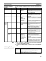
2-1
Communications Functions
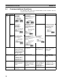
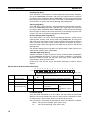
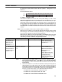
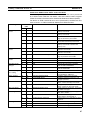
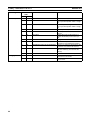
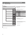
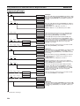
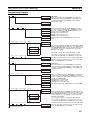
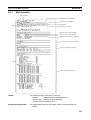
The following table shows the communications service functions that are
available with the Ethernet Unit.
Function
Client PC to PC
to
server
FINS communications
By executing
SEND(090),
RECV(098),
or CMND(490)
FINS command
Socket services
FTP server
--By executing
CMND(490) or
manipulating dedicated
control switches in
memory.
Mail
---
Any data
PC to host By executing
computer SEND(090),
RECV(098), or
CMND(490)
Host computer (with
FINS Gateway function)
FINS command
--At PC: By executing
CMND(490) or
manipulating dedicated
control switches in
memory.
E-mail can be set to be
sent when specified
bits turn ON, when
errors occur, or at
fixed intervals.
Host computer (without
FINS Gateway function)
(Passive open)
Mail server
E-mail
Any data
(Active open)
Host computer to
PC
By sending FINS
messages from the
host computer.
Host computer
(with FINS Gateway function)
FINS command
At PC: By executing
CMND(490) or
manipulating dedicated
control switches in
memory.
FTP commands
executed by
host computer
---
Host computer
File
Host computer (without FINS Gateway
function)
(Active open)
Any data
(Passive open)
Data type
FINS commands (vari- Any data (PC’s internal
ous commands for I/O I/O memory)
memory communications in the PC, changing the operating mode,
reading and writing
files, and so on)
DOS files in File Mem- User-defined mesory (Memory Card or
sages, error log inforEM File Memory)
mation, status
information
Maximum data size
PC to PC: 1,980 bytes
max.
PC to host computer:
1,980 bytes max.
Host computer to PC:
2,000 bytes max.
1,984 bytes max.
No particular limit.
User-defined messages: 1,024 bytes
max.
Features
Enables control of PC
and host computer that
support FINS commands.
Communications by
standard TCP/IP and
UDP/IP via Ethernet.
No need to set FINS
addresses.
Ethernet Unit status is
obtained by e-mail.
Notification of errors is
received by e-mail.
Reference
Section 5 FINS Communications
Section 6 Socket Services
Files are read by
means of simple commands and applications from host
computers with FTP
client functions.
Section 7 FTP Server
16
Section 8 Mail
Section 2-1
Communications Functions
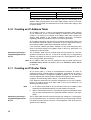
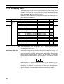
2-1-1
Ethernet Unit Functions
Function
Contents
FINS communications
• A SEND(090), RECV(098), or CMND(490) instruction from the PC’s ladder program is used to send a FINS command to a remote node, and a
response is received.
• A FINS command is received from a remote node. If the command is
addressed to the local Unit, it is processed internally. If it is addressed to
another Unit, a request is made to the CPU Unit and the result is sent
back to the remote node as a response.
• Following the FINS header information, the Ethernet Unit serves as a
gateway for FINS commands and responses between other Communications Units mounted to the same PC.
Socket services
The Ethernet Unit supports up to 16 ports (8 TCP ports and 8 UDP ports)
for socket interface with respect to the ladder program. When this function
is used, communications can be carried out by either TCP or UDP with various devices on the Ethernet network.
This function can be used by either manipulating dedicated control
switches in memory or by executing CMND(490).
1) Manipulating dedicated control switches in memory:
Socket services can be used by first setting the required parameters in
the Socket Service Parameter Area allocated in the DM Area (refer
to4-4 DM Area Allocations) and then turning ON dedicated control
switches in memory.
There is no need to monitor the completion timing for instructions or
socket services, so the work hours involved in developing ladder programs can be reduced.
Only eight socket ports (UDP and TCP combined) can be used with
this method. For any ports that exceed that number, use the
CMND(490) instruction.
2) Using CMND(490)
Socket services can be used by utilizing the CMND(490) instruction to
execute FINS commands. Up to 16 socket ports can be used with
CMND(490).
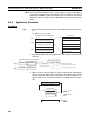
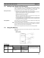
FTP server
The FTP server function allows data files to be transferred between a client
workstation or personal computer and the PC’s file system (Memory Card
or EM Area).
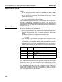
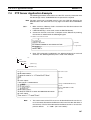
The types of data listed below can be sent as e-mail when a dedicated control switch in memory is turned ON, when an error occurs, or when a preset
time interval elapses. Any of the following types of data can be specified for
transmission with any of these timing methods. (Refer to Section 8 Mail.)
• User-created data (Data at PC: ASCII, 1,024 bytes max.)
• Error log information (64 records)
• Status information
A mail server must be provided separately in order to use the mail function.
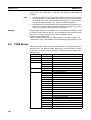
Mail
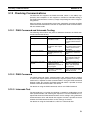
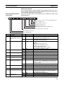
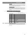
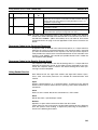
2-1-2
UDP
TCP
Socket Ports Used By the Ethernet Unit
Port number
9600
20
21
Application
Used for FINS. (Can be changed by CPU Bus Unit System Setup.)
Used for FTP server function (for data transfer).
Used for FTP server function (for connection).
17
Section 2-2
FINS Communications
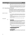
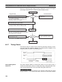
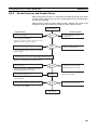
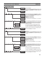
2-1-3
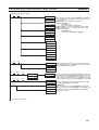
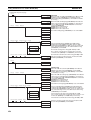
Selecting Communications Services
Refer to the following guidelines to select the appropriate communications
service to use in a given situation.
To communicate with an
OMRON PC.
To communicate with a host
computer (with the FINS
gateway function enabled).
FINS Communications
To perform operations with
an OMRON PC other than
sending or receiving data
(for example, reading or
writing files or changing the
operating mode).
Refer to
Section 5 FINS Communications.
To perform operations
with a host computer (with
the FINS gateway function enabled) other than
sending or receiving data
(for example, reading or
writing files or changing
the operating mode).
To communicate with a
non-OMRON PC.
By manipulating a
dedicated control
switch.
Socket services
(control switch manipulation)
To communicate with an
OMRON PC within the
socket services system.
Refer to
Section 6 Socket Services.
By using CMND(490).
Socket services (CMND(490))
To communicate with a host
computer (with the FINS
gateway function disabled).
To designate from the host
computer a file transfer
between the PC and the
host computer.
FTP server
To send e-mail from the PC
to the mail server by any of
the required conditions.
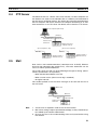
2-2
Mail Service
Refer to
Section 7 FTP Server.
Refer to Section 8 Mail.
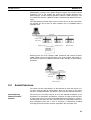
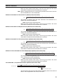
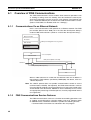
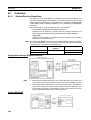
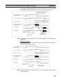
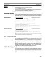
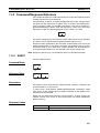
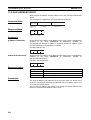
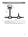
FINS Communications
FINS commands can be sent to or received from other PCs or computers on
the same Ethernet network by executing SEND(090), RECV(098), or
18
Section 2-3
Socket Services
CMND(490) instructions in the ladder-diagram program. This enables control
operations such as the reading and writing of I/O memory between PCs,
mode changes, and file memory operations. (When a FINS message is sent
on an Ethernet network, a UDP/IP header is automatically added to the message.)
The FINS gateway function allows access not only to PCs on the same Ethernet network, but also to PCs on other networks such as SYSMAC LINK or
Controller Link.
Ethernet
CS/CJ-series
CPU Unit
Ethernet Unit
Ethernet Unit
Ethernet Unit
User program
SEND(090,
RECV(098), or
CMND(490)
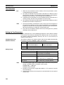
Executing from the host computer FINS commands with UDP/IP headers
added enables various control operations such as the reading and writing of
I/O memory of PCs on the Ethernet network, mode changes, and file memory
operations.
Ethernet
CS/CJ-series
CPU Unit
Ethernet Unit
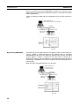
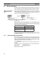
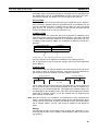
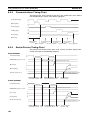
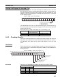
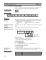
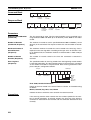
2-3
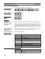
Socket Services
The socket services allow devices on the Ethernet to send and receive various data using the UDP or TCP protocol. There are two ways to use socket
services, as explained below. (For details, refer to Section 6 Socket Services.)
By Manipulating
Dedicated Control
Switches
The first way to use socket services is to set the required parameters in the
parameter area allocated in the DM Area, and then to request particular UDP
or TCP socket services by turning ON dedicated control switches in memory.
The Ethernet Unit turns OFF the same bit when the requested process has
been completed. Data that is sent or received is automatically handled
according to the I/O memory locations specified in the parameter area.
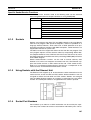
19
Section 2-3
Socket Services
There is no need to execute the CMND(490) instruction or to monitor the completion timing and actual processing of the instruction, so this helps to simplify
ladder programming.
A total of eight ports (UDP and TCP combined) can be used for socket services.
UNIX computer, etc.
(node with socket services interface)
Ethernet
Ethernet Unit
TCP/UDP protocol
Socket
CS/CJ-series
CPU Unit
Socket Service Request Switches
Parameters
TCP/UDP
protocol
Ethernet Unit
By Executing CMND(490)
CS/CJ-series
CPU Unit
The other way to use socket services is to request a UDP or TCP socket service by sending a FINS command to the Ethernet Unit by executing
CMND(490) from the CPU Unit. When the Ethernet Unit receives the socket
service request, it returns a response to the CPU Unit to confirm that it
received the request and then begins the requested processing. When the
processing is completed, the results are stored in the Results Storage Area in
the CPU Unit.
Eight TCP ports and eight UDP ports can be used.
UNIX computer, etc.
(node with socket
services interface)
Ethernet
TCP/UDP protocol
Ethernet Unit
CS/CJ-series
CPU Unit
TCP protocol
Socket
FINS command
FINS response
Results Storage Area
Processing results
UDP protocol
Socket interface
Ethernet Unit CS/CJ-series
CPU Unit
20
Section 2-4
FTP Server
2-4
FTP Server
The Ethernet Unit has a built-in FTP server function, so other computers on
the Ethernet can read or write individual files in a Memory Card mounted to
the CPU Unit or in EM file memory. This allows files to be exchanged between
the host computer and the PC, with the host computer functioning as an FTP
client and the PC as an FTP server. For details, refer to Section 7 FTP Server.
Host computer (FTP client)
Ethernet
FTP command
Ethernet Unit
CS/CJ-series
CPU Unit
Memory Card or
EM file memory
(Host computer to PC)
File data
(PC to host computer)
File data
Memory Card or
EM file memory
Memory Card or
EM file memory
2-5
Mail
Data such as user-created information (1,024 bytes max. in ASCII), Ethernet
Unit error log information (64 records max.), and status information can be
sent as e-mail to specified addresses.
The e-mail can be sent with any of the following three types of timing. (Simultaneous specification is also possible.)
• When the Mail Send Switch turns ON.
• When an error occurs (when an error log is recorded.)
• At regular intervals.
This enables periodic e-mail and error messages to be sent from the PC to
the mail server.
Mail server
Ethernet
Mail
Ethernet Unit
CS/CJ-series
CPU Unit
Note
1. A mail server is required in order to use the mail function.
2. Mail server settings require specialized knowledge, so they should always
be handled by the network administrator.
3. Be sure you have a clear understanding of the mail system before using
this function.
21
Mail
Section 2-5
4. Mail delivery is not guaranteed. Depending on factors such as the condition of the network, mail that has been sent may not arrive at its destination.
22
SECTION 3
Installation and Initial Setup
This section explains how to install the Ethernet Unit and make the initial settings required for operation.
3-1
Before Operation. . . . . . . . . . . . . . . . . . . . . . . . . . . . . . . . . . . . . . . . . . . . . . .
24
3-1-1
Automatic Address Generation. . . . . . . . . . . . . . . . . . . . . . . . . . . . .
24
3-1-2
IP Address Table. . . . . . . . . . . . . . . . . . . . . . . . . . . . . . . . . . . . . . . .
25
3-2
Overview of Startup Procedure . . . . . . . . . . . . . . . . . . . . . . . . . . . . . . . . . . . .
26
3-3
Unit Components . . . . . . . . . . . . . . . . . . . . . . . . . . . . . . . . . . . . . . . . . . . . . .
28
3-4
3-5
3-6
3-7
3-8
3-9
3-3-1
Nomenclature . . . . . . . . . . . . . . . . . . . . . . . . . . . . . . . . . . . . . . . . . .
29
3-3-2
Indicators . . . . . . . . . . . . . . . . . . . . . . . . . . . . . . . . . . . . . . . . . . . . .
32
Switch Settings . . . . . . . . . . . . . . . . . . . . . . . . . . . . . . . . . . . . . . . . . . . . . . . .
33
3-4-1
CS-series Ethernet Units. . . . . . . . . . . . . . . . . . . . . . . . . . . . . . . . . .
33
3-4-2
CJ-series Ethernet Units . . . . . . . . . . . . . . . . . . . . . . . . . . . . . . . . . .
35
Mounting to a PC . . . . . . . . . . . . . . . . . . . . . . . . . . . . . . . . . . . . . . . . . . . . . .
37
3-5-1
Mounting to a CS-series PC . . . . . . . . . . . . . . . . . . . . . . . . . . . . . . .
37
3-5-2
Mounting to a CJ-series PC . . . . . . . . . . . . . . . . . . . . . . . . . . . . . . .
38
Connecting to the Network . . . . . . . . . . . . . . . . . . . . . . . . . . . . . . . . . . . . . . .
39
3-6-1
Ethernet Network Installation. . . . . . . . . . . . . . . . . . . . . . . . . . . . . .
39
3-6-2
Ethernet Connectors . . . . . . . . . . . . . . . . . . . . . . . . . . . . . . . . . . . . .
39
3-6-3
Connecting the Cable . . . . . . . . . . . . . . . . . . . . . . . . . . . . . . . . . . . .
40
3-6-4
Connecting the Power Supply (CS1W-ETN01 Only) . . . . . . . . . . .
42
Creating an I/O Table . . . . . . . . . . . . . . . . . . . . . . . . . . . . . . . . . . . . . . . . . . .
45
3-7-1
I/O Table Overview. . . . . . . . . . . . . . . . . . . . . . . . . . . . . . . . . . . . . .
45
3-7-2
Connecting Programming Devices to the PC . . . . . . . . . . . . . . . . . .
45
3-7-3
Procedure for Creating an I/O Table. . . . . . . . . . . . . . . . . . . . . . . . .
45
Creating Routing Tables . . . . . . . . . . . . . . . . . . . . . . . . . . . . . . . . . . . . . . . . .
46
3-8-1
Routing Table Overview . . . . . . . . . . . . . . . . . . . . . . . . . . . . . . . . . .
46
3-8-2
Connecting and Using a Peripheral Device for the PC. . . . . . . . . . .
48
System Setup. . . . . . . . . . . . . . . . . . . . . . . . . . . . . . . . . . . . . . . . . . . . . . . . . .
51
3-9-1
When Settings are Required . . . . . . . . . . . . . . . . . . . . . . . . . . . . . . .
51
3-9-2
Using a Programming Device. . . . . . . . . . . . . . . . . . . . . . . . . . . . . .
51
3-9-3
CPU Bus Unit System Setup Defaults . . . . . . . . . . . . . . . . . . . . . . .
51
3-10 Creating an IP Address Table . . . . . . . . . . . . . . . . . . . . . . . . . . . . . . . . . . . . .
52
3-11 Creating an IP Router Table . . . . . . . . . . . . . . . . . . . . . . . . . . . . . . . . . . . . . .
52
3-12 Checking Communications . . . . . . . . . . . . . . . . . . . . . . . . . . . . . . . . . . . . . . .
53
3-12-1 PING Command and Internode Testing . . . . . . . . . . . . . . . . . . . . . .
53
3-12-2 PING Command . . . . . . . . . . . . . . . . . . . . . . . . . . . . . . . . . . . . . . . .
53
3-12-3 Internode Test . . . . . . . . . . . . . . . . . . . . . . . . . . . . . . . . . . . . . . . . . .
53
3-12-4 Simple Startup Test Example . . . . . . . . . . . . . . . . . . . . . . . . . . . . . .
54
23
Section 3-1
Before Operation
3-1
Before Operation
In order to connect the Ethernet Unit to an Ethernet network, it is necessary to
set the IP address. This section explains the process of address conversion,
which is required information for determining the Ethernet Unit’s IP address.
Address Conversion (for
FINS Communications
Only)
When using the FINS communication service, it is necessary to specify the
nodes according to the FINS address system. Even in this case, data must be
sent and received on the Ethernet network using IP addresses. Therefore, IP
addresses are converted from FINS addresses.
Ethernet Unit
Ethernet Unit
User program
CS/CJ-series
CPU Unit
Data
IP address: 153.211.32.114
Node number: 23
Network address: 5 To
Node number: 23
Address conversion
To 153.211.32.114
Data
To 153.211.32.114
There are three ways to convert addresses. For each method, there are
restrictions on the maximum number nodes at the same network level for
which communications is possible. The methods and the maximum number of
nodes are shown in the following table.
Address conversion method
Maximum number of nodes
(including local node)
Automatic generation (the default) 126
IP address table
32
Combined method
(using both automatic generation
and IP address table)
126
Use the CX-Programmer to select the address conversion method in the System Setup. For an explanation of how to make the setting, refer to 4-2 CPU
Bus Unit System Setup.
3-1-1
Automatic Address Generation
Automatic address generation converts addresses using the FINS node number as the host number of the IP address. The network ID of the local IP
address is used for the network ID. The IP address of a remote node is calculated from the local Ethernet Unit’s IP address, the subnet mask, and the
remote node number (Fins node number), as follows:
Remote IP address =
(local IP address AND subnet mask) OR remote FINS node number
Example
The remote IP address is calculated for the node using the following settings:
Local IP address:
130.25.36.8 (decimal)
Subnet mask:
255.255.255.0 (decimal)
Remote FINS node number:
5
24
Section 3-1
Before Operation
130.25.36. 8
AND 255.255.255.0
OR
Local IP address
Subnet mask
130.25.36.0
5
130.25.36.5
Remote FINS node number
Remote IP address
Note The rightmost byte of the host number becomes the FINS node number, and
set the rest of the host number to all zeroes.
Example 1: Class B
Local IP address:
Subnet mask:
Remote FINS node number:
130.25.0.8
255.255.0.0
5
Host number
Remote IP address
130.25.0.5
Becomes 0.
Example 2: Class A
Local IP address:
Subnet mask:
Remote FINS node number:
130.0.0.8
255.0.0.0
5
Host number
Remote IP address
130.0.0.5
Becomes 0.
Note With CS-series Ethernet Units, when using either the address conversion
method (the default) or the combined method, set the local IP address
switches 7 and 8 on the back of the Ethernet Unit and the node number to the
same values, and set the other host settings to 0. If the values are wrong, the
ERC indicator will flash.
With CJ-series Units, when using either the address conversion method (the
default) or the combined method, set the rightmost byte of the local IP
address and the node number to the same values, and set the other host settings to 0. If the values are wrong, the ERH indicator will flash.
Characteristics of Automatic Generation Method
The automatic address generation method has the advantage of clarifying the
correspondence between the FINS address and the IP address, but it also
has the following restrictions.
1,2,3...
1. It cannot be applied outside of the range with the same network ID.
2. The remote host number must be within the range of FINS node numbers
(1 to 126).
3. The Ethernet Unit’s host number and the node number must be set to the
same value.
The automatic address generation method is the default setting, so there is no
need to set it with the CX-Programmer if the setting has not been changed.
3-1-2
IP Address Table
The IP address table method converts the FINS node number to an IP
address based on a preset correspondence table called an IP address table.
The IP address table is prepared in the System Setup, using the CX-Programmer. For details on the System Setup, refer to 4-2 CPU Bus Unit System
25
Section 3-2
Overview of Startup Procedure
Setup. With different segments, nodes with different network IDs can also be
registered.
IP address
FINS node
address
18
20
23
FINS node number
IP address table
153.214.0.62
153.214.0.129
153.218.51.8
IP address
Characteristics of IP Address Table Method
The IP address table method provides a simple correspondence table, so it
has the advantage of allowing FINS node numbers and IP address to be
freely allocated. It does, however, have the following restrictions.
1,2,3...
1. Not more than 32 pairs of node number and IP addresses can be registered in the IP address table, so that limits the number of nodes, including
the local node, to 32.
2. The correspondences must be preset, or the remote FINS node numbers
will not be recognized.
Combined Method
The combined method incorporates both the automatic generation method
and the IP address table method. It first refers to the IP address table, and if
there is an applicable FINS address, it reads the corresponding IP address. If
there is no applicable FINS address, it uses the automatic generation method
to calculate an IP address.
FINS node number
IP address table
FINS node
number
If found in
IP address table
If not found in
IP address table
3-2
18
20
23
IP address table
153.214.0.62
153.214.0.129
153.218.51.8
Host number: XX.XX.00.00
+
FINS node number: XX
IP address
IP address
Overview of Startup Procedure
CS Series
1,2,3...
1. Determine the local IP address and the address conversion method.
Refer to 3-1 Before Operation.
2. Set the unit number of the Ethernet Unit as a CPU Bus Unit.
Refer to 3-4 Switch Settings.
3. Set the node address.
Refer to 3-4 Switch Settings.
4. Set the local IP address.
Refer to 3-4 Switch Settings.
5. Mount the Unit to the Backplane.
Refer to 3-5 Mounting to a PC.
26
Section 3-2
Overview of Startup Procedure
6. Connect to the network. Connect the transceiver cable and external 24VDC power supply for 10Base-5 systems and the twisted-pair cable for
10Base-T systems.
Refer to 3-6 Connecting to the Network.
7. Turn ON the external 24-VDC power supply (for 10Base-5 systems) and
turn ON power to the CPU Unit. When turning ON the power supply, either
first turn ON the external power supply (i.e., the power to the transceiver),
and then turn ON the power to the CPU Unit afterwards, or else turn them
both ON at the same time. If the power is turned ON first to the CPU Unit,
a communications error will be generated.
8. Create the I/O tables using a Programming Device, such as CX-Programmer, CX-Net, or a Programming Console. (This step can be omitted if the
I/O table has already been created.)
Refer to 3-7 Creating an I/O Table.
9. Create the routing tables using the CX-Net. (This step is required only if
FINS communications are used, or if CMND(490) is used by a PC with multiple Communications Units mounted to it.)
Refer to 3-8 Creating Routing Tables.
10. Make the settings in the System Setup using the CX-Programmer. (Create
the IP address table and IP router table.)
Refer to 3-9 System Setup, 3-10 Creating an IP Address Table, and 3-11
Creating an IP Router Table.
This step is required only in the following cases:
• When using a method other than automatic generation for IP address
conversion. (Address conversion method, IP address table.)
• When using the mail notification function.
• When setting a subnet mask.
• When setting an FTP login name and password.
• When Ethernet is configured in multiple segments. (IP router table)
• When Ethernet 4.28 is used (broadcast settings)
• When the UDP port number for FINS is changed to something other
than the default setting (9600).
11. Check communications. (Use PING command and an internode test.)
CJ Series
1,2,3...
1. Determine the local IP address and the address conversion method.
Refer to 3-1 Before Operation.
2. Set the unit number of the Ethernet Unit as a CPU Bus Unit.
Refer to 3-4 Switch Settings.
3. Set the node address.
Refer to 3-4 Switch Settings.
4. Mount the Unit to the PC.
Refer to 3-5 Mounting to a PC.
5. Connect to the network. Connect the twisted-pair cable.
Refer to 3-6 Connecting to the Network.
6. Turn ON power to the CPU Unit.
7. Create the I/O tables using a Programming Device, such as CX-Programmer, CX-Net, or a Programming Console.
27
Section 3-3
Unit Components
Refer to 3-7 Creating an I/O Table.
8. For simple operation where the IP address only (and no other System Setup settings) is set, or for operation using the Programming Console only,
set the IP address in the allocated words in the DM Area using the CX-Programmer or Programming Console. (This method is mainly used when setting the IP address in the allocated words in the DM Area using the
Programming Console only. When using this method, be sure to set the local IP address value in the CPU Bus Unit System Setup to 00.00.00.00
(default). If a different value is set, the IP address set in the allocated words
in the DM Area will be overwritten with this value.)
Refer to 4-4 DM Area Allocations.
For operation with the System Setup set as desired, set the IP address in
the CPU Bus Unit System Setup with the CX-Programmer. This method is
used when setting the local IP address with the CX-Programmer. Any set
value other than 00.00.00.00 will be enabled as the local IP address.)
Refer to 4-2 CPU Bus Unit System Setup.
9. Create the routing tables using the CX-Net. (This step is required only if
FINS communications are used, or if CMND(490) is used by a PC with multiple Communications Units mounted to it.)
Refer to 3-8 Creating Routing Tables.
10. Make the settings in the System Setup using the CX-Programmer. (Create
the IP address table and IP router table.)
Refer to 3-9 System Setup, 3-10 Creating an IP Address Table, and 3-11
Creating an IP Router Table.
This step is required only in the following cases:
• When using a method other than automatic generation for IP address
conversion. (Address conversion method, IP address table.)
• When using the mail notification function.
• When setting a subnet mask.
• When setting an FTP login name and password.
• When Ethernet is configured in multiple segments. (IP router table)
• When Ethernet 4.28 is used (broadcast settings)
• When the UDP port number for FINS is changed to something other
than the default setting (9600).
11. Check communications. (Use PING command and an internode test.)
3-3
Unit Components
This section explains the Ethernet Unit’s components, settings, and LED indicators. For details regarding the settings, refer to the individual explanations
later in this section.
28
Section 3-3
Unit Components
3-3-1
Nomenclature
CS-series Ethernet Units
CS1W-ETN01 (10Base-5)
Front
Indicators
Display the operating status
of the Unit.
Unit Number Switch
Used to set the Ethernet Unit's unit
number in one digit hexadecimal.
Node Number Switches
Used to set the Ethernet Unit's FINS node
number in two digits hexadecimal.
Ethernet Connector
Used to connect the Ethernet transceiver cable.
Power Supply Terminals
Used to connect an external 24-VDC
power supply for the transceiver.
CS1W-ETN11 (10Base-T)
Front
Indicators
Display the operating status
of the Unit.
Unit Number Switch
Used to set the Ethernet Unit's unit
number in one digit hexadecimal.
Node Number Switches
Used to set the Ethernet Unit's FINS node
number in two digits hexadecimal.
Ethernet Connector
Used to connect the Ethernet transceiver cable.
29
Section 3-3
Unit Components
CS1W-ETN01 and CS1W-ETN11
Back
Local IP Address Switches
Used to set the Ethernet Unit's IP address
in eight digits hexadecimal.
Each communications device connected to the Ethernet network is allocated
a unique Ethernet address. For the Ethernet Unit, this Ethernet address is
shown on the right side of the Unit as a 12-digit hexadecimal number.
Ethernet address (12 digits)
Note The Ethernet address can also be checked using the FINS command, CONTROLLER DATA READ. (Refer to 11-3-2 CONTROLLER DATA READ.)
30
Section 3-3
Unit Components
CJ-series Ethernet Units
CJ1W-ETN11 (10Base-T)
Front
Slider
Mount to other Units.
Indicators
Display the operating status of the Unit.
ETN11
RUN ERC SD
RD
ERH TCP FTP
EF012
6789
345
ABCD
ABC
EF012
6789
345
TS
Unit Number Switch
Used to set the Ethernet Unit’s unit number in one
digit hexadecimal.
UNIT
No.
NODE
No.
x161
Node Number Switches
Used to set the Ethernet Unit’s FINS node number
in two digits hexadecimal.
EF012
6789
345
0
x16
ABCD
ETHERNET
Ethernet Connector
Used to connect the Ethernet twisted-pair cable.
DIN Track Mounting Pin
Used when mounting the Unit to a DIN track.
Slider
Mount to other Units.
Note An IP address label is provided with the CJ1W-ETN11. Writing the IP address
and the subnet mask on this label and then attaching it to the front of the Unit
allows the IP address and subnet mask to be confirmed easily.
ETN11
RUN ERC SD
Example
RD
ERH TCP FTP
EF012
6789
345
ABCD
EF012
6789
345
TS
UNIT
No.
NODE
No.
x161
ABCD
6789
EF012
133.113.
0. 42
SUBNET MASK
345
x160
ABCD
IP ADDRESS
133.113.
IP ADDRESS
0. 42
255.255.255.0
Attach the label to the front
of the Ethernet Unit
between the node number
switches and the Ethernet
connector.
SUBNET MASK
255.255.255.0
ETHERNET
31
Section 3-3
Unit Components
Each communications device connected to the Ethernet network is allocated
a unique Ethernet address. For the Ethernet Unit, this Ethernet address is
shown on the right side of the Unit as a 12-digit hexadecimal number.
CJ1W-ETN11
ETHERNET UNIT
Lot No.
OMRON Corporation
MADE IN JAPAN
@@@@@@@@@@@@
Ethernet Address
Ethernet address (12 digits)
Note The Ethernet address can also be checked using the FINS command, CONTROLLER DATA READ. (Refer to 11-3-2 CONTROLLER DATA READ.)
3-3-2
Indicators
The status of the indicators show the operating status of the Unit.
CS1W-ETN01 (10Base-5)
CJ1W-ETN11 (10Base-T)
CS1W-ETN11 (10Base-T)
ETN11
RUN ERC SD
RUN
ERC
SD
RD
Indicator
RUN
P/S
(Power Supply)
(CS1W-ETN01 only.)
ERC
(Ethernet Unit Error)
ERH
(PC Error)
P/S
ERH
TCP
FTP
TS
RD
ERH TCP FTP
Color
Green
Status
Meaning
Lit
• Operation stopped.
• Hardware error.
Normal operation.
Green
Not lit
Lit
Power is not being supplied to the transceiver.
Power is being supplied to the transceiver.
Red
Not lit
Lit
Unit normal.
• Node number not between 1 and 126.
• A hardware (e.g., internal memory) error has occurred.
Flashing
An illegal IP address has been set. With automatic address generation,
the rightmost two digits of the IP address do not match the node number. (Refer to Setting the Local IP Address.) This error is generated for
the CS Series only.
PC normal.
Red
Not lit
TS
Not lit
Lit
• A PC error has occurred.
• An error exists in I/O table, unit number, system data, or routing table
settings.
Flashing
SD
(Send Data)
Yellow
Not lit
An illegal IP address has been set. With automatic address generation,
the rightmost two digits of the IP address do not match the node number. (Refer to Section 4-2-1 Settings.) This error is generated for the CJ
Series only.
Not sending data. (Ready to send.)
RD
(Receive Data)
Yellow
Lit
Not lit
Sending data.
Not receiving data. (Ready to receive.)
TCP
(TCP Socket in Use)
Yellow
Lit
Not lit
Receiving data.
None of the eight TCP sockets provided for socket services is in use.
Lit
At least one of the eight TCP sockets provided for socket services is in
use.
FTP
(File Server Service)
Yellow
Not lit
Lit
FTP server on stand-by.
FTP server operating.
32
Section 3-4
Switch Settings
Indicator
TS
(Internode Testing)
3-4
Color
Yellow
Status
Not lit
Not running internode test.
Meaning
Lit
Running internode test.
Switch Settings
This section explains how to set the various switches on the Ethernet Unit.
3-4-1
CS-series Ethernet Units
Setting the Unit Number
The unit number is used to identify individual CPU Bus Units when more than
one CPU Bus Unit is mounted to the same PC. Use a small screwdriver to
make the setting, taking care not to damage the rotary switch. The unit number is factory-set to 0.
Setting range:
0 to F
Note
1. Turn OFF the power supply before setting the unit number.
2. If the unit number is being set for the first time or changed, then an I/O table
must be created for the PC.
Unit Number and CPU Bus
Unit Allocations
With CS-series PCs, words are automatically allocated in the CIO Area and
the DM Area. The Ethernet Unit uses these words for receiving control data
from the CPU Unit and for notifying the CPU Unit of Ethernet Unit and communications status. The word addresses in the allocated areas for the CPU
Bus Unit are important in creating the user program for using the Ethernet
Unit, so be careful to take them into account when setting the unit number.
The following table shows the areas allocated for the CPU Bus Unit by unit
number. This table only shows the correspondences between unit numbers
and the areas allocated for the CPU Bus Unit. For more details, refer to Section 4 System Setup and Memory Allocations.
CIO Area Allocations
Unit No.
(decimal)
Allocated words
Unit No.
(decimal)
Allocated words
0 (0)
1 (1)
CIO 1500 to CIO 1524
CIO 1525 to CIO 1549
8 (8)
9 (9)
CIO 1700 to CIO 1724
CIO 1725 to CIO 1749
2 (2)
3 (3)
CIO 1550 to CIO 1574
CIO 1575 to CIO 1599
A (10)
B (11)
CIO 1750 to CIO 1774
CIO 1775 to CIO 1799
4 (4)
5 (5)
CIO 1600 to CIO 1624
CIO 1625 to CIO 1649
C (12)
D (13)
CIO 1800 to CIO 1824
CIO 1825 to CIO 1849
6 (6)
7 (7)
CIO 1650 to CIO 1674
CIO 1675 to CIO 1699
E (14)
F (15)
CIO 1850 to CIO 1874
CIO 1875 to CIO 1899
33
Section 3-4
Switch Settings
DM Area Allocations
Unit No.
(decimal)
0 (0)
Allocated words
D30000 to D30099
Unit No.
(decimal)
8 (8)
Allocated words
D30800 to D30899
1 (1)
2 (2)
D30100 to D30199
D30200 to D30299
9 (9)
A (10)
D30900 to D30999
D31000 to D31099
3 (3)
4 (4)
D30300 to D30399
D30400 to D30499
B (11)
C (12)
D31100 to D31199
D31200 to D31299
5 (5)
6 (6)
D30500 to D30599
D30600 to D30699
D (13)
E (14)
D31300 to D31399
D31400 to D31499
7 (7)
D30700 to D30799
F (15)
D31500 to D31599
Setting the Node Number
With the FINS communications service, when there are multiple Ethernet
Units connected to the Ethernet network, the Ethernet Units are identified by
node numbers. Use the node number switches to set the node number
between 01 and 7E hexadecimal (1 to 126 decimal). Do not set a number that
has already been set for another node on the same network.
Setting range:
01 to 7E (1 to 126 decimal)
The left switch sets the sixteens digit (most significant digit) and the right
switch sets the ones digit (least significant digit). The node number is factoryset to 01.
When using the automatic generation method for address conversion, set the
node number to the same value as that of the local IP address switches. If this
is not possible, then either the IP address table method or the combined
method must be used for address conversion. For details, refer to 4-2 CPU
Bus Unit System Setup.
If the FINS communications service is not being used over the Ethernet network, then there is no problem if the node number duplicates that of another
Ethernet Unit. The node number must still be set from 01 to 7E, however, or
the ERC indicator will light.
Note Turn OFF the power supply before setting the node number.
Setting the Local IP Address
The nodes on an Ethernet network are identified by IP addresses. Each IP
address is set with 32 bits of binary data. These 32 bits are divided into four 8bit fields called octets, and each octet is expressed as four decimal numbers.
At CS-series Ethernet Units, four bits are expressed as a hexadecimal digit,
and the eight hexadecimal rotary switches (the local IP address switches) on
the back of the Unit are used to set the local IP address. Set the eight
switches in hexadecimal as shown below, combining SW1 and SW2, SW3
and SW4, SW5 and SW6, and SW7 and SW8. Each switch can be set from 0
to F.
34
Section 3-4
Switch Settings
Setting range:
0 to F
Local IP Address Switch No. 1 2 . 3 4 . 5 6 . 7 8 .
The switches are all factory-set to 0 (00.00.00.00). The Ethernet Unit cannot
be used with this setting; a proper IP address must be set. The following settings cannot be made for the IP address, or the ERC indicator will flash.
All bits in the network number field set to 0 or 1.
All bits in the host number field set to 0 or 1.
All bits in the subnet number field set to 1.
The beginning of the IP address set to 127 (7F Hex)
Example: 127.35.21.16
Note
1. When using the automatic generation method for address conversion, set
switches 7 and 8 to the same values as the node number setting, and set
the rest of the host number to zeroes. For details regarding the host number, refer to 1-7 IP Addresses. The value for the host number field in the IP
address must match the value for the node number or the ERC indicator
will flash.
2. If a subnet mask is to be set, use the CX-Programmer to set it in the CPU
Bus Unit System Setup. For details, refer to 4-2 CPU Bus Unit System Setup.
3-4-2
CJ-series Ethernet Units
Note With CJ-series Ethernet Units, the local IP address is set with the Programming Device for the PC, such as CX-Programmer. For details, refer to 4-2
CPU Bus Unit System Setup and 4-4 DM Area Allocations.
Setting the Unit Number
The unit number is used to identify individual CPU Bus Units when more than
one CPU Bus Unit is mounted to the same PC. Use a small screwdriver to
make the setting, taking care not to damage the rotary switch. The unit number is factory-set to 0.
EF012
6789
345
ABCD
Note
UNIT
No.
Setting range:
0 to F
1. Turn OFF the power supply before setting the unit number.
2. If the unit number is being set for the first time or changed, then an I/O table
must be created for the PC.
35
Section 3-4
Switch Settings
Unit Number and CPU Bus
Unit Allocations
With CJ-series PCs, words are automatically allocated in the CIO Area and
the DM Area. The Ethernet Unit uses these words for receiving control data
from the CPU Unit and for notifying the CPU Unit of Ethernet Unit and communications status. The word addresses in the allocated areas for the CPU
Bus Unit are important in creating the user program for using the Ethernet
Unit, so be careful to take them into account when setting the unit number.
The following table shows the areas allocated for the CPU Bus Unit by unit
number. This table only shows the correspondences between unit numbers
and the areas allocated for the CPU Bus Unit. For more details, refer to Section 4 System Setup and Memory Allocations.
CIO Area Allocations
Unit No.
(decimal)
Allocated words
Unit No.
(decimal)
Allocated words
0 (0)
CIO 1500 to CIO 1524
8 (8)
CIO 1700 to CIO 1724
1 (1)
2 (2)
CIO 1525 to CIO 1549
CIO 1550 to CIO 1574
9 (9)
A (10)
CIO 1725 to CIO 1749
CIO 1750 to CIO 1774
3 (3)
4 (4)
CIO 1575 to CIO 1599
CIO 1600 to CIO 1624
B (11)
C (12)
CIO 1775 to CIO 1799
CIO 1800 to CIO 1824
5 (5)
6 (6)
CIO 1625 to CIO 1649
CIO 1650 to CIO 1674
D (13)
E (14)
CIO 1825 to CIO 1849
CIO 1850 to CIO 1874
7 (7)
CIO 1675 to CIO 1699
F (15)
CIO 1875 to CIO 1899
DM Area Allocations
Unit No.
(decimal)
Allocated words
Unit No.
(decimal)
Allocated words
0 (0)
1 (1)
D30000 to D30099
D30100 to D30199
8 (8)
9 (9)
D30800 to D30899
D30900 to D30999
2 (2)
3 (3)
D30200 to D30299
D30300 to D30399
A (10)
B (11)
D31000 to D31099
D31100 to D31199
4 (4)
5 (5)
D30400 to D30499
D30500 to D30599
C (12)
D (13)
D31200 to D31299
D31300 to D31399
6 (6)
7 (7)
D30600 to D30699
D30700 to D30799
E (14)
F (15)
D31400 to D31499
D31500 to D31599
Setting the Node Number
With the FINS communications service, when there are multiple Ethernet
Units connected to the Ethernet network, the Ethernet Units are identified by
node numbers. Use the node number switches to set the node number
between 01 and 7E hexadecimal (1 to 126 decimal). Do not set a number that
has already been set for another node on the same network.
EF012
6789
345
NODE
No.1
x16
Setting range:
01 to 7E (1 to 126 decimal)
ABCD
EF012
6789
345
x160
ABCD
The top switch sets the sixteens digit (most significant digit) and the bottom
switch sets the ones digit (least significant digit). The node number is factoryset to 01.
36
Section 3-5
Mounting to a PC
When using the automatic generation method for address conversion, set the
node number to the same value as the rightmost byte of the local IP address.
If this is not possible, then either the IP address table method or the combined
method must be used for address conversion. For details, refer to 4-2 CPU
Bus Unit System Setup.
If the FINS communications service is not being used over the Ethernet network, then there is no problem if the node number duplicates that of another
Ethernet Unit. The node number must still be set from 01 to 7E, however, or
the ERC indicator will light.
Note Turn OFF the power supply before setting the node number.
Mounting to a CS-series PC
Ethernet Units can be mounted to any slots in either a CS-series CPU Rack or
a CS-series Expansion CPU Rack, but the number of slots to which they can
be mounted depends on the Backplane. Up to four Ethernet Units can be
mounted to a single PC. If it is mounted in combination with other CPU Bus
Units (e.g., Controller Link Units), the maximum total number of CPU Bus
Units that can be mounted is 16.
Note Tighten PC Backplane mounting screws to a torque of 1.2 N⋅m, and the Unit’s
screws to a torque of 0.8 N⋅m.
PS
CPU
CS1W-BC023/BC033/BC053/BC083/BC103 CPU Backplane
CS-series CPU Rack
Can mount to any position,
with 2, 3, 5, 8, or 10 slots.
2, 3, 5, 8, or 10 slots
(Expansion Backplane not possible with 2-slot CPU Backplane.)
CS1W-BI033/BI053/BI083/BI103 CS-series Expansion Backplane
CS-series Expansion Rack
PS
3-5-1
Mounting to a PC
Up to four Units can be mounted
to the slots shown in the diagrams
on the left.
Can mount to any position,
with 3, 5, 8, or 10 slots.
3, 5, 8, or 10 slots
C200H Expansion I/O Backplane
C200H Expansion Rack
PS
3-5
Ethernet Unit cannot be
mounted to any slots.
CPU: CPU Unit
PS: Power Supply Unit
Note The CS1W-ETN01/ETN11 Ethernet Unit’s maximum current consumption is
400 mA. (The power provided to the transceiver is not included because it
comes from a 24-VDC power supply connected to the Unit’s power supply terminals.) Make sure that the total current consumption of all the Units connected to the same CPU Backplane or Expansion Backplane does not exceed
the output capacity of the Power Supply Unit.
37
Section 3-5
Mounting to a PC
3-5-2
Mounting to a CJ-series PC
Ethernet Units can be connected to either a CJ-series CPU Rack or a CJseries Expansion CPU Rack. Connect the Ethernet Unit in any of the positions shown below using the sliders on the top and bottom of the Unit. Up to
four Ethernet Units can be mounted to a single PC. If it is mounted in combination with other CPU Bus Units (e.g., Controller Link Units), the maximum
total number of CPU Bus Units that can be mounted is 16.
Note Tighten PC Backplane mounting screws to a torque of 1.2 N⋅m, and the Unit’s
screws to a torque of 0.8 N⋅m.
CPU Rack
10 Units max.
End cover
P C I
S P C
U
Expansion Backplane
10 Units max.
End cover
P I
S I
Up to four Ethernet
Units can be mounted.
Expansion Backplane
10 Units max.
End cover
10 Units max.
End cover
P I
S I
Expansion Backplane
P I
S I
PS: Power Supply Unit
CPU: CPU Unit
IC: I/O Control Unit
II: I/O Interface Unit
Note The CS1W-ETN01/ETN11 Ethernet Unit’s maximum current consumption is
380 mA. Make sure that the total current consumption of all the Units connected to the same CPU Backplane or Expansion Backplane does not exceed
the output capacity of the Power Supply Unit.
38
Section 3-6
Connecting to the Network
3-6
3-6-1
Connecting to the Network
Ethernet Network Installation
When installing an Ethernet network, be sure to take all appropriate safety
measures and to follow the applicable standards (ISO 8802-3). You must
obtain a copy of these specifications and be sure you understand them before
attempting to install an Ethernet System. Unless you are already experienced
in installing communications systems, we strongly recommend that you
employ a professional to install your system.
For information regarding basic installation precautions, equipment, recommended products, and installation examples, refer to Appendix A Network
Installation.
3-6-2
Ethernet Connectors
CS1W-ETN01
The following standards and specifications apply to the connectors for the
Ethernet transceiver cable.
• Electrical specifications: Conforming to IEEE802.3 standards.
• Lock structure:
Connector
pin
CS1W-ETN11 and CJ1WETN11
IEEE802.3 standards for slide latches
Signal name
Abbr.
Signal
direction
1
2
Signal ground
Collision detection signal +
GND
COL+
--Input
3
4
Send data +
Signal ground
TX+
GND
Output
---
5
6
Receive data +
Power ground (common with signal ground)
RX+
VC
Input
---
7
8
Not used
Signal ground
--GND
-----
9
10
Collision detection signal –
Send data –
COL–
TX–
Input
Output
11
12
Signal ground
Receive data –
GND
RX–
--Input
13
14
Transceiver +12 VDC power supply
Signal ground
+12 V
GND
Output
---
15
Connector
hood
Not used
Frame ground
--FG
-----
The following standards and specifications apply to the connectors for the
Ethernet twisted-pair cable.
• Electrical specifications: Conforming to IEEE802.3 standards.
• Connector structure:
RJ45 8-pin Modular Connector
(conforming to ISO 8877)
39
Section 3-6
Connecting to the Network
3-6-3
Connector
Signal name
pin
1
Transmission data +
Abbr.
TD+
Signal
direction
Output
2
3
Transmission data –
Reception data +
TD–
RD+
Output
Input
4
5
Not used.
Not used.
-----
-----
6
7
Reception data –
Not used.
RD–
---
Input
---
8
Not used.
---
---
Connecting the Cable
Transceiver Cable (for CS1W-ETN01)
!Caution Turn OFF the PC’s power supply before connecting or disconnecting transceiver cable.
1,2,3...
1. Prepare a coaxial cable.
2. Connect the transceivers to the coaxial cable.
• Mark the coaxial cable at intervals of 2.5 meters. Then connect the
transceivers at those marks.
• The transceiver connection method depends on the type of transceiver, so refer to the transceiver operation manual.
3. Prepare the transceiver cable, and then connect it to the transceivers.
For more details regarding these steps, refer to Appendix A Network Installation. The cable preparation should be performed by an experienced professional.
4. Connect the transceiver cable to the Ethernet Unit connector. The Ethernet
Unit connector has a slide latch conforming to IEEE802.3 specifications
that serves as a lock mechanism. To connect the transceiver cable, operate the slide latch as described below.
a) First push the slide latch upwards.
b) Insert the cable connector into the Ethernet Unit’s connector with the
two locking posts at the end of the cable connector aligned with the
holes in the slide latch.
c) Then push the slide latch down to lock the cable connector in place.
40
Section 3-6
Connecting to the Network
Lock post
Slide latch
CS1W-ETN01
Lock post
Twisted-pair Cable (for CS1W-ETN11 and CJ1W-ETN11)
!Caution Turn OFF the PC’s power supply before connecting or disconnecting twistedpair cable.
!Caution Allow enough space for the bending radius of the twisted-pair cable as shown
in below.
35mm
1,2,3...
1. Lay the twisted-pair cable.
41
Section 3-6
Connecting to the Network
2. Connect the cable to the hub. Be sure to press in the cable until it locks into
place.
Examples of the above two steps are provided in Appendix A. Request cable installation from a qualified professional.
3. Connect the cable to the connector on the Ethernet Unit. Be sure to press
in the cable until it locks into place.
Example: CS1W-ETN11
RJ45 Modular Connector
CS1W-ETN11
3-6-4
Connecting the Power Supply (CS1W-ETN01 Only)
Connect a 24-VDC power supply to the power supply terminals. The Ethernet
Unit converts this 24-VDC power supply to the power supply voltage for the
transceivers and provides it through the transceiver cable.
24-VDC input
24-VDC power supply
Crimp terminals must be used for the power supply cable. The applicable M3
crimp terminals and recommended products are shown below.
6.2 mm max.
42
6.2 mm max.
Section 3-6
Connecting to the Network
Maker
J.S.T.MFG.CO.,
LTD
Model
Specifications
V1.25-N3A
Fork terminal with
vinyl insulation
Ring terminal with
vinyl insulation
Fork terminal with
vinyl insulation
V1.25-MS3
MOLEX JAPAN
CO.,LTD
VSY1.25-3.5L
RAV1.25-M3
Applicable power line
range (stranded wire)
0.25 to 1.65 mm2
(AWG: #22 to #16)
0.3 to 1.65 mm2
(AWG: #22 to #16)
Ring terminal with
vinyl insulation
!Caution Be sure to turn OFF the power supply to the PC before connecting to the
power supply terminal block.
Note
1. Do not connect a power supply with a voltage other than 24 VDC.
2. To reduce the effects of noise, wire the power supply cable separately from
power lines and high-voltage lines.
3. Crimp terminals must be used for wiring. Do not just twist loose wire
strands.
4. Use the recommended crimp terminals.
5. Use the proper tools and procedure for installing the crimp terminals. Consult with the terminal manufacturers for instructions. If the proper tools and
procedure are not used, it may cause the cable to become disconnected.
6. When installing the crimp terminals, use a length of cable that will not need
to be bent too much when combined with the terminals. Also, cover the terminal and the end of the cable with insulating tape and heat-absorbing tubing.
7. Be careful not to mistake the plus and minus terminals when connecting
the power supply.
8. Tighten the terminal block screws to a torque of 0.5 N·m. If the screws are
too loose, it may result in short-circuiting, malfunctioning, or fire damage.
9. Check the wiring carefully before turning ON the power.
10. Use a dedicated power supply, and do not use the same power supply for
the I/O power supply, motor power lines, or control power lines.
11. Position the power supply as close as possible to the Unit, and separate
the power supply cable by at least 20 cm from other power lines in order to
avoid adverse effects from high-voltage lines.
12. Noise influence may be reduced by installing a noise filter near the primary
side of the power supply.
13. Carefully twist the power supply cable that is to be connected to the Unit.
14. Do not excessively bend or stretch the cable.
15. Do not place anything on top of cables or cords.
16. If errors occur due to noise related to an external power supply, it may be
possible to solve the problem by not grounding the communications power
supply. Normally the switching power supply is connected to the case and
capacitor, as shown in the following diagram, so along with isolating the FG
terminal it is necessary to insulate the power supply itself from the control
panel.
43
Section 3-6
Connecting to the Network
General Switching Power Supply Configuration
Switching power supply
AC power supply
Power
supply
circuit
AC input
DC output
Case
Standard Switching Power Supply Circuit
Communications Power Supply Isolation Method
S8J2 Power Supply
DC power supply
Insulating material (bakeboard, acrylic board, etc.)
S82Y-@@N (Mounting Stand)
(1) When S82J is used.
(2) When another power supply is used.
17. If communications are adversely affected by noise from the Unit’s power
supply terminals, the problem may be solved by implementing the measures shown below.
a) Add to the communications retry processing at the application. In particular, noise resistance capacity can be improved by increasing the
number of retries for applications using UDP.
b) Insert a noise filter right next to the Unit’s power supply terminals.
24 VDC
24-VDC power supply
Noise filter
As close as possible
Recommended filter: MAS-1206-33 by Nemic-Rambda K.K.
Power Supply
Specifications
Specifications
Rated voltage: 250 V (AC, DC)
Rated current: 6 A
Dimensions
105.5 x 52.5 x 40 mm (W x H x D)
(Not including connector.)
The following table shows the power supply specifications. Make sure that
these specifications are met.
Item
Specifications
Power supply voltage
Allowable power supply voltage
fluctuation
24 VDC
20.4 VDC to 26.4 VDC (24 VDC –15% + 10 %)
Current consumption
Inrush current
300 mA max. at 24 VDC (per node)
2.5 A max. (24 VDC when rise time is 5 ms)
OMRON’s S82J Series is recommended for the power supply.
44
Section 3-7
Creating an I/O Table
Note
1. Use a power supply that meets these specifications.
2. If the power supply is separate from a node, make sure that these specifications are met at the node’s terminal block.
3. Turn ON the Unit’s power supply either before or at the same time as the
CPU Unit’s power supply. If the CPU’s power is turned ON first, a communications error may be generated.
4. Use a power supply with double or reinforced insulation.
5. Confirm that the Power Status Bit is ON before starting communications.
(Refer to Power Status (Bit 15) in 4-3 CIO Area Allocations.)
6. In the IEEE802.3 standards, the transceiver power supply specifications
require a voltage of 11.28 V (12 V – 6%) to 15.75 V (15 V + 5%) at the
transceiver inputs. The voltage output by the Ethernet Unit takes into account a voltage drop at the transceiver cable.
3-7
Creating an I/O Table
After the hardware settings and connections have been completed, turn ON
the power supply to the PC and create an I/O table.
3-7-1
I/O Table Overview
An I/O table is used to identify Units connected to the PC and to allocate I/O
to them. If any change is made to the Unit configuration of a CS/CJ-series PC,
an I/O table must be created to register the Units to the CPU Unit.
3-7-2
Connecting Programming Devices to the PC
To create the I/O table, connect a Programming Device (such as a Programming Console or CX-Programmer) to the PC.
Applicable Programming
Devices
The following Programming Devices can be used with CS/CJ-series PCs.
Programming Console
Model number
C200H-PRO27-E
Key Sheet (required)
CS1W-KS001-E
CQM1-PRO01-E
Recommended cable (required)
CS1W-CN224 (cable length: 2.0 m)
CS1W-CN624 (cable length: 6.0 m)
CS1W-CN114 (cable length: 0.1 m)
CX-Programmer and CX-Net
Model number: WS02-CXP@@-EV2
The operations are explained here using a Programming Console. For details
regarding the CX-Programmer and the CX-Net, refer to the CX-Programmer
User’s Manual.
CX-Net is software that comes with CX-Programmer and is automatically
installed when CX-Programmer is installed.
Connecting Programming
Devices
3-7-3
To connect a Programming Console, attach a CS/CJ-series Key Sheet and
then connect the Console to the CPU Unit’s peripheral port. (It cannot be connected to the RS-232C port.)
Procedure for Creating an I/O Table
The procedure for creating an I/O table is shown here, taking as an example
an I/O table that is generated automatically for a PC connected online. In this
example, a Programming Console is used for creating the I/O table. For an
45
Section 3-8
Creating Routing Tables
explanation of how to create an I/O table using a CX-Programmer, refer to the
CX-Programmer User’s Manual.
Use the following procedure to create the I/O table.
Note With the CJ Series, it is necessary to create an I/O table only when I/O allocation is performed by the user. With the CS Series, it is always necessary to
create an I/O table.
Initial screen
SHIFT
CH
*DM
000000 I/O TBL ?
CHG
000000 I/O TBL
WRIT
????
WRITE
Password
000000CPU BU ST?
0:CLR 1:KEEP
or
(Save or clear the CPU Bus Unit System Setup.)
000000 I/O TBL
WRIT OK
3-8
Creating Routing Tables
When the FINS communications service is used, routing tables must be created in advance. Routing tables are required in the following circumstances.
• When the FINS communications service is used on an Ethernet network
(including when communications are only carried out between FA networks via an Ethernet network).
• When there are multiple Communications Units mounted to the PC, and
socket services are requested by executing the CMND(490) instruction.
If neither of these circumstances apply, then a routing table is not required. In
that case, proceed to 3-9 System Setup.
The routing table is required not only for nodes communicating via the FINS
communications service but for all relay nodes on the network.
3-8-1
Routing Table Overview
The routing tables describe the transmission path for FINS messages when
the FINS communications are used. It consists of two tables: A local network
table and a relay network table.
46
Section 3-8
Creating Routing Tables
Local Network Table
The local network table is a table describing the correspondences among unit
numbers of the Communications Units and Boards mounted to each node
(PC or FA Computer).
Unit #04
Unit #05
Unit #06
Unit #07
Example
Local Network Table
Local network Unit number
address
1
2
3
4
04
05
06
07
Network #1
Network #2
Network #3
Network #4
Note
1. The unit number is set (from 0 to F: 1 to 15) by the rotary switch on the front
of the Ethernet Unit.
2. The network address is the number of the network (from 1 to 127) to which
the Communications Unit or Board is connected. It is set when the local
network table is created.
Relay Network Table
A relay table is a table that shows the nodes to which data should be sent first
in order to send data to a network that is not connected to the local node. It
shows the correspondence between the address of the final destination network, and the network address and node number of the first relay point of the
path to reach there. When internetwork communications are carried out, the
end network can be reached by following the relay points.
The following example shows a routing table for sending data from PC #1 (the
local node: network address 1, node number 1) to PC #4 (the destination
node: network address 3, node number 2).
Node #2
PC #3
Unit #0
(relay node) Node #1
PC #2 (relay node)
Unit #1
PC #1 (local node)
PC #4 (destination node)
Node #3
Node #1
Node #2
Node #2
Node #1
Network #1
Network #2
PC #1
relay network table
PC #2
relay network table
End
Relay
Relay
network network node
End
Relay
Relay
network network node
To go to network #3,
first go to node #2 at
network #2.
To go to network #3,
first go to node #3 at
network #1.
Network #3
End network
PC #3
relay network table
Local
network
address
Unit
number
(To go to network #3 (The network is the same,
according to the local so go to node #2 at network #3.)
network table, go
through the unit
number of the local
CPU Rack.)
47
Section 3-8
Creating Routing Tables
3-8-2
Connecting and Using a Peripheral Device for the PC
Routing tables must be created by a CX-Net connected to the PC. (They cannot be created using a Programming Console.) For details on how to connect
and use a CX-Net, refer to the CX-Programmer User’s Manual. (CX-Net is
automatically installed when CX-Programmer is installed.)
Note
1. To transfer routing tables for multiple nodes to a PC in one batch, connect
the CX-Net to a PC with only one Communications Unit mounted. Routing
tables cannot be transferred to other nodes from a PC with multiple Communications Units mounted.
2. Routing tables can only be transferred as a batch to multiple nodes within
the same network as the PC to which the CX-Net is connected.
Routing Table Setting Examples
Example 1: Local Network Table for a PC With Multiple Units Mounted
This example shows the local network table settings for a PC to which multiple
CPU Bus Units are mounted.
Ethernet network
Controller Link network
(Network #A)
(Network #B)
PS:
CPU:
ETN:
CLK:
Unit #a Unit #b
Local Network Table
Local
CPU Bus
network
Unit
48
Power Supply Unit
CPU Unit
Ethernet Unit
Controller Link Unit
Section 3-8
Creating Routing Tables
Example 2: Three Interconnected Networks
This example shows the relay network table settings for three different interconnected networks.
Relay Network Table
No.
End
network
Relay
network
Node
PC #1
Node #a
Network #A
PC #2
Node #b
Node #c
PC #3
Network #B
Node #d
PC #4
Node #e
Node #f
Network #C
Node #g
In the table for PC #3, for example, if network #A is taken as the end network,
then network #B becomes the relay network and node #c becomes the relay
node. If network #C is taken as the end network, then network #B still
becomes the relay network and node #e becomes the relay node.
49
Section 3-8
Creating Routing Tables
Example 3: All Nodes
This example uses the following configuration to show the routing tables for all
nodes.
Unit #5
Node #6
Network #10
Unit #4
Node #5
Unit #7
Node #15
Network #30
Unit #3
Node #4
Unit #2
Node #3
Network #20
Unit #0
Node #1
PC #1 Routing Table
(Local network table)
Local
CPU Bus
network Unit No.
PC #2 Routing Table
(Local network table)
Local
network
CPU Bus
Unit No.
PC #3 Routing Table
(Local network table)
Local
network
CPU Bus
Unit No.
PC #4 Routing Table
(Local network table)
Local
network
CPU Bus
Unit No.
PC #5 Routing Table
(Local network table)
Local
network
CPU Bus
Unit No.
PC #6 Routing Table
(Local network table)
Local
network
CPU Bus
Unit No.
PC #7 Routing Table
(Local network table)
Local
network
50
CPU Bus
Unit No.
Unit #1
Node #2
Unit #5
Node #5
Unit #6
Node #10
(Relay network table)
End
network
Relay
network
Relay
node
(Relay network table)
End
network
Relay
network
Relay
node
(Relay network table)
End
network
Relay
network
Relay
node
(Relay network table)
End
network
Relay
network
Relay
node
(Relay network table)
End
network
Relay
network
Relay
node
(Relay network table)
End
network
Relay
network
Relay
node
(Relay network table)
End
network
Relay
network
Relay
node
Section 3-9
System Setup
3-9
System Setup
The settings for the Ethernet Unit’s basic and special functions are made in
the CPU Bus Unit System Setup. These settings, and the situations in which
the settings must be made, are shown in the following table. For details on
how to make the settings, refer to 4-2 CPU Bus Unit System Setup.
3-9-1
When Settings are Required
Settings
Broadcast setting
When settings are required
When Ethernet is used with UNIX 4.2BSD specifications.
Address conversion method
• When the FINS communications service is used on an Ethernet network.
• When it is necessary to set a value outside of the range of 1 to 126 for the least significant byte of the local IP address.
When it is necessary to set a value other than the default (9600) for the FINS UDP
port number.
When setting the local IP address with the CPU Bus Unit System Setup (i.e., when
not setting the local IP address with the allocated words in the DM Area).
When it is necessary to set a subnet mask.
UDP port number for FINS
Local IP address (CJ Series only)
Subnet mask
FTP login name
FTP password
When setting the login name and password at the FTP server.
IP address table
IP router table
• When the FINS communications service is used on an Ethernet network.
• When it is necessary to set a value outside of the range of 1 to 126 for the least significant byte of the local IP address.
• When the Ethernet network is configured with multiple segments.
Mail function
When the mail function is used.
Refer to 4-2 CPU Bus Unit System Setup for details.
3-9-2
Using a Programming Device
The settings for the CPU Bus Unit System Setup must be made using the Unit
settings on a CX-Programmer connected to the PC. The settings cannot be
made using a Programming Console. For details on how to connect and use a
CX-Programmer, refer to the CX-Programmer User’s Manual.
3-9-3
CPU Bus Unit System Setup Defaults
The following table shows the items in the CPU Bus Unit System Setup, and
their default settings.
Item
Broadcast settings
Default
All 1 (4.3BSD specifications)
Address conversion method
UDP port number for FINS
Automatic address generation
9600
Local IP address (CJ Series only)
0.0.0.0 (The local IP address is set with
allocated words in the DM Area.)
Subnet mask
0.0.0.0 (A value corresponding to the IP
address is used.)
FTP login name
FTP password
CONFIDENTIAL
Not set.
IP address table
IP router table
Not set.
Not set.
Mail settings
User-created mail data address
None set.
Not set.
Local mail address
Not set.
51
Section 3-10
Creating an IP Address Table
Item
Destination mail address
Not set.
Default
SMTP server address
0.0.0.0 (Not set.)
For information on IP address table settings, refer to 3-10 Creating an IP
Address Table. For information on IP router table settings, refer to 3-11 Creating an IP Router Table. For information on IP mail transmission settings, refer
to Section 8 Mail.
3-10 Creating an IP Address Table
An IP address table is a table of correspondences between node numbers
and IP addresses, and it is used for finding IP addresses from FINS node
numbers. It is necessary to register an IP address table when using the IP
address table method as the method for address conversion. (For details
regarding preliminary procedures, refer to 3-1 Before Operation.)
An IP address table does not necessarily need to be registered in order to use
the combined method for address conversion. If none is registered, however,
the automatic address generation method will always be used.
If the automatic address generation method is to be used exclusively, then
there is no need to register an IP address table. In that case, proceed to 3-11
Creating an IP Router Table.
Connecting and Using a
Programming Device for
the PC
The IP address table must be created using the Unit settings on a CX-Programmer connected to the PC. It cannot be created using a Programming
Console. For details on how to connect and use a CX-Programmer, refer to
the CX-Programmer User’s Manual.
Note An IP address table can also be registered using the FINS command IP
ADDRESS TABLE WRITE. For details, refer to IP ADDRESS TABLE WRITE
on page 237.
3-11 Creating an IP Router Table
An IP router table is a table of correspondences between IP router IP
addresses and the network numbers of segments relayed by the IP router. If
the Ethernet network is configured of multiple segments, an IP router table
must be registered for communications between the segments. (For details on
segments and connecting nodes, refer to 1-2-2 Node Connections.)
If the Ethernet network has the minimal configuration of just one segment,
there is no need to create an IP router table. In that case, proceed to 3-12
Checking Communications.
Note
1. An IP router table needs to be created only when the IP address table
method or the combined method is used for address conversion.
2. With CJ-series Ethernet Units, it is possible to register one default IP router
(the IP router selected when the applicable network number is not registered).
Connecting and Using a
Programming Device for
the PC
52
The IP router table must be created using the Unit settings on a CX-Programmer connected to the PC. It cannot be created using a Programming Console.
For details on how to connect and use a CX-Programmer, refer to the CX-Programmer User’s Manual.
Section 3-12
Checking Communications
3-12 Checking Communications
The Ethernet Unit supports the PING command, which is also widely supported by host computers. It also supports a function for internode testing in
the FINS communications service by simply manipulating bits with a Programming Device.
After the settings and connections have been completed, use either the PING
command or the internode test function as required to check communications
with the remote nodes.
3-12-1 PING Command and Internode Testing
The following table outlines the points of difference between the PING command and internode testing.
Item
Main application
Test objects
Network classification
PING command
Internode testing
Testing communications as Checking settings such as
an Ethernet node.
FINS addresses for using
the FINS communications
service.
Ethernet Units and Ether- OMRON Units and Boards
net devices that support
that support FINS commuPING.
nications service internode testing.
Within Ethernet networks
(including between segments).
IP addresses
Up to three levels of Ethernet networks, and FA networks.
FINS address system (network and node numbers)
Note: Requires routing
tables.
PING command is issued
to Ethernet Unit by
CMND(490) instruction in
user program.
Reception at Ethernet Unit When PING command is
received, it is automatically returned.
Set required parameters in
DM from Programming
Device, and manipulate
start switch bit.
When internode test message is received, it is automatically returned.
Address system used
Transmission from Ethernet Unit
3-12-2 PING Command
The PING command checks communications with another node by sending
an echo back request packet and receiving a response packet. Use the PING
command as required to check communications. Using the PING command
between nodes that support the PING command makes it possible to check
whether internode communications are normal.
For details on using the PING command, refer to 9-2 PING Command.
3-12-3 Internode Test
The internode test is a function for checking a network by sending data to and
from specified nodes and checking the responses. Use the internode test as
required to check the FINS communications service settings. Using it between
Communications Units and Boards that support it makes it possible to check
whether the FINS communications service settings are correct.
For details on using the internode test, refer to 9-3 Internode Test.
53
Section 3-12
Checking Communications
Note
1. The internode test can be easily carried out by manipulating dedicated
control switches for the Ethernet Unit. For details, refer to 9-3 Internode
Test.
2. Internode testing of the FINS communications service can also be carried
out by means of the FINS commands INTERNODE ECHO TEST and
BROADCAST TEST RESULTS READ. For details, refer to 11-3-4 INTERNODE ECHO TEST and 11-3-5 BROADCAST TEST RESULTS READ.
3-12-4 Simple Startup Test Example
When performing FINS communications using UDP with the Ethernet Unit, it
is recommended that a startup test (a connections verification test) is performed under simple conditions, according to the procedure detailed below.
Users starting up the system for the first time should perform the following settings and operations and ensure correct operation. The actual application
conditions and setting methods for the CS1W-ETN01 are indicated below as
an example.
Application Conditions
• A 1-to-1 connection is made between the host computer (workstation or
personal computer) and the PC (Programmable Controller). There are no
communications beyond the network, i.e., there are no inter-network communications.
• The MEMORY AREA READ command (a FINS command addressed to
the PC with command code 0101 hex) is sent to the PC from the host
computer via Ethernet.
• IP address conversion is set to automatic generation (default setting).
Setting Method
1,2,3...
1. Set the IP Address
Set the IP address of the Ethernet Unit using the 8 hexadecimal rotary
switches on the back of the Unit so that it does not coincide with the IP address of the host computer. For example, if the IP address of the host computer (workstation or personal computer) is 133.113.0.40
(85.71.00.28 Hex), set 133.113.00.42 (85.71.00.2A Hex) as the IP address
of the Ethernet Unit. When using the automatic generation method for address conversion, set SW7 and SW8 to the same values as the node number setting. Set the rest of the host number setting (SW5 and SW6) to
zeroes.
Note If the IP address of the host computer is 133.113.102.40, set the IP
address of the Unit to 133.113.102.42. In this case, set the subnet
mask to the class-C subnet mask 255.255.255.0.
2. Set the Unit Number and the Node Address
• Set the unit number to 00.
• Set the node address to 2A.
3. Set the Routing Tables
The routing tables describe the transmission path for FINS messages
when the FINS communications are used. Connect CX-NET and make the
following settings.
54
Section 3-12
Checking Communications
Local network table
Local network
Unit number
address
1
Set to the same value as the
unit number set with the rotary
switch on the front of the Unit.
0
When the above settings have been completed, reset the power supply.
4. Check Communications
In order to check that connection is established with Ethernet Unit at an IP
protocol level (i.e., whether communications are possible), send the following PING command from the host computer to the Ethernet Unit.
PING 133.113.0.42
(For details, refer 9-2-2 Host Computer.)
If a normal response is not returned for the PING command, it is possible
that there is a problem with a connection cable or an IP address. If this is
the case, sending any FINS command will end in an error. Check the cables and other setup conditions and eliminate any possible factors preventing normal communications. Confirm that a normal response is received to
the PING command.
5. Send a FINS Command
Send the following kind of PC-addressed FINS command to the PC (MEMORY AREA READ, command code 0101) from the host computer’s UDP
port 9600 (same port number as the Ethernet Unit’s default FINS UDP
port). If a normal response is received, this means that the startup test is
completed.
For details of FINS frames (ICF to SID below), refer to 5-4-2 FINS Frames.
For details of FINS commands, refer to the CS/CJ-series Programmable
Controllers Communications Commands Reference Manual (W342).
Command
80
ICF
82
00
02
01
2A
00
RSV GCT DNA DA1 DA2
00
64
00
00
01
28
00
SNA SA1 SA2
01
01
01
SID Command code
(READ)
96
I/O memory area
Number of
(DM Area) Beginning address to items to read
read
(150)
(Word 100, word units)
55
Section 3-12
Checking Communications
Normal Response
C0
ICF
00
00
02
01
00
RSV GCT DNA DA1 DA2
01
2A
Completion code
(Normal completion)
00
SNA SA1 SA2
00
Data read
from D100
56
28
Data read
from D249
01
SID
01
01
Command code
(READ)
SECTION 4
System Setup and Memory Allocations
This section explains the System Setup and the words allocated in the CIO Area and the DM Area for Ethernet Units.
4-1
4-2
Allocated Words . . . . . . . . . . . . . . . . . . . . . . . . . . . . . . . . . . . . . . . . . . . . . . .
58
CPU Bus Unit System Setup. . . . . . . . . . . . . . . . . . . . . . . . . . . . . . . . . . . . . .
59
4-2-1
Settings . . . . . . . . . . . . . . . . . . . . . . . . . . . . . . . . . . . . . . . . . . . . . . .
60
4-2-2
Mail Settings. . . . . . . . . . . . . . . . . . . . . . . . . . . . . . . . . . . . . . . . . . .
64
4-3
CIO Area Allocations . . . . . . . . . . . . . . . . . . . . . . . . . . . . . . . . . . . . . . . . . . .
67
4-4
DM Area Allocations . . . . . . . . . . . . . . . . . . . . . . . . . . . . . . . . . . . . . . . . . . .
73
57
Section 4-1
Allocated Words
4-1
Allocated Words
The Ethernet Unit is allocated words in the following three areas for reading
settings and status.
• System Setup for CPU Bus Units
Stores initial setup for the Ethernet node.
• Allocated Words in the CIO Area
Stores software switches and status information for functions.
• Allocated Words in the DM Area
Stores software switch and status information for functions.
CPU Unit
Ethernet Unit
CPU Bus Unit System Setup
(Set using CX-Programmer.)
Transferred
when power
supply is turned
ON or Unit is
restarted.
to
to
Allocated Words in CIO Area for
CPU Bus Units
n = CIO 1500 + 25 x unit number
15
15
0
n
0
I/O refresh
n+1
to
to
n + 24
Allocated Words in DM Area for
CPU Bus Units
n = D30000 + 100 x unit number
0
15
m
15
0
I/O refresh
m+1
to
to
m + 99
The words in the CIO Area and DM Area are allocated according to the unit
number as shown in the following tables. The 25 words are allocated per Unit
in the CIO Area and 100 word are allocated per Unit in the DM Area.
58
Section 4-2
CPU Bus Unit System Setup
CIO Area Allocations
Unit No.
(decimal)
Allocated words
Unit No.
(decimal)
Allocated words
0 (0)
1 (1)
CIO 1500 to CIO 1524
CIO 1525 to CIO 1549
8 (8)
9 (9)
CIO 1700 to CIO 1724
CIO 1725 to CIO 1749
2 (2)
3 (3)
CIO 1550 to CIO 1574
CIO 1575 to CIO 1599
A (10)
B (11)
CIO 1750 to CIO 1774
CIO 1775 to CIO 1799
4 (4)
5 (5)
CIO 1600 to CIO 1624
CIO 1625 to CIO 1649
C (12)
D (13)
CIO 1800 to CIO 1824
CIO 1825 to CIO 1849
6 (6)
7 (7)
CIO 1650 to CIO 1674
CIO 1675 to CIO 1699
E (14)
F (15)
CIO 1850 to CIO 1874
CIO 1875 to CIO 1899
DM Area Allocations
Unit No.
(decimal)
4-2
Allocated words
Unit No.
(decimal)
Allocated words
0 (0)
1 (1)
D30000 to D30099
D30100 to D30199
8 (8)
9 (9)
D30800 to D30899
D30900 to D30999
2 (2)
3 (3)
D30200 to D30299
D30300 to D30399
A (10)
B (11)
D31000 to D31099
D31100 to D31199
4 (4)
5 (5)
D30400 to D30499
D30500 to D30599
C (12)
D (13)
D31200 to D31299
D31300 to D31399
6 (6)
7 (7)
D30600 to D30699
D30700 to D30799
E (14)
F (15)
D31400 to D31499
D31500 to D31599
CPU Bus Unit System Setup
To operate the Ethernet Unit as a node on an Ethernet network, the required
parameters must be set in the CPU Bus Unit System Setup, part of the CPU
Unit’s Parameter Areas. If any of the following items apply, then the system
parameters must be set.
• Either the IP address table or both the IP address table and automatic
address generation are used as the destination IP address conversion
method.
• Transmissions are broadcast using a host number set to all zeroes as the
broadcast address (when UNIX 4.2BSD specifications are used for the
broadcast address).
• The FINS UDP port number is set to a value other than 9600.
• With CJ-series Ethernet Units, the local IP address is set with the allocated words in the DM Area.
• A subnet mask other than the one determined from the IP address is set.
• A login name other than CONFIDENTIAL is used for the FTP server function.
• Communications between segments are required.
• The mail function is used.
Newly set parameters go into effect after the Ethernet Unit has been restarted
or after the CPU Unit is started again.
The settings are made using the Unit settings on the CX-Programmer.
Note The CPU Bus Unit System Setup is located in the CPU Unit’s Parameter Area,
and not in I/O Memory; parameters cannot be written using instructions or by
editing I/O Memory. The settings can be made only using the CX-Program-
59
Section 4-2
CPU Bus Unit System Setup
mer. With CJ-series Ethernet Units, however, it is possible to set the local IP
address and the subnet mask using the FINS command IP ADDRESS
WRITE. For details, refer to 11-3-20 IP ADDRESS WRITE.
4-2-1
Settings
Item
Broadcast setting
CX-Programmer default
All 1s (4.3BSD specifications)
Address conversion method
FINS UDP port number
Automatic address generation
9600
Local IP address (CJ Series only)
0.0.0.0 (The local IP address set in allocated words m+98 and m+99 of the DM
Area is enabled.)
Subnet mask
0.0.0.0 (A value corresponding to the IP
address is used.)
FTP login name
FTP password
Not set. (CONFIDENTIAL)
Not set.
IP address table
IP router table
Not set.
Not set.
Broadcast Settings
Set the method for specifying the broadcast address.
Setting
Meaning
All 1s (4.3BSD) (Default)
Broadcast with host number set to all ones. (4.3BSD
specifications)
All 0s (4.2BSD)
Broadcast with host number set to all zeroes. (4.2BSD
specifications)
Address Conversion Method
Set the method for converting the FINS node number to an IP address.
Setting
Automatic generation
(Default)
IP address table
Combined
Meaning
Uses automatic address generation. The IP address is
automatically generated from the FINS node number
without using an IP address table.
Uses an IP address table.
Uses both automatic address generation and an I/O
address table.
Automatic Address Generation
With the automatic generation, the FINS node number is regarded as the host
number of the IP address, just as it is.
Destination IP address = (Local IP address and subnet mask) + Destination
FINS node number
With the CS Series, the local IP address is set using the local IP address
switches (rotary switches) on the back of the Unit. With the CJ Series, the
local IP address is set using either the CPU Bus Unit System Setup or the
allocated words in the DM Area. The method used depends on whether or not
the local IP address setting in the CPU Bus Unit System Setup is 00.00.00.00.
For details, refer to Local IP Address (CJ Series Only).
Example
Local IP address:
130.25.36.8
Subnet mask:
255.255.0.0
Destination FINS node number:5
→Destination IP address = 130.25.0.5
60
Section 4-2
CPU Bus Unit System Setup
Note When using automatic address generation (the default) for address conversion, make the following settings.
With the CS Series, set local IP address DIP switches 7 and 8 on the back of
the Ethernet Unit to the same value as the node number setting on the front of
the Unit, and set all other host settings to 0.
With the CJ Series, set the rightmost byte of the local IP address and the
node number setting on the front of the Ethernet Unit to the same value, and
set all other host settings to 0.
If the IP address host number does not match the node number, the ERC indicator (CS Series) or ERH indicator (CJ Series) will flash.
IP Address Table
With an IP address table, the address is converted according to a preset table
of correspondences (i.e., an IP address table) between FINS node numbers
and IP addresses.
The following is an example of an IP address table.
Destination FINS address
FINS node
number
IP address
Destination IP address
11
150.31.2.83
23
150.31.3.68
FINS messages addressed to FINS node number 23 are sent to the node with
IP address 150.31.3.68.
Automatic Address Generation and IP Address Table
With the combined method, first the IP address table is referenced. If the
applicable node is not registered, then the automatic address generation
method is used.
FINS UDP Port Number
Set the method for specifying the UDP port number for FINS communications.
Setting
9600 (Default)
User-defined
Meaning
Uses the default value of 9600.
Uses the input value (from 1 to 65535).
Local IP Address (CJ Series Only)
‘Set the IP address for CJ-series Ethernet Units. (The IP address can also be
set with the allocated words in the DM Area.) This setting is enabled (as the
local IP address) if it is set to any value other than 00.00.00.00. If it is set to
00.00.00.00, the value set in allocated words m+98 and m+99 in the DM Area
is enabled.
For details on the setting method, refer to the CX-Programmer user’s manual.
Note Choose the method used to set the local IP address as follows:
Set the local IP address in the CPU Bus Unit System Setup when making
other settings in the CPU Bus Unit System Setup (i.e., the default settings are
not used). The settings are made with CX-Programmer.
61
Section 4-2
CPU Bus Unit System Setup
Set the local IP address in the allocated words in the DM Area when using the
CPU Bus Unit System Setup at its default settings (i.e., for simple operation).
The setting is usually made with a Programming Console.
Application
Operation with the
CPU Unit Bus System Setup set as
desired (i.e., The
default settings are
not used.)
Simple operation
(i.e., The CPU Unit
Bus System Setup is
used at its default
settings. Only the IP
address is set.)
Setting device
CX-Programmer
Setting area
CPU Unit Bus System Setup
Remarks
The IP address set in the CPU
Unit Bus System Setup is
stored in the allocated words
in the DM Area.
Programming Console (CXProgrammer can also be
used.)
Allocated words in the DM
Area
The setting in the allocated
words in the DM Area is
enabled only when the IP
address in the CPU Unit Bus
System Setup is set to
00.00.00.00.
If the IP address in the CPU
Unit Bus System Setup is set
to a value other than
00.00.00.00, this value is
stored in the allocated words
in the DM Area.
Note
1. With CS-series Ethernet Units, set the local IP address using the 8 rotary
switches on the back of the Unit. For details, refer to Setting the Local IP
Address on page 34.
2. If no local IP address is set in either the CPU Bus Unit System Setup or the
allocated words in the DM Area (m+98 and m+99), the Ethernet Unit will
not be able to perform communications. Be sure to set the local IP address
in one of these areas. It is not possible, however, to set the following IP addresses. If any of these values are set, the ERH indicator will flash.
• IP addresses where all network number bits are 0.
• IP addresses where all host number bits are 0.
• IP addresses where all subnet number bits are 0.
• IP addresses starting with 127 (7F Hex), e.g., 127.35.21.16.
Subnet Mask
Set all bits in the subnet mask that correspond to the bits in the IP address
used for the network number and the bits used for the subnet number to “1,”
and set all bits in the subnet mask that correspond to the bits in the IP
address used for the host number to “0”. The subnet mask must be set only
when configuring a system which includes subnetworks.
If no subnet mask is set, the subnet mask will be automatically set to one of
the following values, depending on the local IP address setting:
Class
Class-A IP address
255.0.0.0
Subnet mask value
Class-B IP address
Class-C IP address
255.255.0.0
255.255.255.0
The default is 0.0.0.0. (A value corresponding to the IP address class is used.)
FTP Login Name
Enter the user’s FTP server login name using up to 12 characters. Alphanumeric characters, hyphens, commas, quotation marks, and underlines can be
used in login name. Once the login name has been set, a password must also
be set or both the FTP login name and FTP password will be invalid.
62
Section 4-2
CPU Bus Unit System Setup
If the login name is incorrectly specified, or if no login name is specified at all,
the default login name of “CONFIDENTIAL” will be used and no FTP password will be required. The default is for no FTP login name to be set.
FTP Password
Enter the Unit’s FTP server password using up to eight characters. Alphanumeric characters, hyphens, commas, quotation marks, and underlines can be
used as password characters. If a login name has been set, then a password
must also be set or both the FTP login name and FTP password will be
invalid. The default is for no FTP password to be set.
IP Address Table
This table contains the conversion data used to generate IP addresses from
FINS node numbers when using FINS communications. This table is ignored
if the IP address conversion method is set to automatic generation only. The
IP address table cannot be edited. It is configured as follows by the CX-Programmer:
11
FINS node number
IP address
150.31.2.83
23
150.31.6.68
Setting range: 1 to 126 Setting range: 0.0.0.0 to 255.255.255.255.
Up to 32 records can be registered. The default is for nothing to be set.
For an explanation of how to make the settings, refer to the CX-Programmer
User’s Manual.
IP Router Table
The IP router table sets how the Ethernet Unit communicates via the IP router
with nodes on other IP network segments. This table cannot be edited when
the automatic generation method is used for address conversion.
(Network number)
(Network number)
Node A
130.25.36.253
130.26.2.254
IP router
Node B
The IP router table is configured by the CX-Programmer as shown below. For
the IP network number, set the network number of the other IP network segment that is to be communicated with. The length of the network number varies depending on the IP address class. Four bytes are provided in the field for
setting the IP network number, so set the network from the beginning and
then set 00 in the remainder.
Note With the CJ Series, it is possible to set one default IP router. The default IP
router is selected if there is no network number for the communications destination in the IP router table. To specify the default IP router, specify 0.0.0.0 as
the IP network address (net ID), and set the IP address of the default IP
router.
Settings
The following settings are for node A when network No. 130.26.X.X is connected by the IP router with IP address 130.25.36.253. (Refer to the preceding diagram.)
63
Section 4-2
CPU Bus Unit System Setup
IP network number
130.26.0.0
IP address of IP router
130.25.36.253
Setting range: 0.0.0.0 to 255.255.255.255
Setting range: 0.0.0.0 to 255.255.255.0
A maximum of eight records can be registered. The default is for nothing to be
set.
For an explanation of how to make the settings, refer to the CX-Programmer
User’s Manual.
4-2-2
Mail Settings
Item
Mail Settings
CX-Programmer default
Mail settings
User-created mail data address
None set.
Not set.
Local mail address
Destination mail address
Not set.
Not set.
SMTP server address
0.0.0.0 (Not set.)
User Data in User Mail
Specify whether or not user data is to be added to mail contents when mail is
sent by turning ON the Mail Send Switch in the CPU Unit’s I/O Memory. (Refer
to page 68.) The user data is ASCII data stored with the CPU Unit’s I/O memory address set for the mail function’s user-created mail data address. When
user data is sent, 1,024 bytes or the data up to the null code (00 Hex) will be
sent.
Setting
Not selected
(Default)
Selected
Meaning
User data not included in user mail.
User data included in user mail.
Error Log in User Mail
Specify whether or not all error log information is to be added to mail contents
when mail is sent by turning ON the Mail Send Switch in the CPU Unit’s I/O
Memory. (Refer to Mail Send Switch in 4-3 CIO Area Allocations.)
Setting
Not selected (Default)
Meaning
Error log information not included in user mail.
Selected
Error log information included in user mail.
Status in User Mail
Specify whether or not status information is to be added to mail contents
when mail is sent by turning ON the Mail Send Switch in the CPU Unit’s I/O
Memory. (Refer to Mail Send Switch in 4-3 CIO Area Allocations.)
Setting
Not selected (Default)
Selected
Meaning
Status information not included in user mail.
Status information included in user mail.
Sending Mail for Errors
Specify whether or not mail is to be sent to a preset mail address whenever an
error is registered in the error log. The following types of data can be specified
to be sent as mail.
64
Section 4-2
CPU Bus Unit System Setup
• User Data
(Refer to Sending User Data for Errors below.)
• Error Log Information
(Refer to Sending Error Log Information for Errors below.)
• Status Information
(Refer to Status Information for Errors below.)
If none of these types of data is selected, mail will not be sent even if the setting is made for mail to be sent whenever an error is registered.
Setting
Not selected (Default)
Meaning
Mail not sent when error is registered in error log.
Selected
Mail not sent when error is registered in error log.
Sending User Data for Errors
Specify whether or not user data is to be added to mail contents when mail is
sent whenever an error is registered to the error log.
Setting
Not selected (Default)
Selected
Meaning
User data not included in mail when error is registered to
error log.
User data included in mail when error is registered to
error log.
Sending Error Log Information for Errors
Specify whether or not all error log information is to be added to mail contents
when mail is sent whenever an error is registered to the error log.
Setting
Meaning
Not selected (Default)
Error log information not included in mail when error is
registered to error log.
Selected
Error log information included in mail when error is registered to error log.
Sending Status Information for Errors
Specify whether or not status information is to be added to mail contents
when mail is sent whenever an error is registered to the error log.
Setting
Not selected (Default)
Meaning
Status information not included in mail when error is registered to error log.
Selected
Status information included in mail when error is registered to error log.
Periodic Mail
Specify whether or not mail is to be sent at the time intervals set for the mail
interval in the mail settings. The following types of data can be specified to be
sent as mail.
• User data
(Refer to Periodic Mail for User Data below.)
• Error log information
(Refer to Periodic Mail for Error Log Information below.)
• Status information
(Refer to Periodic Mail for Status Information.)
65
Section 4-2
CPU Bus Unit System Setup
If none of these types of data is selected, mail will not be sent even if the setting is made for mail to be sent whenever an error is registered.
Setting
Not selected (Default)
Meaning
Mail is not sent periodically.
Selected
Mail is sent periodically.
Mail Interval
When mail is sent periodically, it is sent at the time interval that is set here.
The setting range is 1 to 1,440, in units of 10 seconds, so the mail can be sent
at intervals of from once every 10 seconds to once every 10 days. This setting
is only enabled when the periodic mail setting (see above) is selected.
If the mail interval is set to 0, then mail will not be sent periodically. If it is set to
a value greater than 1,440, it will be processed as 1,440 (10 days).
The default setting is 0 (mail not sent periodically).
Periodic Mail for User Data
Specify whether or not user data is to be added to mail contents when mail is
sent periodically. The user data is ASCII data stored with the CPU Unit’s I/O
memory address set for the mail function’s “user-created mail data address”
at the beginning. (When user data is sent, 1,024 bytes or the data up to the
null code (00 Hex) is transmitted.)
Setting
Not selected (Default)
Selected
Meaning
User data not included in periodic mail.
User data included in periodic mail.
Periodic Mail for Error Log Information
Specify whether or not all error log information (64 records max.) is to be
added to mail contents when mail is sent periodically.
Setting
Not selected (Default)
Meaning
Error log information not included in periodic mail.
Selected
Error log information included in periodic mail.
Periodic Mail for Status Information
Specify whether or not status information is to be added to mail contents
when mail is sent periodically.
Setting
Not selected (Default)
Selected
Meaning
Status information not included in periodic mail.
Status information included in periodic mail.
User-created Mail Data
Address
Specify, by area classification and beginning word address, the CPU Unit’s
memory address for the data (user-created information) to be transmitted
when data is sent by user request. The default setting is for no address to be
set.
Local Mail Address
In 50 or fewer characters, specify the mail address to be entered in the “From”
field in the mail.
Destination Mail Address
In 50 or fewer characters, specify the address to which the mail is to be sent.
SMTP Server Address
Specify the IP address of the mail server (i.e., the SMTP server address). The
setting range is 0.0.0.0 to 255.255.255.255. The default is 0.0.0.0 (nothing
set).
66
Section 4-3
CIO Area Allocations
4-3
CIO Area Allocations
The various kinds of data are stored in the offset positions shown in the following diagram, from the beginning word in the area for each Unit.
The beginning word n is calculated by the following equation:
Beginning word n = CIO 1500 + (25 x unit number)
Offset
Bit
15
8
7
0
Data direction
Related communications services
Unit Control Switch
CPU Unit to Ethernet Unit
n+1
UDP Socket No. 1 Status
Ethernet Unit to CPU Unit
n+2
UDP Socket No. 2 Status
n+3
UDP Socket No. 3 Status
n+4
UDP Socket No. 4 Status
n+5
UDP Socket No. 5 Status
n+6
UDP Socket No. 6 Status
n+7
n+8
UDP Socket No. 7 Status
UDP Socket No. 8 Status
nn+9
TCP Socket No. 1 Status
n+10
TCP Socket No. 2 Status
n+11
TCP Socket No. 3 Status
n+12
TCP Socket No. 4 Status
n+13
TCP Socket No. 5 Status
n+14
TCP Socket No. 6 Status
n+15
TCP Socket No. 7 Status
n+16
TCP Socket No. 8 Status
n+17
Service Status
FTP Service, etc.
n+18
Error Status
All error conditions
n
n+19
Socket Service Request Switches 2
Socket Service Request Switches 1
n+20
Socket Service Request Switches 4
Socket Service Request Switches 3
n+21
Socket Service Request Switches 6
Socket Service Request Switches 5
n+22
Socket Service Request Switches 8
Socket Service Request Switches 7
n+23
n+24+
Socket Services
(Refer to Section 6
Socket Services.)
Mail Function
(Refer to Section 8 Mail.)
Socket Services
(Refer to Section 6
Socket Services.)
CPU Unit to Ethernet Unit
Socket Services
(Refer to Section 6
Socket Services.)
(Not used.)
(Not used.)
The following items in the diagram can also be checked using software switch
settings on the CX-Programmer.
• The status of UDP/TCP sockets 1 to 8 (Opening Flag, Receiving Flag,
Sending Flag, Closing Flag, Results Storage Error Flag, Socket Open
Flag)
• Service status (FTP status)
For explanations of how to use the related communications services listed in
the above diagram, refer to the indicated sections.
67
Section 4-3
CIO Area Allocations
Unit Control Switches (CPU Unit to Ethernet Unit)
15 14 13 12 11 10
9
8
7
6
5
4
3
2
1
0
n
Internode Test Start Switch
Socket Force-close Switch
Mail Send Switch
Bit
Switch
Status
Manipulated
by
Unit operation
0
1
(Not used.)
Internode Test Start Switch
--ON
--User
--Executes internode test while ON.
2
Socket Force-close Switch
OFF
ON
User
User
OFF
Unit
Stops internode test.
All sockets are forcibly closed when this
bit turns ON.
Turned OFF by Unit after sockets are
closed.
User mail is sent when this bit turns ON.
3
Mail Send Switch
4 to 15 (Not used.)
ON
User
OFF
Unit
---
---
Turned OFF by Unit after user mail has
been sent.
---
Reference
--9-3 Internode Test
Page 129
8-1-3 Sending Mail
---
Internode Test Start Switch (Bit 1)
Internode testing is executed and stopped by turning ON and OFF this switch.
The parameters for designating the remote node for testing, and so on, are
set in the allocated words in the DM Area. For details, refer to 9-3 Internode
Test. The software switch settings on the CX-Programmer can also be used to
set parameters and control internode tests.
Socket Force-close Switch (Bit 2)
All UDP and TCP sockets used for socket services can be force-closed by
turning ON this switch. This can be used for operations such as error processing.
Be careful not to force-close sockets during communications, or an error will
occur. After all sockets have been force-closed, the Ethernet Unit will turn the
switch OFF again. Do not attempt to forcibly manipulate this switch before it is
automatically turned OFF by the Unit.
Ports used exclusively by the Ethernet Unit will not be closed.
Mail Send Switch (Bit 3)
User mail can be sent by turning ON this switch. The contents of the user mail
are set in the CPU Bus Unit System Setup.
After the user mail has been sent, the Ethernet Unit will turn this switch OFF
again. Do not attempt to forcibly manipulate this switch before it is automatically turned OFF by the Unit.
68
Section 4-3
CIO Area Allocations
Status of UDP/TCP Sockets 1 to 8 (Ethernet Unit to CPU Unit)
15 14 13 12 11 10
9
8
7
6
5
4
3
2
1
0
n+1 to n+16
Opening Flag
Receiving Flag
Results Storage Error Flag
Sending Flag
TCP/UDP Open Flag
Bit
0
1
2
3
Flag
Status
Opening Flag
Receiving Flag
Sending Flag
Closing Flag
4 to 13 (Not used.)
14
15
Manipulated
by
Unit operation
Reference
ON during open processing. (Turns ON when
open request is received.)
Turns OFF when open processing has been
completed.
ON during receive processing. (Turns ON when
receive request is received.)
Turns OFF when receive processing has been
completed.
Section 6
Socket Services
ON
Unit
OFF
Unit
ON
Unit
OFF
Unit
ON
Unit
ON during send processing. (Turns ON when
send request is received.)
OFF
Unit
Turns OFF when send processing has been
completed.
ON
Unit
OFF
Unit
---
---
ON during close processing. (Turns ON when
close request is received.)
Turns OFF when close processing has been
completed.
---
Results Storage Error ON
Flag
TCP/UDP Open Flag
Closing Flag
Unit
---
Turns ON if there is an error in storing the results Section 6
when socket services are used by means of the Socket SerCMND(490) instruction.
vices
Turns OFF when the next request is received.
(Connected by TCP.)
OFF
Unit
ON
Unit
Turns ON when open processing has been completed.
OFF
Unit
Turns OFF when close processing has been
completed. (Stays OFF for abnormal open processing completion.)
Note The status of these flags can also be checked using the software switch settings on the CX-Programmer.
Opening Flag (Bit 0)
Turns ON when an open request is received either by control switch manipulation or the CMND(490) instruction, and turns OFF again when the open processing has been completed. When CMND(490) is used, the Results Storage
Error Flag (bit 14) will turn ON at the same time as the Opening Flag turns
OFF if there is an error in the Results Storage Area designation.
Receiving Flag (Bit 1)
Turns ON when a receive request is received either by control switch manipulation or the CMND(490) instruction, and turns OFF again when the receive
processing has been completed. When CMND(490) is used, the Results Storage Error Flag (bit 14) will turn ON at the same time as the Receiving Flag
turns OFF if there is an error in the Results Storage Area designation.
69
Section 4-3
CIO Area Allocations
Sending Flag (Bit 2)
Turns ON when a send request is received either by control switch manipulation or the CMND(490) instruction, and turns OFF again when the send processing has been completed. When CMND(490) is used, the Results Storage
Error Flag (bit 14) will turn ON at the same time as the Sending Flag turns
OFF if there is an error in the Results Storage Area designation.
Closing Flag (Bit 3)
Turns ON when a close request is received either by control switch manipulation or the CMND(490) instruction, and turns OFF again when the close processing has been completed. When CMND(490) is used, the Results Storage
Error Flag (bit 14) will turn ON at the same time as the Closing Flag turns OFF
if there is an error in the Results Storage Area designation.
Results Storage Error Flag (Bit 14)
Turns ON if there is an error in the Results Storage Area for a socket service
request (open, receive, send, close) made using CMND(490). This flag turns
ON at the same time as the services request processing flags (bits 0 to 3) turn
OFF. It remains ON until the next services request is received, and then it
turns OFF again. When this flag turns ON, check the set values in the Results
Storage Area.
The Results Storage Error Flag does not operate when socket services are
requested by control switch manipulation.
TCP/UDP Open Flag (Bit 15)
Remains ON while a socket is open by means of control switch manipulation
or the CMND(490) instruction. In the case of TCP, it indicates a connection.
When the socket is closed, this flag turns OFF again. (If the socket did not
close properly, the flag remains ON.)
Check to be sure that this flag is ON before executing a send or receive
request.
Service Status (Ethernet Unit to CPU Unit)
15 14 13 12 11 10
9
8
7
6
5
4
3
2
1
0
n+17
FTP status
Power status (CS1W-ETN01 only)
Bit
0
Name
FTP Status Flag
Status
Manipulated
by
Unit operation
Reference
ON
OFF
Unit
Unit
FTP server operating. (FTP client connected.)
FTP server on standby. (FTP client not connect.
Page 173
2 to 14 (Not used.)
--15
Power status
ON
(CS1W-ETN01 only)
OFF
--Unit
--Power is being supplied
to transceiver.
Power is not being
supplied to transceiver.
--Page 42
Unit
CS1W-ETN11: Always
OFF
CJ1W-ETN11: Always
OFF
FTP Status (Bit 0)
Turns ON while connected to an FTP client, and OFF while not connected.
With the FTP server function only one FTP client can be connected at a time,
so while this bit is ON no other clients can connect to the server.
The FTP status is also shown by the Ethernet Unit’s FTP indicator, as follows:
Not lit: FTP server on standby. (FTP status: OFF)
Lit:
FTP server operating. (FTP status: ON)
70
Section 4-3
CIO Area Allocations
Power Status (Bit 15)
Turns ON while power is being supplied from the Ethernet Unit to the transceiver, and OFF when power is not being supplied. Check to be sure that this
bit is ON before beginning communications.
The status of errors that occur at the Ethernet Unit is reflected as shown in the
following diagram.
Error Status (Ethernet Unit
to CPU Unit)
15 14 13 12 11 10
9
8
7
6
5
4
3
2
1
0
n+18
Bit 01: Transceiver echo test error (CS1W-ETN01 only)
Bit 02: IP address error
Bit 03: IP address table error
Bit 04: IP router table error
Bit 06: Routing table error
Bit 07: Transceiver error (CS1W-ETN01 only)
Bit 08: Internode test flag (OFF: Test stopped, ON: Test running)
Bit 14: Address mismatch
Bit 15: EEPROM error
Bit
0
1
2
Error
Status Manipulated by
Unit operation
(Not used.)
--Transceiver echo test error ON
(CS1W-ETN01 only) (See
note.)
OFF
--Unit
IP address setting error
ON
Unit
OFF
Unit
--ON if an error occurred during the self diagnostic testing
after the Unit was turned ON or reset.
OFF if the self diagnostic testing after the Unit was
turned ON or reset was normal.
ON if any of the following conditions apply to the IP
address.
• All bits in the host ID are 0 or 1.
• All bits in the network ID are 0 or 1.
• All bits in the subnet ID are 1.
• The IP address begins with 127 (0x7F)
OFF when the IP address is normal.
Unit
3
IP address table error
ON
OFF
Unit
Unit
On if the IP address table information is incorrect.
OFF when the IP address table is normal.
4
IP router table error
ON
OFF
Unit
Unit
ON if the IP router table information is incorrect.
OFF when the IP address table is normal.
5
6
(Not used.)
Routing table error
--ON
--Unit
--ON if the routing table information is incorrect.
7
Transceiver error (CS1WETN01 only) (See note.)
OFF
ON
Unit
Unit
OFF when the routing table is normal.
ON when the transceiver cable is disconnected, the
transceiver is not receiving power, or the transceiver is
defective. Returns to OFF when the transceiver status
returns to normal.
8
Internode Test Flag
OFF
ON
Unit
Unit
OFF when the transceiver is normal.
ON during internode testing.
9 to 13 (Not used.)
OFF
---
Unit
---
OFF while internode testing is stopped.
---
14
Address mismatch
ON
Unit
OFF
Unit
ON if the remote IP address is set to automatic generation but the local IP address host number and FINS
node number do not agree.
OFF under all other circumstances.
15
EEPROM error
ON
OFF
Unit
Unit
ON if an error has occurred in the EEPROM memory.
OFF when the EEPROM memory is normal.
71
Section 4-3
CIO Area Allocations
Note A transceiver is built into the CS1W-ETN11 and CJ1W-ETN11. If this bit turns
ON, the Ethernet Unit has malfunctioned.
Socket Service Request
Switches 1 to 8 (CPU Unit
to Ethernet Unit)
When a socket service request is executed by control switch manipulation, it
is the following bits that are manipulated. For details, refer to 6-2 Using Socket
Services with Socket Service Request Switches.
15 14 13 12 11 10
7
6
5
4
3
2
9
8
1
0
n+19 to n+22
UDP Open Request Switch
TCP Passive Open Request Switch
TCP Active Open Request Switch
Send Request Switch
Receive Request Switch
Close Request Switch
Bit
Switch
Status Manipulated
by
Unit operation
8
0
UDP Open Request ON
Switch
OFF
User
Unit
9
1
TCP Passive Open
Request Switch
ON
User
OFF
Unit
Unit turns OFF switch when open processing has been
completed (i.e., when a connection has been made).
UDP socket opened when switch is turned ON.
117 to
Unit turns OFF switch when open processing has been 122
completed (i.e., when a connection has been made).
Passive TCP socket opened when switch is turned ON.
10
2
TCP Active Open
Request Switch
ON
OFF
User
Unit
Active TCP socket opened when switch is turned ON.
Unit turns OFF switch when open processing has been
completed (i.e., when a connection has been made)
11
3
Send Request
Switch
ON
User
OFF
Unit
Send processing executed when switch is turned ON.
(The protocol (TCP/UDP) is determined when the
socket is opened.)
Unit turns OFF switch when send processing has been
completed.
ON
User
Receive processing executed when switch is turned
ON.
(The protocol (TCP/UDP) is determined when the
socket is opened.)
OFF
Unit
ON
User
Unit turns OFF switch when receive processing has
been completed.
Close processing executed when switch is turned ON.
(The protocol (TCP/UDP) is determined when the
socket is opened.)
OFF
Unit
12
13
4
5
Receive Request
Switch
Close Request
Switch
14
6
(Not used.)
---
---
Unit turns OFF switch when close processing has
been completed.
---
15
7
(Not used.)
---
---
---
72
Page
-----
Section 4-4
DM Area Allocations
4-4
DM Area Allocations
The various kinds of data are stored in the offset positions shown in the following diagram, from the beginning word in the area for each Unit.
The beginning word m is calculated by the following equation:
Beginning word m = D30000 + (100 x unit number)
Offset
Bit
15
8
0
7
m
Internode test remote network address and node number
m+1
Internode test number of send bytes
m+2
Internode test response monitoring time
m+3
Internode test status
m+4
Number of internode test runs
m+5
Number of internode test timeout errors
m+6
Number of internode test response errors
m+7
Number of internode test send errors
m+8
Number of times internode test data did not match
m+9
TCP socket No. 1 connection status
m+16
TCP socket No. 8 connection status
Related communications services
Data direction
Internode Test Function
(Refer to 9-3 Internode Test.)
CPU Unit to Ethernet Unit
Ethernet Unit to CPU Unit
Socket Services
(Refer to Section 6
Socket Services.)
m+17
Mail function
(Refer to Section 8 Mail.)
Mail status
m+18
Socket Services Parameter Area 1
m+28
Socket Services Parameter Area 2
m+88
Socket Services Parameter Area 8
CPU Unit to Ethernet Unit
Socket Services
(Refer to Section 6
Socket Services.)
m+98
m+99
IP Address Display/Setting Area (See note.)
Ethernet Unit to CPU Unit or
CPU Unit to Ethernet Unit
Note For CS-series Ethernet Units, this area is the IP Address Display Area and
data in this area can be transferred from the Ethernet Unit to the CPU Unit
only. For CJ-series Ethernet Units, this area is the IP Address Display/Setting
Area and data in this area can be transferred in either direction.
The meanings of the items shown in the above diagram are explained on the
following pages. For details regarding the related communications services
shown in the diagram, refer to the indicated sections.
Internode Test Remote Network Address and Node Number (CPU Unit to Ethernet Unit)
m
15 14 13 12 11 10 9
Remote network address
8
7
6
5 4 3 2 1
Remote node number
0
Specify the remote network address and node number in hexadecimal within
the following ranges:
Remote network address: 00 to 7F Hex (0 to 127 decimal)
Remote node number: 01 to 7E Hex (0 to 126 decimal)
If a remote network address is set to 00, it will specify the local network (i.e.,
the network to which the Ethernet Unit is connected.)
Internode Test Number of Send Bytes (CPU Unit to Ethernet Unit)
m+1
15 14 13 12 11 10 9 8 7 6 5 4 3
Number of send bytes (0000 to 07CC Hex)
2
1
0
73
Section 4-4
DM Area Allocations
Specify, in hexadecimal, the number of bytes of test data to be sent between
nodes.
0000 (Hex): 1,996 bytes
0001 to 07CC (Hex): 1 to 1,996 bytes
Internode Test Response Monitoring Time (CPU Unit to Ethernet Unit)
15 14 13 12 11 10 9 8 7 6 5 4 3 2
Response monitoring time (0000 to FFFF Hex)
m+2
1
0
Specify, in hexadecimal, the amount of time to wait for the internode test
response.
0000 (Hex): 2 seconds
0001 to FFFF (Hex): 0.01 to 655.35 seconds
Internode Test Status (Ethernet Unit to CPU Unit)
15 14 13 12 11 10
9
8
7
6
5
4
3
2
1
0
m+3
Timeout
Error code
Response error
Send error
Data does not match
Routing table error
Send parameter error
Internode test results are reflected here. (The bits all turn back OFF when the
internode test is started.)
Bits 0 to 5 turn ON when their applicable error occurs.
The error code for the error that occurred is stored in bits 13 to 15. The meanings of the error codes are shown in the following table.
Bit
14
15
Meaning
13
0
0
0
0
0
1
Normal
Timeout error
0
0
1
1
0
1
Response (response code) error
Send error
1
1
0
0
0
1
Data disagreement error
Routing table error (See note.)
1
1
0
Send parameter error (See note.)
Note When a routing table error or a sent parameter error occurs, the number of
internode test runs is not incremented.
Number of Internode Test Runs (Ethernet Unit to CPU Unit)
m+4
15 14 13 12 11 10 9 8 7 6 5 4 3
Number of test runs (0000 to FFFF Hex)
2
1
0
Internode tests are executed repeatedly as long as the Internode Test Start
Switch, one of the Unit Control Switches in the CIO area, remains ON.
In this word, specify in hexadecimal the number of times that the internode
test is actually to be executed.
0000 to FFFF (Hex): 0 to 65,535 times
74
Section 4-4
DM Area Allocations
When the count reaches FFFF (Hex), it will start over again at 0. The count
value will be retained until the internode test is restarted.
Note When a routing table error or a transmission parameter error occurs, the number of internode tests is not incremented.
Number of Internode Test Timeout Errors (Ethernet Unit to CPU Unit)
m+5
15 14 13 12 11 10 9 8 7 6 5 4
Number of timeout errors (0000 to FFFF)
3
2
1
0
The number of timeout errors that have occurred in the internode test is
stored in this word in hexadecimal.
0000 to FFFF (Hex): 0 to 65,535 times
When the count reaches FFFF (Hex), it will not go any further. The count
value will be retained until the internode test is restarted.
Number of Internode Test Response Errors (Ethernet Unit to CPU Unit)
m+6
15 14 13 12 11 10 9 8 7 6 5 4 3
Number of response errors (0000 to FFFF)
2
1
0
The number of response errors that have occurred in the internode test is
stored in this word in hexadecimal.
0000 to FFFF (Hex): 0 to 65,535 times
When the count reaches FFFF (Hex), it will not go any further. The count
value will be retained until the internode test is restarted.
Number of Internode Test Transmission Errors (Ethernet Unit to CPU Unit)
m+7
15 14 13 12 11 10 9 8 7 6 5 4 3 2
Number of transmission errors (0000 to FFFFHex)
1
0
The number of transmission errors that have occurred in the internode test is
stored in this word in hexadecimal.
0000 to FFFF (Hex): 0 to 65,535 times
When the count reaches FFFF (Hex), it will not go any further. The count
value will be retained until the internode test is restarted.
Number of Times Internode Test Data Did Not Match (Ethernet Unit to CPU Unit)
m+8
15 14 13 12 11 10 9 8 7 6 5 4 3 2 1
Number of data disagreement errors (0000 to FFFF)
0
The number of data disagreement errors that have occurred in the internode
test is stored in this word in hexadecimal.
0000 to FFFF (Hex): 0 to 65,535 times
When the count reaches FFFF (Hex), it will not go any further. The count
value will be retained until the internode test is restarted.
TCP Socket No. (1 to 8) Connection Status (Ethernet Unit to CPU Unit)
15 14 13 12 11 10
9
8
7
6
5
4
3
2
1
0
m+9 to m+16
TCP connection status
The connection status for each TCP socket is stored by code in this word. For
details, refer to Appendix D TCP Status Transitions.
75
Section 4-4
DM Area Allocations
Mail Status (Ethernet Unit to CPU Unit)
15 14 13 12 11 10
9
8
7
6
5
4
3
2
1
0
m+17
User mail status
Periodic mail status
Error log mail status
The transmission statuses of user mail, periodic mail, and error log mail are
stored in this word as shown in the following table.
2
Bits
1
0
Status
6
10
5
9
4
8
OFF
OFF
OFF
Mail is either waiting to be sent or can be sent using
the Mail Send Switch. No mail is being sent.
OFF
OFF
OFF
ON
ON
OFF
ON
ON
OFF
Mail is being sent.
Mail is either waiting to be sent or can be sent using
the Mail Send Switch. The previous mail transmission was completed normally.
Mail is either waiting to be sent or can be sent using
the Mail Send Switch. An error occurred in the previous mail transmission.
ON
ON
ON
Mail cannot be sent (system setting error).
Socket Services Parameter Area 1 to 8 (Ethernet Unit to CPU Unit)
Offset
+0
Socket
No. 1
m+18
+1
m+19
m+89
Local UDP/TCP port number (0000 to FFFF Hex)
+2
m+20
m+90
Remote IP address (00000000 to FFFFFFFF Hex)
m+21
m+91
+4
m+22
+5
+6
m+23
m+24
m+25
+8
m+26
+9
m+27
...
...
...
...
Socket
No. 8
m+88
15 14 13 12 11 10 9 8
UDP/TCP socket number (1 to 8)
7
6
5
4
3
m+92
Remote UDP/TCP port number (0000 to FFFF Hex)
m+93
m+94
m+95
Number of send/receive bytes (0000 to 07C0 Hex (1984))
Send/receive data address
(Same as FINS variable area designation method.)
m+96
Timeout value (0000 to FFFF Hex)
m+97
Response code
2
1
0
When socket services are requested by control switch manipulation, the settings must be made in advance in a Socket Service Parameter Area. The
parameters used will vary depending on the service requested. For details,
refer to 6-2 Using Socket Services with Socket Service Request Switches.
IP Address Display/Setting Area
CS-series Ethernet Units
m+98
m+99
15 14 13 12 11 10 9
SW1
SW2
SW5
SW6
8
7
6 5
SW3
SW7
4
3
2
1 0
SW4
SW8
The set values of the Local IP Address Switches (rotary switches 1 to 8) on
the back of the Ethernet Unit are read and stored here when the power is
turned ON or the Unit restarted. If an incorrect address is set, 0000 (Hex) will
76
Section 4-4
DM Area Allocations
be stored here and the ERC indicator will flash. (Refer to Setting the Local IP
Address.)
CJ-series Ethernet Units
m+98
15 14 13 12 11 10 9
(1)
(2)
m+99
(5)
8
(6)
7
6
5
(3)
4
3
2
(7)
1
(4)
0
(8)
IP address: 12.34.56.78 (Hex)
If the local IP address in the CPU Bus Unit System Setup is set to a value
other than 00.00.00.00, this area (words m+98 and m+99) will act as an IP
Address Display Area and the local IP address set in the CPU Bus Unit System Setup will be read and stored here when the power is turned ON or the
Unit restarted. If the local IP address in the CPU Bus Unit System Setup is set
to 00.00.00.00 (the default setting), this value is read by the Ethernet Unit
when the power is turned ON or the Unit restarted and is used as the local IP
address.
Note Choose the method used to set the local IP address as follows:
Set the local IP address in the CPU Bus Unit System Setup when making
other settings in the CPU Bus Unit System Setup (i.e., the default settings are
not used). The settings are made with CX-Programmer.
Set the local IP address in the allocated words in the DM Area when using the
CPU Bus Unit System Setup at its default settings (i.e., for simple operation).
The setting is usually made with a Programming Console.
Application
Operation with the
CPU Unit Bus System Setup set as
desired (i.e., The
default settings are
not used.)
Setting device
CX-Programmer
Simple operation
Programming Console (CX(i.e., The CPU Unit
Programmer can also be
Bus System Setup is used.)
used at its default
settings. Only the IP
address is set.)
Note
Setting area
CPU Unit Bus System Setup
Remarks
The IP address set in the CPU
Unit Bus System Setup is
stored in the allocated words
in the DM Area.
Allocated words in the DM
Area
The setting in the allocated
words in the DM Area is
enabled only when the IP
address in the CPU Unit Bus
System Setup is set to
00.00.00.00.
If the IP address in the CPU
Unit Bus System Setup is set
to a value other than
00.00.00.00, this value is
stored in the allocated words
in the DM Area.
1. If a value other than 00.00.00.00 is set as the local IP address in the CPU
Bus Unit System Setup, even if an IP address is set in the allocated words
in the DM Area, it will be overwritten with the setting in the CPU Bus Unit
System Setup.
2. If no local IP address is set in either the CPU Bus Unit System Setup or the
allocated words in the DM Area (m+98 and m+99), the Ethernet Unit will
not be able to perform communications. Be sure to set the local IP address
in one of these areas. It is not possible, however, to set the following IP addresses. If any of these values are set, the ERH indicator will flash.
• IP addresses where all network number bits are 0.
• IP addresses where all host number bits are 0.
• IP addresses where all subnet number bits are 0.
77
SECTION 5
FINS Communications
This section provides information on communicating on Ethernet Systems and interconnected networks using FINS
commands. The information provided in the section deals only with FINS communications in reference to Ethernet Units.
FINS commands issued from a PC are sent via the SEND(090), RECV(098), and CMND(490) instructions programmed
into the user ladder-diagram program. Although an outline of these instructions is provided in this section, refer to the CS/
CJ-series Programmable Controllers Programming Manual (W340) for further details on programming these instructions.
5-1
5-2
5-3
5-4
5-5
Overview of FINS Communications. . . . . . . . . . . . . . . . . . . . . . . . . . . . . . . .
80
5-1-1
Communications On an Ethernet Network. . . . . . . . . . . . . . . . . . . .
80
5-1-2
FINS Communications Service Features . . . . . . . . . . . . . . . . . . . . .
80
Procedure Before Using FINS Communications . . . . . . . . . . . . . . . . . . . . . .
82
Sending Commands From a PC . . . . . . . . . . . . . . . . . . . . . . . . . . . . . . . . . . .
83
5-3-1
Communications Specifications . . . . . . . . . . . . . . . . . . . . . . . . . . . .
83
5-3-2
Program Example . . . . . . . . . . . . . . . . . . . . . . . . . . . . . . . . . . . . . . .
92
5-3-3
Transmission Delays. . . . . . . . . . . . . . . . . . . . . . . . . . . . . . . . . . . . .
93
Sending Commands From a Host Computer . . . . . . . . . . . . . . . . . . . . . . . . .
96
5-4-1
Designating Remote Addresses . . . . . . . . . . . . . . . . . . . . . . . . . . . .
96
5-4-2
FINS Frames. . . . . . . . . . . . . . . . . . . . . . . . . . . . . . . . . . . . . . . . . . .
97
5-4-3
Sample Program . . . . . . . . . . . . . . . . . . . . . . . . . . . . . . . . . . . . . . . .
99
5-4-4
Delays for Accessing PC Memory . . . . . . . . . . . . . . . . . . . . . . . . . .
101
FINS Server. . . . . . . . . . . . . . . . . . . . . . . . . . . . . . . . . . . . . . . . . . . . . . . . . . .
102
79
Section 5-1
Overview of FINS Communications
5-1
Overview of FINS Communications
The FINS communications service enables client control of operations such
as reading or writing server PC memory area data without the need to program these operations into the server PC user program. The Ethernet Unit
uses a dedicated UDP/IP port to execute the FINS communications service.
(Refer to FINS UDP Port Number under 4-2-1 Settings.)
5-1-1
Communications On an Ethernet Network
Data is sent and received as UDP packets on an Ethernet network. The FINS
port number (default value: 9600) set in the CPU Bus Unit System Setup is
used for FINS communications. (Refer to 4-2 CPU Bus Unit System Setup.)
Ethernet header
IP header
UDP (User Datagram Protocol) packet
UDP header
FINS frame
FCS
PC
or host computer
Ethernet Unit
UDP packet (FINS command)
Ethernet
UDP packet (FINS response)
Ethernet Unit
PC
When a FINS command is issued from the Ethernet Unit, the IP address is
found from the FINS address specified by CMND(490). For details, refer to 31 Before Operation.
Note The UDP/IP protocol does not provide communications control to ensure
communications reliability. Consequently, the FINS communications services
using the UDP/IP protocols cannot guarantee that any message arrived safely
and unaltered at the destination. Methods to ensure reliability, such as retries
and appropriate processing of FINS responses, must be programmed into the
user application.
5-1-2
FINS Communications Service Features
The FINS communications service is a function for controlling operations such
as sending and receiving data, changing modes, and so on, between nodes
on OMRON factory automation networks. It provides the following features.
• Communications instructions are executed in the user program.
80
Section 5-1
Overview of FINS Communications
• Writing data, changing modes, reading detailed information about Units,
and so on, can be executed without any particular knowledge of communications procedures or network classification.
• Units and Boards that support FINS commands return responses automatically, so there is no need for a program at the receiving end.
• The FINS communications service is mainly used between OMRON CPU
Bus Units, CPU Units, and Support Boards for FA Computers. By correctly setting information such as headers, however, it can also be used
from ordinary Ethernet communications devices.
The FINS communications service can be used from a PC with either of the
following three instructions:
• SEND(090)/RECV(098)
SEND(090) and RECV(098) are used to send and receive data (area reading and writing).
• CMND(490)
CMND(490) is used to send FINS commands. The particular FINS commands that are supported vary depending of the type of Unit or Board. For
details on FINS commands addressed to Ethernet Units, refer to Section
11 FINS Commands Addressed to Ethernet Units. For details regarding
FINS commands addressed to CS/CJ-series CPU Units, refer to the CS/
CJ-series Programmable Controllers Communications Commands Reference Manual (W342).
The following table shows how the FINS communications service is used by
the communications source and destination, for PC to PC and host computer
to PC.
Local node to remote node
PC to PC
SEND(090)/RECV(098)
CMND(490) (FINS commands)
• When the PC executes SEND(090) or
RECV(098), a program is not required for
receiving a response.
• When the PC executes CMND(490), a
program is not required for receiving a response.
• When the PC receives a SEND(090) or
RECV(098) instruction, a program is not
required for processing the instruction.
• When the PC receives a CMND(490) instruction, a program is not required for
processing the instruction.
PC
CPU Unit
PC
CPU Unit
Ethernet Unit
CPU Unit
PC
User program
Host computer to PC
PC
CPU Unit
When addressed to
CPU Unit
User program
• The host computer issues the data for the SEND(090)/RECV(098) or CMND(490) instruction as a UDP datagram. Programs are required for sending data and for receiving
and processing responses.
• If the PC receives a SEND(090) or RECV(098) instruction, a program is not required for
processing the instruction.
Ethernet Unit CPU Unit
Host computer
When addressed to CPU Unit
Data
UDP packet issued by user program
81
Section 5-2
Procedure Before Using FINS Communications
5-2
Procedure Before Using FINS Communications
Start
Determine the address conversion
method for the destination IP address.
IP Address Table
Converted from table of correspondences between FINS node
numbers and IP addresses.
Automatic Generation
Automatically converted from
FINS node number.
Select the IP table address
method for the address conversion method in the System Setup, and create an IP address
table.
Set the IP address (see note) so
that the host number's least
significant byte = the FINS node
number.
Combined Method
IP address table is referenced;
if IP address is not registered,
then it is converted from FINS
node number.
Select the combined method for
the address conversion method
in the System Setup, and create
an IP address table.
Determine the FINS UDP port number.
Is the FINS UDP port number
other than 9600?
Yes
In the System Setup, select
"user-defined" as the method
for specifying the FINS UDP
port number.
No
Set the FINS UDP port number
for all Ethernet Units on the
Ethernet network to the default
of 9600.
Set the FINS UDP port numbers
for all of the Ethernet Units on
the Ethernet network to the
same value.
Determine the network configuration.
Communications with PC on local network
The only Communications Units
mounted are Ethernet Units.
Routing table settings are not
required.
Communications with PC on another
network (such as Controller Link)
Communications Units other than
Ethernet Units are also mounted.
Use the CX-Programmer to set
the local network table at the
CPU Unit.
Use the CX-Programmer to set
the local network table and the
relay network table at the CPU
Unit.
Create a user program for issuing
FINS messages by SEND(090),
RECV(098), and CMND(490).
Note The location of the local IP address setting depends on the type of CPU Unit
in the following way.
CS Series: Rotary switches on back of Ethernet Unit.
CJ Series: CPU Bus Unit System Setup or allocated words in the DM Area.
82
Section 5-3
Sending Commands From a PC
5-3
Sending Commands From a PC
FINS commands can be sent from the user’s ladder-diagram program in the
PC by using the SEND(090), RECV(098), and CMND(490) instructions.
SEND(090): Writes I/O data from the local node to another node.
RECV(098): Reads I/O data from another node to the local node.
CMND(490): Issues FINS commands for controlling operations such as sending and receiving I/O memory data to and from other nodes, reading information regarding other nodes, and so on.
5-3-1
Communications Specifications
The following table shows the specifications for PC communications using the
SEND(090), RECV(098), and CMND(490) instructions.
Item
Destination
Data length
Data contents
Specifications
1:1
SEND(090), RECV(098), CMND(490) instructions
1:N
SEND(090), CMND(490) instructions (broadcasting)
SEND(090):
990 words (1,980 bytes) max.; broadcasting: 727 words (1,454 bytes)
RECV(098):
990 words (1,980 bytes) max.
CMND(490):
1,990 bytes max.; broadcasting: 1,462 bytes (after FINS command code)
The following data is sent and received with the execution of each instruction.
SEND(090): Sends request for remote node to receive data, and receives response data.
RECV(098): Sends request for remote node to send data, and receives response data.
CMND(490): Sends any FINS command and receives response data.
Communications port num- Ports 0 to 7 (Eight transmissions can occur simultaneously.)
ber
Response monitor time
Number of retries
0000:
0001 to FFFF:
0 to 15 retries
Note
2 s (default)
0.1 to 6,553.5 s in 0.1-s increments (specified by user)
1. The maximum data length is limited to 512 bytes for data exchange between the PC and SYSMAC LINK Systems or the PC and SYSMAC BUS/
2 Remote I/O Systems.
2. When broadcasting, do not require a response.
PC Communications Data
Areas
The following table shows the I/O data areas involved when SEND(090) and
RECV(098) are used.
Area
Note
Range
CIO Area
Work Area
CIO 0000 to CIO 6143
W000 to W511
Holding Area
Auxiliary Area
H000 to H511
A000 to A959 (See note 1.)
Timer Area
Counter Area
TIM0000 to 4095
CNT0000 to 4095
DM Area
EM Area
D00000 to D32767
E00000 to E32767 (See note 2.)
1. Data cannot be written to words A000 to A447 in the Auxiliary Area.
2. A maximum of 13 banks in the EM Area can be used. For details regarding
the EM Area, refer to the operation manual for the PC that is used.
83
Section 5-3
Sending Commands From a PC
Using SEND(090), RECV(098), and CMND(490)
Make the settings shown below when using the SEND(090), RECV(098), and
CMND(490) instructions in the user’s ladder-diagram program in the PC.
The SEND(090) instruction sends the data in n number of words, starting from
the beginning word S at the local node, to the words starting from the beginning word D at the remote destination node (node number N).
Local node
Destination node number N
…
Number
of words
(n)
…
SEND(090)
S: Local node beginning word
D: Destination beginning word
C: First word of control data (below)
Number of words (n)
0001 to 03DE (Hex): 1 to 990 words
Destination network number
00 (Hex):
Local network
01 to 7F (Hex): 1 to 127
Number of retries
0 to F (Hex): 0 to 15 retries
Communications port number: 0 to 7
Response
0: Required.
1: Not required.
Destination unit address
00 (Hex):
10 to 1F: (Hex):
E1 (Hex):
FE (Hex):
CPU Unit
Unit #0 to #15
Unit connected to network
Unit connected to network
Response monitor time
0000 (Hex): 2 s
0001 to FFFF (Hex): 0.1 to 6,553.5 s (in
units of 1 s)
Destination node number N
00 to 7E (Hex); 0 to 126
The same data can be broadcast to all nodes on the network by
setting the destination node number to FF (Hex).
The range of node addresses is different for networks other than Ethernet.
Note The message service does not guarantee that a message will reach the destination node. A message may be lost during transmission due to factors such
as noise. To prevent this from occurring when using message services, it is
common to set up retry processing at the node from which instructions are
issued. With the SEND(090), RECV(098), and CMND(490) instructions, retry
processing is executed automatically by specifying the number of retries, so
specify a number other than 0.
84
Section 5-3
Sending Commands From a PC
With the RECV(098) instruction, the data in m number of words, starting from
the beginning word S at the remote node (node number M) is received at the
words starting from the beginning word D at the local node.
Local node
Number
of words
(m)
…
Remote node number N
…
RECV(098)
S: Remote node beginning word
D: Local beginning word
C: First word of control data (below)
Number of retries
0 to F (Hex): 0 to 15 retries
Communications port number: 0 to 7
Number of reception words (m)
0001 to 03DE (Hex): 1 to 990 words
Destination network number
00 (Hex):
Local network
01 to 7F (Hex): 1 to 127
Response
0: Required.
1: Not required.
Destination Unit address
00 (Hex):
CPU Unit
10 to 1F: (Hex): Unit #0 to #15
E1 (Hex):
Unit connected to network
FE (Hex):
Unit connected to network
Response monitor time
0000 (Hex): 2 s
0001 to FFFF (Hex): 0.1 to 6,553.5 s (in units of 1 s)
Remote node number M (send source)
00 to 7E (Hex); 0 to 126
The range of node addresses is different for networks other than Ethernet.
Note The message services function does not guarantee that a message will reach
the destination node. A message may be lost during transmission due to factors such as noise. In order to prevent this from occurring when using message services, it is common to set up retry processing at the node from which
instructions are issued. With the SEND(090), RECV(098), and CMND(490)
instructions, retry processing is executed automatically by specifying the number of retries, so specify a number other than 0.
85
Section 5-3
Sending Commands From a PC
CMND(049)
The CMND(049) instruction sends n bytes of command data, starting from the
beginning word S at the local node, to the node at node number N. the data in
m number of words, starting from the beginning word S at the remote node
(node number M) is received at the words starting from the beginning word D
at the local node.
Local node
Destination node number N
Interpretation
Response
Execution
…
S: Beginning command storage word
D: Beginning response storage word
C: First word of control data (below)
…
…
Command
Command
data: n
bytes
Response
data: m bytes
Number of bytes of command data (n)
0000 to 07C6 (Hex): 1 to 1,990 bytes
Number of bytes of response data (m)
0000 to 07C6 (Hex): 1 to 1,990 bytes
Number of retries
0 to F (Hex): 0 to 15 retries
Destination network number
00 (Hex):
Local network
01 to 7F (Hex): 1 to 127
Destination Unit address
00 (Hex):
10 to 1F: (Hex):
E1 (Hex):
FE (Hex):
Communications port number: 0 to 7
Response
0: Required.
1: Not required.
CPU Unit
Unit #0 to #15
Inner Board
Unit connected to network
Destination node number N
00 to 7E (Hex);
0 to 126
The same data can be broadcast to all nodes on the network by
setting the destination node number to FF (Hex).
Response monitor time
0000 (Hex): 2 s
0001 to FFFF (Hex): 0.1 to 6,553.5 s (in units of 1 s)
The range of node addresses is different for networks other than Ethernet.
Note The message services function does not guarantee that a message will reach
the destination node. A message may be lost during transmission due to factors such as noise. In order to prevent this from occurring when using message services, it is common to set up retry processing at the node from which
instructions are issued. With the SEND(090), RECV(098), and CMND(490)
instructions, retry processing is executed automatically by specifying the number of retries, so specify a number other than 0.
86
Section 5-3
Sending Commands From a PC
Commands Addressed to CS/CJ-series CPU Units
The following table provides a list of FINS commands that can be processed
by a CS/CJ-series CPU Unit. For details, refer to the CS/CJ-series Programmable Controllers Communications Commands Reference Manual (W342).
For details on FINS commands that can be processed by the Ethernet Unit,
refer to Section 11 FINS Commands Addressed to Ethernet Units.
Usage
I/O memory area
access
Command
code
MR
SR
Name
Function
01
01
MEMORY AREA READ
01
02
MEMORY AREA WRITE
01
03
MEMORY AREA FILL
01
04
MULTIPLE MEMORY AREA READ
01
05
MEMORY AREA TRANSFER
02
01
PARAMETER AREA READ
02
02
PARAMETER AREA WRITE
Writes the contents of consecutive
parameter area words.
02
03
PARAMETER AREA FILL (CLEAR)
Writes the same data to the specified
range of parameter area words.
03
03
06
07
PROGRAM AREA READ
PROGRAM AREA WRITE
Reads the UM (User Memory) area.
Writes to the UM (User Memory) area.
03
04
08
01
PROGRAM AREA CLEAR
RUN
04
02
STOP
Clears the UM (User Memory) area.
Changes the CPU Unit’s operating
mode to RUN or MONITOR.
Changes the CPU Unit’s operating
mode to PROGRAM.
Machine configura- 05
tion reading
05
01
02
CPU UNIT DATA READ
CONNECTION DATA READ
Status reading
06
01
CPU UNIT STATUS READ
06
20
CYCLE TIME READ
Reads the maximum, minimum, and
average cycle time.
07
01
CLOCK READ
07
02
CLOCK WRITE
Message display
09
20
MESSAGE READ/CLEAR
Access rights
0C
01
ACCESS RIGHT ACQUIRE
Reads the present year, month, date,
minute, second, and day of the week.
Changes the present year, month, date,
minute, second, or day of the week.
Reads and clears messages, and reads
FAL/FALS messages.
Acquires the access right as long as no
other device holds it.
0C
02
ACCESS RIGHT FORCED ACQUIRE
Acquires the access right even if
another device already holds it.
0C
03
ACCESS RIGHT RELEASE
Releases the access right that has been
acquired.
21
21
01
02
ERROR CLEAR
ERROR LOG READ
Clears errors or error messages.
Reads the error log.
21
03
ERROR LOG POINTER CLEAR
Clears the error log pointer.
Parameter area
access
Program area
access
Operating mode
changes
Time data access
Error log
Reads the contents of consecutive I/O
memory area words.
Writes the contents of consecutive I/O
memory area words.
Writes the same data to the specified
range of I/O memory area words.
Reads the contents of specified nonconsecutive I/O memory area words.
Copies the contents of consecutive I/O
memory area words to another I/O
memory area.
Reads the contents of consecutive
parameter area words.
Reads CPU Unit data.
Reads the model numbers of the device
corresponding to addresses.
Reads the status of the CPU Unit.
87
Section 5-3
Sending Commands From a PC
Usage
File memory
Debugging
88
Command
code
MR
SR
Name
Function
22
22
01
02
FILE NAME READ
SINGLE FILE READ
Reads file memory data.
Reads a specified length of file data
from a specified position within a single
file.
22
03
SINGLE FILE WRITE
Writes a specified length of file data
from a specified position within a single
file.
22
22
04
05
FILE MEMORY FORMAT
FILE DELETE
22
07
FILE COPY
Formats (initializes) the file memory.
Deletes specified files stored in the file
memory.
Copies files from one file memory to
another file memory in the same system.
Changes a file name.
22
08
FILE NAME CHANGE
22
0A
MEMORY AREA–FILE TRANSFER
22
0B
22
0C
PARAMETER AREA–FILE TRANSFER Transfers or compares data between the
parameter area and the file memory.
PROGRAM AREA–FILE TRANSFER
Transfers or compares data between the
UM (User Memory) area and the file
memory.
22
23
15
01
CREATE/DELETE DIRECTORY
FORCED SET/RESET
Creates or deletes a directory.
Force-sets or force-resets bits, or
releases force-set status.
23
02
FORCED SET/RESET CANCEL
Cancels all bits that have been force-set
or force-reset.
Transfers or compares data between the
I/O memory area and the file memory.
Section 5-3
Sending Commands From a PC
Writing Programs
Programs incorporating the SEND(090), RECV(098), and CMND(490)
instructions are generally created using the Communications Port Enabled
Flag and the Communications Port Error Flag as input conditions. CS/CJseries CPU Units have eight communications ports. Only one instruction can
be executed at any given port at one time, however, so the program must not
overlap the use of any of the ports. A program example is provided below.
Communications port
Ethernet Unit
CPU Unit
Instruction 1
Instruction 2
Instruction 3
Instruction 4
Instruction 5
Instruction 6
Instruction 7
Instruction 8
There are eight communications ports, so up to eight communications instructions can be executed
at a time. The number of messages that can be sent or received with a single CPU Bus Unit service, though, is not more than two each for the CPU Unit to the Ethernet Unit and for the Ethernet
Unit to the CPU Unit.
Execution
condition
Communications
Port Enabled Flag
KEEP(011) A
Input A remains ON from start to completion of communications instruction.
Operand,
control data
created with
@MOV and
@XFER.
Creates operand and control data in a given
area.
Reset B
Communications
instructions
@SEND
@RECV
@CMND
Executes communications instructions.
Communications
Port Enabled Flag
DIFU(013) B
Creates reset input. (Turns reset B ON
after execution of communications instruction.)
Communications
Port Error Flag
Send Error Flag display
(Retry can be executed.)
Execution
condition
Communications
Port Enabled Flag
Exclusive control so execution is not simultaneous.
KEEP(011) C
Use exclusive control so that no other communications instructions are started before execution of the
above communications instruction is complete.
Reset D
(Continued in same way.)
89
Section 5-3
Sending Commands From a PC
Communications Flags
The execution status of the SEND(090), RECV(098), and CMND(490) instructions is always reflected by the communications flags (i.e., the Communications Port Enabled Flag and the Communications Port Error Flag). The CS/
CJ-series CPU Unit’s communications flags are allocated in the Auxiliary Area
as shown in the following table.
Flag name
Word
Address
Bits
Contents
Communications Port A202
Enabled Flag
Bit 7: Port 7
Bit 6: Port 6
Bit 5: Port 5
Bit 4: Port 4
Bit 3: Port 3
Bit 2: Port 2
Bit 1: Port 1
Bit 0: Port 0
OFF: Execution enabled
(being executed)
ON: Execution disabled
(not being executed)
Communications Port A219
Error Flag
Bit 7: Port 7
Bit 6: Port 6
Bit 5: Port 5
Bit 4: Port 4
Bit 3: Port 3
Bit 2: Port 2
Bit 1: Port 1
Bit 0: Port 0
OFF: Normal completion
ON: Abnormal completion
Note With CS/CJ-series PCs, communications ports 0 to 7 are also used for executing the PCMR(260) (PROTOCOL MACRO) instruction, so these flags are
used in common for SEND(090), RECV(098), CMND(490), and PCMR(260).
While PCMR(260) is being executed, SEND(090), RECV(098), and
CMND(490) cannot be executed at the same communications port.
Communications Port
Completion Codes
The status of a SEND(090), RECV(098), and CMND(490) instruction after
execution is reflected as a communications port completion code, in one word
(two bytes) of data as shown in the following table. (The value is 0000 during
instruction execution.) The recorded status is saved until execution of the next
instruction.
Word
Contents
A203
A204
Communications Port 0 Completion Code
Communications Port 1 Completion Code
A205
A206
Communications Port 2 Completion Code
Communications Port 3 Completion Code
A207
A208
Communications Port 4 Completion Code
Communications Port 5 Completion Code
A209
A210
Communications Port 6 Completion Code
Communications Port 7 Completion Code
The meanings of the communications port completion codes are the same as
those for FINS commands and responses. When CMND(490) is used, however, even if a FINS command has an abnormal completion, it will not be
reflected in the communications port completion code. For details, refer to
Communications Port Error Flag and Completion Codes for CMND(490)
below.
Bits 08 to 15 in the communications port completion code correspond to the
first byte of the response code, and bits 00 to 07 correspond to the second
byte. For details, refer to 10-6 Troubleshooting with Response Codes.
90
Section 5-3
Sending Commands From a PC
Communications Port Error Flag and Completion Codes CMND(490)
Errors that occur when CMND(490) is used generate a Communications Port
Error Flag and are recorded in a communications port completion code only in
the following cases:
• When a response timeout error has occurred.
• When the number of communications data bytes exceeds the maximum
value for the Unit (i.e., 2,000 bytes for the Ethernet Unit).
• When the actual number of response bytes is greater than the number of
reception bytes that has been set. (The response is not stored in this
case.)
Errors other than these are recorded in the response codes of the responses
stored from the beginning response storage word onwards. Be careful of
these, because there are no Communications Port Error Flags and they are
not recorded in a communications port completion code.
Timing of Communications Flag Changes
• The Communications Port Enabled Flag remains OFF during communications and turns ON when they are completed (regardless of whether or
not an error occurs).
• The Communications Port Error Flag retains its status until the next transmission or reception.
• The Communications Port Error Flag turns OFF with the execution of the
next communications instruction even if there was an abnormal completion.
Example
Communications Port Enabled Flag
Instruction 1
being executed.
Communications instruction:
SEND(090), RECV(098), CMND(490)
Instruction 2
being executed.
Instruction 3
being executed.
Communications Port Error Flag
Communications Port Completion Code
Completion
0000 (Normal completion)
(Unit address setting error)
0000 (Normal completion)
91
Section 5-3
Sending Commands From a PC
5-3-2
Program Example
Execution
condition (See note.)
000000
A20207 120002
S
KEEP
120000
R
When the Communications Port Enabled Flag for port 7
is ON, and RECV(098) is not being executed, the send
execution program will start when execution condition
CIO 000000 turns ON.
120001
120000
@MOV(21)
#000A
D00000
Input CIO 120000 remains ON from the start of
SEND(090) execution until completion.
Control Data Creation
Word
@MOV(21)
#0002
D00001
@MOV(21)
Contents
D0000
00
0A Number of send words = 10
D0001
00
02 Destination network number = 2
D0002
04
00 Destination node number = 4
D0003
07
05 Response required.
#0400
D00002
Meaning
Destination unit address = 0
Communications port No. used = 7
@MOV(21)
#0705
D00003
Number of retries = 5
D0004
00
64 Response monitor time = 10 s
@MOV(21)
#0064
D00004
Send Data Creation
@XFER(70)
#000A
Ten words of data from word CIO 0000 is
stored from D00010 onwards.
0000
D00010
@SEND(90)
D00010
D00020
Ten words of data from D00010 at the local node is
sent to D00020 onwards at network number 2, node
number 4, unit address 0 (the PC).
D00000
120000
A20207 (See note.)
DIFU(13)
120001
120000
A21907
120000
(Continued on next page.)
92
Reset Input Creation
Send Error Display
Section 5-3
Sending Commands From a PC
(Continued from previous page.)
Execution
condition (See note.)
000001
A20207 120000
S
KEEP
120002
When the Communications Port Enabled Flag for port 7
is ON, and SEND(090) is not being executed, the transmission execution program will start when execution
condition CIO 000001 turns ON.
R
120003
120002
@MOV(21)
#0010
D00005
Input CIO 120002 remains ON from the start of
RECV(098) execution until completion.
Control Data Creation
Word
@MOV(21)
Contents
Meaning
#0003
D0005
00
10 Number of reception words = 16
D00006
D0006
00
03 Source network number = 3
D0007
20
00 Source node number = 32
Source unit address = 0
D0008
07
05 Response required.
Communications port No. used = 7
@MOV(21)
#2000
D00007
@MOV(21)
Number of retries = 5
#0705
D00008
D0009
00
00 Response monitor time = Default
@MOV(21)
#0000
D00009
@RECV(98)
A100
A total of 16 words of data beginning from word A100
at network number 3, node number 32, unit address 0
(the PC) is received at word CIO 2000 onwards of the
local node.
2000
D00005
120002
A20207 (See note.)
Reset Input Creation
DIFU(13)
120003
120002
A21907
121001
120002
120003
A21907
Reception Error Display
Reception Data Processing
@XFER(70)
#0016
2000
If there is no reception processing completion error, the
16 words of data received from word CIO 2000 onwards is stored at D00040 onwards.
D00040
Note With CS/CJ-series PCs, the Communications Port Enabled Flags at bits 0 to 7
in word A202 turn OFF even when the PCMR(260) instruction is being executed using the ports corresponding to those flags.
5-3-3
Transmission Delays
The methods of computing the maximum time required from execution of the
SEND(090), RECV(098), and CMND(490) instructions until processing is
completed are described in this section. These times, however, do not take
transmission delay times on the network into account, so they may be
increased depending on the conditions under which the instructions are executed.
93
Section 5-3
Sending Commands From a PC
SEND(090)
The transmission delay for the SEND(090) instruction can be calculated using
the following equation, which is illustrated in the following diagram.
Max. delay = Local node service cycle + local node service processing time
+ transmission processing time + reception processing time +
remote node service cycle + remote node service processing
time + CPU data set processing time (remote node)
SEND(090) executed
in user program
CPU Bus Unit service cycle (local node)
CPU Bus Unit service processing time (local node)
Transmission processing time
Reception processing time
CPU Bus Unit service cycle (remote node)
CPU Bus Unit service processing time (remote node)
Maximum transmission delay
CPU data set processing time (remote node)
CPU Bus Unit Service
Cycle
The CPU Bus Unit service cycle is a single PC cycle.
CPU Bus Unit Service
Processing Time
This is the time required to process CPU Bus Units and is approximately 1 ms
for Ethernet Units.
Transmission Processing
Time
Number of words transferred x 0.011 + 3 ms
Reception Processing
Time
Number of words transferred x 0.011 + 3 ms
CPU Data Set Processing
Time
Number of words transferred x 0.02 + 20 ms
Note
1. The actual operating environment can cause transmission delays larger
than those calculated with the methods given here. Among the causes of
longer delays are the following: traffic on the network, window sizes at network nodes, traffic through the Ethernet Unit (e.g., socket servicing, FTP
server communications, etc.), and the system configuration.
2. The CPU data set processing time is the standard when the peripheral service time is set in the CPU Unit System Setup to the default of 4%. As this
value is increased, the processing time is shortened.
Example Calculations
94
The following example shows calculations for sending 256 words between two
PC nodes using SEND(090). The local node’s CPU cycle time is 10 ms, and
the remote node’s CPU cycle time is 5 ms. Calculations are shown in the following table.
Section 5-3
Sending Commands From a PC
Item
CPU Bus Unit service cycle (local node)
Calculation
PC cycle time = 10 ms
CPU Bus Unit service processing time (local
node)
Transmission processing time
1 ms
256 x 0.011 + 3 = 5.816 ≅ 6 ms
Reception processing time
CPU Bus Unit service cycle (remote node)
256 x 0.011 + 3 = 5.816 ≅ 6 ms
5 ms
CPU Bus Unit service processing time (remote
node)
1 ms
CPU data set processing time (remote node)
Total
256 x 0.02 + 20 = 25.12 ≅ 25 ms
10 + 1 +6 + 6 + 5 + 1 + 25= 54 ms
RECV(098)
The transmission delay for the RECV(098) instruction can be calculated using
the following equation, which is illustrated in the following diagram.
Max. delay = Local node service cycle + local node service processing time
+ transmission processing time (command) + reception processing time (command) + remote node service cycle + remote
node service processing time + CPU data read processing
time (remote node) + remote node service processing time +
transmission processing time (response) + reception processing time (response) + local node service cycle + local node service processing time + CPU data set processing time (local
node)
RECV(098) executed in user program
CPU data set processing time
Service processing
CPU Bus Unit service processing time (local node)
CPU Bus Unit service
processing time (local node)
Transmission processing time (command)
Reception processing time (response)
Transmission processing time (response)
Reception processing time
(command)
Service processing
CPU Bus Unit service cycle (remote node)
CPU Bus Unit service processing time (remote node)
Maximum transmission delay
CPU Bus Unit Service
Cycle
The CPU Bus Unit service cycle is a single PC cycle.
CPU Bus Unit Service
Processing Time
This is the time required to process CPU Bus Units and is approximately 1 ms
for Ethernet Units.
Transmission and
Reception Processing
Times
Command:
Response:
CPU Data Read
Processing Time
The CPU data read processing time is the integer portion of the minimum
cycle time, which satisfies the following formula.
3 ms
Number of words transferred x 0.011 + 3 ms
Number of words transferred x 0.02 + 20 ms ≤ Integer portion of remote node
cycle time
CPU Data Set Processing
Time
Number of words transferred x 0.02 + 20 ms
95
Section 5-4
Sending Commands From a Host Computer
Example Calculations
The following example shows calculations for receiving 256 words between
two PC nodes using RECV(098). The local node’s CPU cycle time is 10 ms,
and the remote node’s CPU cycle time is 15 ms. Calculations are shown in the
following table.
Item
CPU Bus Unit service cycle (local node)
Calculation
PC cycle time = 10 ms
CPU Bus Unit service processing time
1 ms
(local node)
Transmission processing time (command) 3 ms
5-4
Reception processing time (command) +
Remote node service cycle + CPU Bus
Unit service processing time (remote
node)
CPU data read processing time (remote
node)
Service processing
3 + 15 + 1 = 19 ms
Transmission processing time (response)
Reception processing time (response) +
Local node service cycle + CPU Bus Unit
service processing time (local node)
CPU data set processing (local node)
256 x 0.011 + 3 = 5.816 ≅ 6 ms
(256 x 0.011 + 3) + 10 + 1 = 16.816 ≅
17 ms
Total
10 + 1 + 3 + 19 + 30 + 1 + 6 + 17 + 25 =
112 ms
256 x 0.02 + 20 = 25.12 → 30 ms
1 ms
256 x 0.02 + 20 = 25.12 ≅ 25 ms
Sending Commands From a Host Computer
Commands and responses sent from host computers must be in the formats
described in this section and must provide the proper FINS header information. These formats can also be used to decode commands and responses
received from other network nodes.
5-4-1
Designating Remote Addresses
UDP sockets are used when sending FINS commands from a host computer
to a PC. This section provides examples of addressing remote PCs from the
host computer for communications.
Note
1. The FINS UDP port number at the Ethernet Unit is set to the default of
9600. It can be changed in the CPU Bus Unit System Setup, but the same
FINS UDP port number must be set for all of the Ethernet Units on the
same Ethernet network.
2. Even if the Ethernet network is comprised of multiple segments, set the
same value for the FINS network number.
96
Section 5-4
Sending Commands From a Host Computer
Example 1: Intranetwork
Addressing
In this example, the host computer and the remote node (Ethernet Unit) are
on the same network. The communications parameters specified from the
host computer would be as follows:
Destination IP Address: 196.36.32.100 (Ethernet Unit of remote node)
UDP port number:
FINS UDP port No. (Ethernet Unit of remote node)
FINS addresses (Remote node CPU Unit):
Network number:
1
Node number:
100
Unit number:
0
FINS addresses (Host computer):
Network number:
1
Node number:
50
Unit number:
0
Host computer
IP address: 196.36.32.50
FINS network/node/unit: 1/50/0 (Hex)
Remote node
IP address: 196.36.32.100
FINS network/node/unit: 1/100/0 (Hex)
Ethernet
Example 2: Internetwork
Addressing
In this example, the host computer and the remote node (Ethernet Unit) are
on different networks, connected by a relay node. The communications
parameters specified from the host computer would be as follows:
Destination IP Address: 196.36.32.100 (Ethernet Unit of relay node)
UDP port number:
FINS UDP port number (Ethernet Unit of relay node)
FINS addresses (Remote node CPU Unit):
Network number:
2
Node number:
1
Unit number:
0
FINS addresses (Host computer):
Network number:
1
Node number:
50
Unit number:
0
Host computer
IP address: 196.36.32.50
FINS network/node/unit: 1/50/0 hex)
Relay node
IP address: 196.36.32.100
Remote node
FINS network/node/unit: 2/1/0 (Hex)
Ethernet Unit
Controller Link
Ethernet
5-4-2
Controller Link Unit
FINS Frames
The FINS communications service is carried out through the exchange of
FINS command frames and their corresponding response frames. (There are
also commands with no responses.)
Both command frames and response frames are comprised of a FINS header
for storing transfer control information, a FINS command field for storing a
command, and a FINS parameter/data field for storing command parameters
and transmission/response data.
97
Section 5-4
Sending Commands From a Host Computer
FINS Command Frame Configuration
Size (bytes)
FINS header
FINS command
FINS Response Frame
Configuration
ICF
RSV
GCT
1
Displays frame information
Reserved by system.
1
Permissible number of gateways
DNA
DA1
1
Destination network address
1
DA2
SNA
1
Destination node address
Destination unit address
SA1
SA2
1
Source network address
Source node address
1
Source unit address
SID
MRC
1
Service ID
1
SRC
1
Main request code
Sub-request code
1
Parameter/
data field
FINS parameter/data
Contents
1
2000 max.
Command parameters and send data
The data length depends on the MRC and SRC.
The response code (one byte each for MRES and SRES) for the command is
added at the beginning of the FINS parameter/data field in the response
frame.
Size (bytes)
Contents
FINS header
10
Same as in command frame.
FINS command
2
Same as in command frame.
MRES
SRES
1
Main response code
1
Sub-response code
FINS
parameter/data field
1998 max.
Data
Response data
There are some frames in which
the data length is 0.
FINS Header Information
ICF (Information Control Field)
Bit
7
1
6
5
4
3
2
1
0
0
0
0
0
0
Response Request Bit
(0: Response required; 1: Response not required)
Kind of data (0: command; 1: response)
RSV (Reserved by system)
Set to 00 (Hex).
GCT (Permissible Number of Gateways)
Set to 02 (Hex).
DNA (Destination Network Address)
Specifies the number of the network where the destination node is located.
00 (Hex):
Local network
01 to 7F (Hex): Destination network number (1 to 127)
DA1 (Destination Node Address)
Specifies the number of the node where the command is being sent. This
node number is the address used for FINS, and is different from the IP ad-
98
Section 5-4
Sending Commands From a Host Computer
dress used for Ethernet.
00 (Hex):
Local PC Unit
01 to 7E (Hex): Destination node number (1 to 126)
FF (Hex): Broadcasting
When multiple Communications Units are mounted, DA1 specifies the
node number of the Unit connected to the network specified by DNA.
DA2 (Destination Unit Address)
Specifies the number of the Unit at the destination node.
00 (Hex):
PC (CPU Unit)
10 to 1F (Hex): CPU Bus Unit #0 to #15 (16 to 31)
E1 (Hex):
Inner Board
FE (Hex):
Unit connected to network.
SNA (Source Network Address)
Specifies the number of the network where the source node is located.
00 (Hex):
Local network
01 to 7F (Hex): Source network number (1 to 127)
SA1 (Source Node Address)
Specifies the local node number. The ranges of numbers that can be specified are the same as for DA1.
SA2 (Source Node Address)
Specifies the number of the Unit at the source node. The ranges of numbers
that can be specified are the same as for DA2.
SID (Service ID)
The SID is used to identify the process that data is sent from. Set any desired
number from 00 to FF for the SID. The same number will be returned in the
response, allowing you to match commands and responses in your application.
5-4-3
Sample Program
Operation Overview
This program reads 150 words of the PC memory beginning at D00100 by
sending an FINS command (MEMORY AREA READ, command code 0101)
from a UNIX workstation to the PC on the Ethernet network. If no response is
received within two seconds of sending the FINS command, the command will
be resent.
Settings
The Ethernet Unit IP address is 196.36.32.100, and the FINS node number is
100. IP address conversion is set to automatic generation.
The workstation’s IP address is 196.36.32.50 and its FINS node number is 50.
The FINS UDP port number is 9600 (default).
Sample Program
1
2
3
4
5
6
7
8
9
10
11
12
13
#include
#include
#include
#include
#include
#include
#define
#define
#define
#define
<errno.h>
<stdio.h>
<sys/types.h>
<sys/socket.h>
<netinet/in.h>
<signal.h>
FINS_UDP_PORT 9600
SERV_IP_ADDR ”196.36.32.100”
MAX_MSG
2010
RESP_TIMEOUT 2
/*Ethernet Unit IP ADDRESS*/
99
Sending Commands From a Host Computer
14
15
16
17
18
19
20
21
22
23
24
25
26
27
28
29
30
31
32
33
34
35
36
37
38
39
40
41
42
43
44
45
46
47
48
49
50
51
52
53
54
55
56
57
58
59
60
61
62
63
64
65
66
67
68
69
70
71
72
73
74
75
76
100
Section 5-4
/*
* FINS COMMUNICATIONS SAMPLE PROGRAM
*/
main(argc,argv)
int
argc;
char *argv[];
{
int
sockfd;
struct sockaddr_in ws_addr,cs_addr;
char
fins_cmnd[MAX_MSG],fins_resp[MAX_MSG];
int
sendlen,recvlen,addrlen;
char
sid=0;
extern recv_fail();
/*GENERATE UDP SOCKET*/
if((sockfd=socket(AF_INET,SOCK_DGRAM,0))<<0)
err_exit(”can’t open datagram socket”);
/*ALLOCATE IP ADDRESS AND PORT # TO SOCKET*/
bzero((char*)&ws_addr,sizeof(ws_addr));
ws_addr.sin_family=AF_INET;
ws_addr.sin_addr.s_addr=htonl(INADDR_ANY);
ws_addr.sin_port=htons(FINS_UDP_PORT);
if(bind(sockfd,(struct sockaddr*)&ws_addr,sizeof(ws_addr))<0)
err_exit(”can’t bind local address”);
/*
*GENERATE MEMORY AREA READ COMMAND
*(READ 150 WORDS FROM D00100.)
/*
fins_cmnd[0]=0x80; /*ICF*/
fins_cmnd[1]=0x00; /*RSV*/
fins_cmnd[2]=0x02; /*GCT*/
fins_cmnd[3]=0x01; /*DNA*/
fins_cmnd[4]=0x64; /*DA1*/
/*Ethernet Unit FINS NODE NUMBER*/
fins_cmnd[5]=0x00; /*DA2*/
fins_cmnd[6]=0x01; /*SNA*/
fins_cmnd[7]=0x32; /*SA1*/
/*WS FINS NODE NUMBER*/
fins_cmnd[8]=0x00; /*SA2*/
fins_cmnd[9]=++sid; /*SID*/
fins_cmnd[10]=0x01; /*MRC*/
fins_cmnd[11]=0x01; /*SRC*/
fins_cmnd[12]=0x82; /*VARIABLE TYPE: DM*/
fins_cmnd[13]=0x00; /*READ START ADDRESS: 100*/
fins_cmnd[14]=0x64;
fins_cmnd[15]=0x00;
fins_cmnd[16]=0x00; /*WORDS READ: 150*/
fins_cmnd[17]=0x96;
/*SEND FINS COMMAND*/
bzero((char*)&cs_addr,sizeof(cs_addr));
cs_addr.sin_family=AF_INET;
cs_addr.sin_addr.s_addr=inet_addr(SERV_IP_ADDR);
cs_addr.sin_port=htons(FINS_UDP_PORT);
signal(SIGALRM,recv_fail);
CMND_SEND:
sendlen = 18;
if(sendto(sockfd,fins_cmnd,sendlen,0,&cs_addr,sizeof(cs_addr))
==sendlen){
alarm(RESP_TIMEOUT); /*START RESPONSE MONITOR TIMER*/
printf(”send length %d¥n”,sendlen);
Sending Commands From a Host Computer
77
78
79
80
81
82
83
84
Section 5-4
{
else{
err_exit(”send error”);
}
/*RECEIVE FINS RESPONSE*/
addrlen = sizeof(cs_addr);
if((recvlen = recvfrom(sockfd,fins_resp,MAX_MSG,0,&cs_addr,&addrlen))
<0){
85
if(errno == EINTR)
86
goto CMND_SEND; /*RE-SEND FINS COMMAND*/
87
err_exit(”receive error”);
88
}
89
else{
90
alarm(0); /*STOP RESPONSE MONITOR TIMER*/
91
printf(”recv length %d¥n”,recvlen);
92
if(recvlen<14) /*ILLEGAL RESPONSE LENGTH CHECK*/
93
err_exit(”FINS length error”);
94
if((fins_cmnd[3]!=fins_resp[6])||(fins_cmnd[4]!=fins_resp[7])
95
||(fins_cmnd[5]!=fins_resp[8])){ /
*DESTINATION ADDRESS CHECK*/
96
err_exit(”illegal source address error”);
97
}
98
if(fins_cmnd[9]!=fins_resp[9]) /*SID CHECK*/
99
err_exit(”illegal SID error”);
100
}
101
102
103
/*CLOSE SOCKET*/
104
close(sockfd);
105 }
106 /*
107 *ERROR PROCESSING FUNCTIONS
108 */
109 err_exit(err_msg)
110 char
*err_msg;
111 {
112
printf(”client: %s %x¥n”,err_msg,errno);
113
exit(1);
114 }
115
116 /*
117 *SIGNAL CAPTURE FUNCTIONS
118 */
119 recv_fail()
120 {
121
printf(”response timeout error ¥n”);
122 }
5-4-4
Delays for Accessing PC Memory
The time for the response to be received after a remote node on the Ethernet
network sends a memory area read or write command to a PC can be calculated using the following formula. This time does not take network transmission delays into account, so it may be extended under some operating
conditions.
Write command delay time (ms) =
Remote node communications processing time + 4 + (0.011 x number of
words written) + CPU cycle time + CPU data set processing time (Refer to
page 96)
Read command delay time (ms) =
Remote node communications processing time + 8 + (0.011 x number of
101
Section 5-5
FINS Server
words read) + CPU cycle time + CPU data read processing time (Refer to
page 96)
Note
1. The transfer time may exceed the calculated value due to the actual operating environment. Factors affecting the transfer time are network traffic,
the window size of each node, Ethernet Unit traffic (e.g., socket services,
FTP server communications, etc.), and the system configuration.
2. The CPU data set processing time is the standard when the peripheral service time is set in the CPU Unit System Setup to the default of 4%. As this
value is increased, the processing time is shortened.
Example
This example shows the calculations for a host computer sending a write
command for 256 words to the PC. The standard for the maximum transfer
delay time is as follows when the PC’s CPU cycle time is 10 ms.
Maximum transfer delay time
= Host computer communications processing time + 4 + (0.011 x 256) + 10
+ (256 x 0.02 + 20) = host computer communications processing time + 42 ms
5-5
FINS Server
The following table shows the FINS commands that can be addressed to the
Ethernet Units. The Ethernet Units automatically send responses for these
commands. For details, refer to Section 11 FINS Commands Addressed to
Ethernet Units.
MRC
102
SRC
Name
04
05
03
01
RESET
CONTROLLER DATA READ
06
08
01
01
CONTROLLER STATUS READ
INTERNODE ECHO TEST
02
03
BROADCAST TEST RESULTS READ
BROADCAST DATA SEND
21
02
03
ERROR LOG READ
ERROR LOG CLEAR
27
01
02
UDP OPEN REQUEST
UDP RECEIVE REQUEST
03
04
UDP SEND REQUEST
UDP CLOSE REQUEST
10
11
PASSIVE TCP OPEN REQUEST
ACTIVE TCP OPEN REQUEST
12
13
TCP RECEIVE REQUEST
TCP SEND REQUEST
14
20
TCP CLOSE REQUEST
PING
50
57
IP ADDRESS TABLE WRITE
IP ADDRESS WRITE (CJ Series only)
60
61
IP ADDRESS TABLE READ
IP ROUTER TABLE READ
62
63
PROTOCOL STATUS READ
MEMORY STATUS READ
64
65
SOCKET STATUS READ
ADDRESS INFORMATION READ
67
IP ADDRESS READ (CJ Series only)
SECTION 6
Socket Services
This section describes the functionality provided by the Ethernet Unit via the socket services.
6-1
6-2
6-3
Overview . . . . . . . . . . . . . . . . . . . . . . . . . . . . . . . . . . . . . . . . . . . . . . . . . . . . .
104
6-1-1
Socket Service Functions . . . . . . . . . . . . . . . . . . . . . . . . . . . . . . . . .
104
6-1-2
Sockets . . . . . . . . . . . . . . . . . . . . . . . . . . . . . . . . . . . . . . . . . . . . . . .
105
6-1-3
Using Sockets with the Ethernet Unit. . . . . . . . . . . . . . . . . . . . . . . .
105
6-1-4
Socket Port Numbers . . . . . . . . . . . . . . . . . . . . . . . . . . . . . . . . . . . .
105
6-1-5
Differences between TCP and UDP . . . . . . . . . . . . . . . . . . . . . . . . .
106
6-1-6
Opening TCP Sockets. . . . . . . . . . . . . . . . . . . . . . . . . . . . . . . . . . . .
107
6-1-7
Fragmentation of Send Data . . . . . . . . . . . . . . . . . . . . . . . . . . . . . . .
108
6-1-8
Maximum Transmission Delays . . . . . . . . . . . . . . . . . . . . . . . . . . . .
110
6-1-9
Precautions in Using Socket Services. . . . . . . . . . . . . . . . . . . . . . . .
111
Using Socket Services with Socket Service Request Switches . . . . . . . . . . .
112
6-2-1
Socket Service Parameters . . . . . . . . . . . . . . . . . . . . . . . . . . . . . . . .
114
6-2-2
Response Codes . . . . . . . . . . . . . . . . . . . . . . . . . . . . . . . . . . . . . . . .
117
6-2-3
Socket Service Request Switches . . . . . . . . . . . . . . . . . . . . . . . . . . .
122
6-2-4
UDP/TCP Socket Status . . . . . . . . . . . . . . . . . . . . . . . . . . . . . . . . . .
125
6-2-5
Application Procedure . . . . . . . . . . . . . . . . . . . . . . . . . . . . . . . . . . .
126
6-2-6
Socket Services and Socket Status . . . . . . . . . . . . . . . . . . . . . . . . . .
127
6-2-7
Timing Charts . . . . . . . . . . . . . . . . . . . . . . . . . . . . . . . . . . . . . . . . . .
128
6-2-8
TCP/IP Communications Programming Example . . . . . . . . . . . . . .
130
6-2-9
UDP/IP Communications Programming Example . . . . . . . . . . . . . .
134
Using Socket Services with CMND(490) . . . . . . . . . . . . . . . . . . . . . . . . . . . .
139
6-3-1
UDP/TCP Socket Status . . . . . . . . . . . . . . . . . . . . . . . . . . . . . . . . . .
140
6-3-2
Socket Services and Socket Status . . . . . . . . . . . . . . . . . . . . . . . . . .
143
6-3-3
Communications Timing Chart . . . . . . . . . . . . . . . . . . . . . . . . . . . .
144
6-3-4
Socket Service Timing Chart . . . . . . . . . . . . . . . . . . . . . . . . . . . . . .
144
6-3-5
TCP/IP Communications Programming Example . . . . . . . . . . . . . .
146
6-3-6
UDP/IP Communications Programming Example . . . . . . . . . . . . . .
153
103
Section 6-1
Overview
6-1
6-1-1
Overview
Socket Service Functions
The socket services allow devices on the Ethernet to send and receive various data using the UDP or TCP protocol. The socket services can be used by
CS/CJ-series PCs through the user program by manipulating dedicated bits
(called Socket Service Request Switches) or by executing the CMND(490)
instruction.
The two methods of using the socket services are as follows:
• Dedicated Bits (Socket Service Request Switches)
Requests can be made to a socket service by setting parameters and
then merely manipulating specific Socket Service Request Switches.
• CMND(490)
Requests can be made to a socket service by sending service request
commands to the Ethernet Unit.
Note One of the main differences between using Socket Service Request Switches
and using CMND(490) is in the number of sockets that can be connected
simultaneously, as shown in the following table.
Protocol
Socket Service Request
Switches
UDP
TCP
Total of 8 sockets max.
CMND(490)
8 sockets max.
8 sockets max.
Using Socket Service Request Switches
CS/CJ-series PC
CPU Unit
Host computer
or other device
Socket Service
Parameters
TCP data
transfers
Sockets
Socket Service
Request Switches
Sockets
Ethernet Unit
System
call
User program
UDP data
transfers
Refreshed
(See note 1.)
Refreshed
(See note 2.)
Note
1. Socket Service Request Switches in the CPU Bus Area in the CIO Area
are used to send a service request from the CPU Unit to the Ethernet Unit.
2. The Socket Service Parameters in the CPU Bus Unit Area in the DM Area
are used to specify the service being requested from the Ethernet Unit.
The CPU Bus Unit Area in the DM Area is also used to receive results of
processing from the Ethernet Unit to the CPU Unit.
Using CMND(490)
CS/CJ-series PC
FINS response
Processing
results
Sockets
FINS
command
104
Host computer or other device
Ethernet Unit
TCP data
transfers
UDP data
transfers
Sockets
CPU Unit
System User program
call
Section 6-1
Overview
Specific Socket Service Functions
The socket service functions listed in the following table can be executed
either using Socket Service Request Switches or using CMND(490).
Protocol
UDP
Socket service request
Open UDP socket
Receive via UDP socket
Send via UDP socket
Close UDP socket
TCP
Open TCP socket, passive
Open TCP socket, active
Receive via TCP socket
Send via TCP socket
Close TCP socket
6-1-2
Sockets
Sockets are interfaces that allow TCP and UDP protocols to be used directly
from the user program. With personal computers, socket are provided as C
language interface libraries, which allow TCP or UDP protocols to be programming using library functions. With UNIX computers, socket interfaces are
supported in the form of system calls.
The CS/CJ-series PCs support the socket service from the user program. The
user program requests service functions either by manipulating Socket Service Request Switches in the CPU Bus Unit Area in the CIO Area or by sending FINS commands to the Ethernet Unit by executing CMND(490) instruction
in the ladder diagram.
Socket communications services can be used to transfer arbitrary data
between a PC and a host computer or between two PCs. The Ethernet supports two socket services: a UDP socket service and a TCP socket service.
Refer to 2-1-3 Selecting Communications Services for a comparison of the
socket services and the FINS communications service.
6-1-3
Using Sockets with the Ethernet Unit
The Ethernet Unit supports up to 16 simultaneous socket connections for the
socket services, 8 each for UDP and TCP sockets. Socket numbers 1 to 8 are
assigned to sockets for both UDP and TCP sockets. Sockets are managed
from the ladder-diagram program by assigning a socket port for each socket
number. The socket port number is assigned when the socket is opened.
UDP socket
port 1
Socket ports are
assigned to socket
numbers.
UDP socket 1
UDP open request
Sockets
Socket
services
TCP socket 8
TCP socket
port 65535
6-1-4
Socket Port Numbers
Port numbers up to 1023 on a UNIX workstation can be used by the superuser only. Port numbers 0 to 255 are reserved for well-known ports. Conse-
105
Section 6-1
Overview
quently, port numbers 1024 and above should be used for socket services.
The Ethernet Unit does not support port #0.
Some port numbers over 1024 may be reserved on some workstations (for
example, the X-window server is port #6000). Do not use port numbers that
are already reserved for other processes.
The setting status of the UNIX workstation port numbers can be checked in /
etc/services.
6-1-5
Differences between TCP and UDP
There are differences in the socket services between TCP and UDP.
TCP Communications
1,2,3...
The following procedure is followed each time data is transmitted to ensure
that the data arrives normally at the remote node:
1. The remote node returns ACK when data is received normally.
2. The local node sends the next data after it receives ACK, or it resends the
same data if ACK is not returned within the specified time.
Transmitted data
Send
request
made.
ACK (acknowledge)
Receive
request
made.
Resent data
Local node
Remote node
With the TCP protocol, the remote IP address and remote TCP port number
are specified when an open request is made for a socket. When a send
request is made, the number of bytes to send and the send data are specified.
When a receive request is made, the number of bytes to receive is specified.
With the TCP protocol, communications with another remote device are not
possible until the socket that was opened has been closed.
UDP Communications
Data is simply sent to the remote. Unlike TCP, the reception of data is not
checked and data is not resent. To increase communication reliability, data
resends must be programmed by the user in user application.
Transmitted data
Send
request
made.
Local node
ACK (acknowledge: only when
processed by application)
Receive
request
made.
Remote node
With the UDP protocol, the remote IP address and remote TCP port number
are not specified when an open request is made for a socket. When a send
request is made, the remote IP address, the remote TCP port number, the
number of bytes to send, and the send data are specified. When a receive
request is made, the number of bytes to receive is specified. (In addition to the
received data, the source IP address and source UDP port number are stored
in the response data).
With the UDP protocol, communications with another remote device are possible even if the socket that was opened is not closed.
106
Section 6-1
Overview
6-1-6
Opening TCP Sockets
To achieve highly reliable data communications, TCP establishes a virtual
communications circuit between the two nodes before starting data transmissions. The virtual communications circuit is known as a “connection.”
Passive OPEN and Active
OPEN
Client
TCP
socket
An open command is executed for a node to establish a connection. The open
method differs depending on whether the node is a client or server. A passive
open method is used to open the node as a server and the active open
method is used to open the node as a client.
Active
open
Passive
open
Server
TCP
socket
Connection
Note
1. TCP sockets must be closed once a connection has been made before
communications are possible with other TCP sockets. This is true for other
server and client sockets. Up to eight TCP sockets can be open simultaneously.
2. With UDP sockets, communications are possible with more than one other
UDP socket even without closing the connection.
3. When a connection is made between two nodes, the process at the node
providing a service is called the server, and the process at the node requesting the service is called the client. The server is started first and waits
for a service request from a client. The client requests to the server that a
connection be opened and then transmits data. When the TCP protocol is
used, however, the client–server relationship does not need to be programmed in the application because it is automatically handled by the protocol.
TCP Communications
Procedure
The communications procedure is shown below for communications between
a host computer and Ethernet Unit using a TCP socket. In this example, the
host computer is the server and the Ethernet Unit is the client.
107
Section 6-1
Overview
Host computer
(server)
Ethernet Unit
(client)
Passive open
Active open
Connection requested
Connection established
Connection established
Send data
Data receive request
Data send request
ACK (acknowledge)
Send next data
Data send request
Send data
Data receive request
Next data receive request
ACK (acknowledge)
Close
6-1-7
Close
Fragmentation of Send Data
The Ethernet Unit fragments data for TCP transmission into units of 1,024
bytes and data for UDP transmission into units of 1,472 bytes. TCP requires
one reception request to receive each unit of data. UDP, however, restores the
original data before passing it to the user process, allowing all the data in a
single transmission to be received with one reception request.
Cautions when Using TCP
1,2,3...
An example of the fragmentation and transmission of data using the TCP is
shown in the following illustration.
1. The sending user program sends a request to send 1,984 bytes of data.
2. The Ethernet Unit fragments the send data into Data A with 1,024 bytes
and Data B with 960 bytes.
3. Data A and Data B are sent consecutively.
4. The receiving user program sends a request to receive 1,984 bytes of data.
However, only data A is sent in the first packet, and data B is not received.
5. Another receive request to receive data must be made before the remaining data, Data B, is received.
108
Section 6-1
Overview
Sending User Program
Ethernet Unit
1. Send request
1,984 bytes
1,024 bytes
Source data
Data A
Receiving Node
Receiving Computer
4. First receive request
1,984bytes
Data A
Data A
Only first
1,024 bytes
Data B
960 bytes
5. Second receive request
1,984 bytes
2. Data separated
3. Data A and
Data B sent
consecutively.
Data B
Data B
Remaining
960 bytes
When using TCP protocol, the fragmented data is passed to the user program. Therefore, the receiving user program must be able to evaluate the end
of the data transmission, and repeatedly send receive requests until all data
has been received. The receive request is sent twice in the example shown
above, but the data would be even more fragmented if a router was included
in the communications path, and the number of receive requests would need
to be increased accordingly.
When making the receive request, it is not necessary to specify the same data
length as the sent data length. For example, if the length setting is shorter
than the actual length of the data, all the data can be received by repeating
the receive requests.
Note If communications are with a different segment and data is sent via the TCP
protocol, data will be fragmented into units of 536 bytes.
Cautions when Using UDP
An example of fragmentation and transmission of data using the UDP is
shown in the following illustration.
1,2,3...
1. The transmission user program sends a request to send 1,984 bytes of data.
2. The Ethernet Unit fragments the send data into Data A with 1,472 bytes
and Data B with 512 bytes.
3. Data A and Data B are sent consecutively.
4. When the receiving user program sends a request to receive 1,984 bytes
of data, Data A and Data B are linked to restore the original data, which is
passed to the user program.
Sending User Program
Ethernet Unit
1. Send request
1,984bytes
1,472 bytes
Source data
Data A
Receiving Node
Receiving User Program
4. First receive request
1,984 bytes
Data B
Data A
Data B
512 bytes
2.
3.
As shown above, the UDP protocol handles data communications as datagrams, so that the send data is restored to the original data before being
passed to the user program. Consequently, if the data length in the receive
request is set to the length of the send data, the entire data can be received
using a single receive data request. However, if the data length in the receive
109
Section 6-1
Overview
data request is set smaller than the actual length of the data, all received data
exceeding the set data length will be discarded.
6-1-8
Maximum Transmission Delays
The transmission delays for socket service is calculated as the sum of the
communications processing times for both nodes.
Transmission delay = Remote node send processing time + Local node receive processing time + Local node send processing time + Remote node
receive processing time
Calculate the maximum Ethernet Unit transmission delays for sending and
receiving using the following formulas. These times are the same for both
UDP and TCP.
Note The delay times calculated here ignore delays that can occur on the Ethernet
network. Actual delays can be much longer depending on actual conditions on
the network.
Delay Time for Socket Service using Socket Service Request Switches =
Send processing time = receive processing time = PC cycle time x 5 + A x 2 +
B (ms)
Delay Time for Socket Service using CMND(490)= Send processing time =
receive processing time = PC cycle time x 14 + A (ms)
A is the lowest multiple of the PC cycle time that is greater than or equal to 20
ms.
B is the lowest multiple of the PC cycle time that is greater than or equal to 20
ms + 0.01 x number of send/receive bytes.
Note
1. The formulas above calculate guideline figures for the transfer delays when
the Ethernet Unit uses a single socket only. The user program execution
time is not included in these calculations.
2. The communications time for the remote node varies according to the
equipment used. If the remote node is not an Ethernet Unit, refer to the
documentation for the actual equipment to calculate the communications
time.
3. The delay times may exceed the calculated values due to the operating environment. Factors affecting the delay times are the network load ratio
(amount of network traffic), the window size of each node, the load on the
Ethernet Unit (including operating multiple socket services, FTP server,
etc.), and the system configuration.
4. The values for A and B given above are guideline values for when the peripheral service time in the PC Setup in the CPU Unit is set to the default
value of 4%. If the peripheral service time setting is increased, the values
of A and B will decrease.
Example
The following table shows calculation of the approximate maximum transfer
delay for sending 512 bytes of data between two PCs using CMND(490) for a
TCP socket.
Local PC cycle time: 5 ms
Remote PC cycle time: 10 ms
Item
Local receive processing time
Local send processing time
110
Formula
5 x 5 + 20 x 2 + 30 = 95 ms
5 x 5 + 20 x 2 + 30 = 95 ms
Section 6-1
Overview
6-1-9
Item
Remote send processing time
Formula
10 x 5 + 20 x 2 + 30 = 120 ms
Remote receive processing time
Maximum transmission delay
10 x 5 + 20 x 2 + 30 = 120 ms
95 + 95 + 120 + 120 = 430 ms
Precautions in Using Socket Services
UDP and TCP Socket
Services
• If a short response monitor time is specified in CMND(490) control data
and the Ethernet Unit is operating under a high load, a result may be
stored even if the response code indicates a time-out. If this occurs,
increase the monitor time specified with CMND(490).
• The socket status area in the CIO Area is zeroed when the PC’s operating
mode is changed (e.g., from PROGRAM to RUN). The actual Ethernet
Unit socket status, however, will remain unchanged after the socket status
area is zeroed. To avoid this problem, use the IOM Hold setting in the PC
Setup. Refer to the PC’s operation manuals for details on settings.
• The Results Storage Error Flag will turn ON in the socket status to indicate that the specified Results Storage Area does not exist in the PC. Correct the user program.
• Communications time may increase if multiple Ethernet Unit functions are
used simultaneously or due to the contents of the user program.
• Communications efficiency may decrease due to high communications
loads on the network.
• All data is flushed from the socket’s communications buffer when a socket
is closed with the CLOSE REQUEST command. In some cases, the
transmit data for the SEND REQUEST command issued just before the
socket was closed may not be sent.
• When sockets are open, the Ethernet Unit provides a 4,096-byte buffer for
each TCP socket and 9,016-byte buffer for each UDP socket to allow data
to be received at any time. These buffers are shared by all open sockets.
Receive data will be discarded for a socket if the buffer becomes full. The
user application must therefore issue RECEIVE REQUEST commands
frequently enough to prevent the internal buffers from becoming full.
UDP Socket Service
• The UDP socket sets a broadcast address for the remote node address to
broadcast data to all nodes of the network simultaneously. The maximum
length of broadcast data is 1,472 bytes. Data in multiple fragments (over
1,473 bytes for a UDP socket) cannot be broadcast.
• The UDP socket does not check the transmitted data to ensure communications reliability. To increase communication reliability, communications
checks and retries must be included in the user application program.
TCP Socket Service
• If the TCP socket of the remote node closes (the connection is broken)
during communications, the TCP socket at the local node must also be
closed. The communications Results Storage Area can be used to check
if the connection has been broken. Close the local socket immediately
after detecting that the remote TCP socket has closed. The following situations indicate that the remote socket has closed.
TCP Receive Results Storage Area:
Response code = 004B (error at remote node)
TCP Send Results Storage Area:
Response code = 0020 (connection broken with remote socket during
transmission)
111
Using Socket Services with Socket Service Request Switches
Section 6-2
• Data can remain in a buffer at the local node if the remote TCP socket
closes during communications. Any data remaining in the buffer will be
discarded when the TCP socket is closed. To avoid problems of this
nature, steps will have to be taken in the application program, such as
sending data to enable closing, and then only closing once reception of
this data has been confirmed.
• When closing a connection for a TCP socket, the first port to be closed
cannot be reopened for at least 60 seconds after the other port closes.
However, this restriction does not apply for a port opened using the TCP
ACTIVE OPEN REQUEST command with a local TCP port number of 0
(port number automatically assigned) which is closed from the side that
actively opened the socket.
• A connection is established for a passively opened socket by actively
opening it from another socket. You cannot actively open multiple connections to a socket passively opened at the Ethernet Unit.
• The Ethernet Unit TCP sockets have no KEEP ALIVE function to check
that the connection is normal if communications do not occur for a set
time period through a communications line for which a connection has
been established. The Ethernet Unit’s TCP sockets make no checks to
the socket at the other node. Checks made by the remote node, however,
are received as responses, so that it is not necessary for the user program to consider the KEEP ALIVE function.
Precautions in Using
Socket Service Request
Switches
• Send and reception processing can not be performed at the same time
when Socket Service Request Switches are used for socket services
because there is only one Socket Service Parameter Area for each
socket. For example, if the Send Request Switch is turned ON when data
is being received, the response code will be 110C Hex, indicating that a
Request Switch was turned ON during communications processing. (The
response code for the reception will overwrite this code when processing
has been completed.)
• If more than one Request Switch is turned ON simultaneously, the
response code will be 110C Hex and all requested processing will end in
an error.
• Close processing can be performed, however, even during open, send, or
receive processing. This enables emergency close processing. Also, the
only parameter required for close processing is the socket number, so a
socket can be closed even when parameters are set for another process.
6-2
Using Socket Services with Socket Service Request
Switches
Socket services can be used by setting the parameters in a Socket Service
Parameter Area in the CPU Bus Unit Area and then turning ON a Socket Service Request Switch.
When using Socket Service Request Switches, a maximum of 8 sockets can
be opened simultaneously for the UDP and TCP combined. Also, the same
socket number cannot be used simultaneously for both UDP and TCP. (There
is only one Socket Service Parameter Area for each socket, i.e., the same
area must be used for both UDP and TCP.)
112
Section 6-2
Using Socket Services with Socket Service Request Switches
An illustration of using Socket Service Request Switches to execute socket
services is provided below.
CS/CJ-series PC
Socket Service
Parameters
Refreshed
TCP data
transfers
Sockets
Socket Service
Request Switches
Host computer or other device
Ethernet Unit
Sockets
CPU Unit
System
call
User program
UDP data
transfers
(See note 1.)
Refreshed
(See note 2.)
Note
1. Socket Service Request Switches in the CPU Bus Unit Area in the CIO
Area are used to send a service request from the CPU Unit to the Ethernet
Unit.
2. The Socket Service Parameters in the CPU Bus Unit Area in the DM Area
are used to specify the service being requested from the Ethernet Unit.
The CPU Bus Unit Area in the DM Area is also used to receive results of
processing from the Ethernet Unit to the CPU Unit.
After setting the required parameters in a Socket Service Parameter Area in
the CPU Bus Unit Area in the DM Area, the Socket Service Request Switches
can be used to request opening, sending, receiving, or closing for either the
UDP or TCP protocol. When requesting a send, send data at the send/receive
data addresses set in the parameter area is sent. When requesting a reception, data is received to the send/receive data addresses set in the parameter
area.
113
Section 6-2
Using Socket Services with Socket Service Request Switches
6-2-1
Socket Service Parameters
The Socket Service Parameter Areas in which parameters are set to request
socket services is in the CPU Bus Unit Area in the DM Area of the CPU Unit.
The Socket Service Parameter Areas are allocated as shown in the following
diagrams. The first word of in the DM Area allocated to the Ethernet Unit as a
CPU Bus Unit is referred to as “m” and is computed as follows:
m = D30000 + (100 x unit number)
m+18
Socket Service Parameter Area 1
m+27
m+28
Socket Service Parameter Area 2
m+37
m+88
Socket Service Parameter Area 8
m+97
The configuration of each of the Socket Service Parameter Areas is shown in
the following diagram.
Offset
+0
15 14 13 12 11 10 9 8 7 6 5
UDP/TCP socket number (0001 to 0008 Hex)
+1
Local UDP/TCP port number (0000 to FFFF Hex)
+2
Remote IP address (00000000 to FFFFFFFF Hex)
4
+3
114
+4
Remote UDP/TCP port number (0000 to FFFF Hex)
+5
+6
+7
Number of bytes to send/receive (0000 to 07C0 Hex)
Send/receive data address
+8
Timeout value (0000 to FFFF Hex)
+9
Response code
3
2
1
0
Section 6-2
Using Socket Services with Socket Service Request Switches
Parameter Settings
The following table shows the parameters that are required for each service
and the use of the parameters by the socket service.
UDP Socket Services
Parameter
No. of
words
Range
(decimal values in
parentheses)
Socket service
UDP
UDP
receive
send
UDP
open
UDP
close
UDP/TCP socket No.
1
0001 to 0008 Hex
(1 to 8)
W
W
W
W
Local UDP/TCP port No.
1
0000 to FFFF Hex
(0 to 65,535)
W
---
---
---
Remote IP address
2
---
R
W
---
Remote UDP/TCP port No.
1
---
R
W
---
Number of bytes to send/receive
1
---
RW
RW
---
Send/Receive data address
2
00000000 to FFFFFFFF Hex
(0.0.0.0 to 255.255.255.255)
0000 to FFFF Hex
(0 to 65,535)
0000 to 07C0 Hex
(0 to 1,984 bytes)
Memory area address
---
W
W
---
Time out time
1
0000 to FFFF Hex
(0 to 65,535)
(0: No limit, 0.1 to 6,553.5 s)
---
W
---
---
Response code
1
---
R
R
R
R
Note W:
RW:
R:
---:
Written by user.
Written by user at execution and then read for results at completion
Read by user for results at completion
Not used.
TCP Socket Services
Parameter
Range
(decimal values in
parentheses)
No. of
words
Socket service
TCP
passive
open
TCP
active
open
TCP
receive
TCP
send
TCP
close
UDP/TCP socket No.
1
0001 to 0008 Hex
(1 to 8)
W
W
W
W
W
Local UDP/TCP port No.
1
0000 to FFFF Hex
(0 to 65,535)
W
RW
---
---
---
Remote IP address
2
00000000 to FFFFFFFF Hex
(0.0.0.0 to 255.255.255.255
0000 to FFFF Hex
(0 to 65,535)
0000 to 07C0 Hex
(0 to 1,984 bytes)
Memory area address
RW
W
---
---
---
RW
W
---
---
---
---
---
RW
RW
---
---
---
W
W
---
W
---
W
---
---
R
R
R
R
R
Remote UDP/TCP port
1
No.
Number of bytes to send/ 1
receive
Send/Receive data
2
address
Time out time
1
Response code
1
0000 to FFFF Hex
(0 to 65,535)
(0: No limit, 0.1 to 6,553.5 s)
---
Note W:
RW:
R:
---:
Written by user.
Written by user at execution and then read for results at completion
Read by user for results at completion
Not used.
UDP/TCP Socket No.
Specify the number of the UDP or TCP socket to open.
115
Using Socket Services with Socket Service Request Switches
Section 6-2
Local UDP/TCP Port No.
Specify the number of the UDP or TCP port for the socket to use for communications.
• Do not specify the port being used as the FINS UDP port (default: 9600)
in an open request for a UDP socket.
• Do not specify FTP server TCP port numbers 20 and 21 in an open
request for a TCP port.
• Do not specify mail communications TCP port number 25.
• As a rule, use port numbers 1,024 and higher.
If port number 0 is specified when for an active TCP open, the TCP port number will be automatically allocated and the number of the port that was
opened will be stored in the local UDP/TCP port number in the Socket Service
Parameter Area (i.e., the actual port number will be overwritten on the value of
0 set by the user).
Remote IP Address
Specify the IP address of the remote device.
• Offset +2 in the Socket Service Parameter Area contains the upper bytes
of the Remote IP Address, and offset +3 contains the lower bytes.
Example: The contents of offsets +2 and +3 would be as shown below
when
the Remote IP Address is 196.36.32.55 (C4.24.20.37 Hex).
+2: C424
+3: 2037
• This parameter is not used when making a receive request for a UDP
socket. The remote IP address will be stored with the response data and
will be written as the Remote IP Address in the Socket Service Parameter
Area.
• When opening a passive TCP socket, the combination of the remote IP
address and the remote TCP port number can be used to affect processing as shown in the following table.
Remote IP
Address
0
Remote TCP
Processing
Port No.
0
All connection requests accepted.
0
Not 0
Not 0
0
Not 0
Not 0
Connection requests accepted only for the same
port number.
Connection requests accepted only for the same IP
address.
Connection requests accepted only for the same
port number and IP address.
If the Remote IP Address is set to 0, a connection can be made to any remote
node and the remote IP address of the node that is connected will be stored
as the Remote IP Address in the Socket Service Parameter Area. If a specific
remote I/O address is set, then a connection can be made only to the node
with the specified address.
If the Remote TCP Port No. is set to 0, a connection can be made to any
remote node regardless of the TCP port number it is using. If a specific
remote TCP port number is set, then a connection can be made only to a
node using the specified TCP port number.
116
Section 6-2
Using Socket Services with Socket Service Request Switches
Remote UDP/TCP Port No.
Specify the UDP or TCP port number used by the remote device.
• This parameter is not used when making a receive request for a UDP
socket. The remote UDP/TCP port number will be stored with the
response data and will be written as the Remote UDP/TCP Port No. in the
Socket Service Parameter Area.
• When opening a passive TCP socket, the combination of the remote IP
address and the remote TCP port number can be used to affect processing as shown in the table for the Remote IP Address, above. If the Remote
UDP/TCP Port No. is set to 0, the UDP/TCP port number of the remote
device will be written as the Remote UDP/TCP Port No. in the Socket Service Parameter Area.
Time Out Time
Set the time limit in units of 0.1 s for completion of communications from the
time that the Receive Request Switch (TCP or UDP) or the TCP Passive
Open Request Switch is turned ON. A response code of 0080 Hex (timeout)
will be stored if communications time out. If 0 is set, the requested service will
not be timed.
Number of Bytes to Send/Receive
Send the number of bytes to be sent or the number of bytes to receive. When
the transfer has been completed, the actual number of bytes that have been
sent or received will be written here.
Send/Receive Data Address
Specify the address of the first word to send or the address of the first word
where data is to be received. Always set the bit number to 00 Hex.
Offset
15
8 7
0
+6
Area
designation
Leftmost 2 digits
of word address
+7
Rightmost 2 digits
of word address
Bit number
(always 00 Hex)
The following specifications can be used.
Area
CIO, HR,
and AR
Areas
DM Area
EM Area
6-2-2
Word address
CIO
0000 to 6143
Area
designation
(Hex)
B0
HR
AR
H000 to H511
A448 to A959
B2
B3
0000 to 01FF
01C0 to 03BF
DM
Bank 0
D00000 to D32767
E0_00000 to E0_32767
82
A0
0000 to 7FFF
0000 to 7FFF
:
Bank C
:
EC_00000 to EC_32767 AC
:
Word address
(Hex)
0000 to 17FF
:
0000 to 7FFF
Response Codes
When processing of a request has been completed for socket services executed using Socket Service Request Switches, a response code will be stored
in the Response Code word in the Socket Service Parameter Area. The fol-
117
Section 6-2
Using Socket Services with Socket Service Request Switches
lowing response codes will be stored depending on the service that was
requested.
UDP Socket Open Request
Response
code
0000
Normal end
0105
0302
Local IP address setting error.
CPU Unit error; cannot execute.
1100
110C
UDP socket number is not 1 to 8 or local UDP port number is 0.
Request Switch turned ON during other processing.
220F
2211
Specified socket is already open.
Unit is busy; cannot execute.
2606
Specified socket is already open as TCP socket; cannot open UDP
socket.
2607
Specified Socket Service Parameter Area is already being used for
another socket.
003E
Internal buffer cannot be obtained due to high reception traffic
(ENOBUFS).
The same UDP port number has been specified more than once
(EADDRINUSE).
The specified socket was closed during open processing.
0049
0081
Meaning
UDP Socket Receive Request
Response
code
Meaning
0000
0302
Normal end
CPU Unit error; cannot execute.
1100
1101
1103
Number of bytes to receive is not in allowable range.
The area designation of the Send/Receive Data Address is not in
allowable range.
The bit number in the Send/Receive Data Address is not 00.
110C
220F
Request Switch turned ON during other processing.
Specified socket is already processing a receive request.
2210
2211
The specified socket is not open.
Unit is busy; cannot execute.
2607
0066
Specified Socket Service Parameter Area is already being used for
another socket.
Internal buffer cannot be obtained due to high reception traffic
(ENOBUFS).
Internal memory cannot be obtained; cannot execute.
0080
0081
Reception request timeout
The specified socket was closed during receive processing.
003E
UDP Socket Send Request
Response
code
0000
0302
Normal end
CPU Unit error; cannot execute.
1100
Number of bytes to send is not in allowable range or the remote IP
address is 0.
The area designation of the Send/Receive Data Address is not in
allowable range.
The bit number in the Send/Receive Data Address is not 00.
1101
1103
118
Meaning
Section 6-2
Using Socket Services with Socket Service Request Switches
Response
code
110C
Request Switch turned ON during other processing.
220F
2210
Specified socket is already processing a send request.
The specified socket is not open.
2211
2607
Unit is busy; cannot execute.
Specified Socket Service Parameter Area is already being used for
another socket.
Internal buffer cannot be obtained due to high reception traffic
(ENOBUFS).
The remote IP address is a broadcast address and the number of
bytes to send is greater than 1,472 bytes (EMSGSIZE).
003E
0042
Meaning
004C
The network ID is incorrect or the remote IP address is incorrect
(EADDRNOTAVAIL)
004E
The network ID is not in the IP router table, router settings are incorrect, or the remote IP address is incorrect (ENETUNREACH).
0051
The router settings are incorrect or the remote IP address is incorrect (EHOSTUNREACH).
The specified socket was closed during send processing.
0081
UDP Socket Close Request
Response
code
Meaning
0000
0302
Normal end
CPU Unit error; cannot execute.
2210
2211
The specified socket is not open.
Unit is busy; cannot execute.
2607
Specified Socket Service Parameter Area is already being used for
another socket.
TCP Socket Passive Open Request
Response
code
Meaning
0000
0105
Normal end
Local IP address setting error.
0302
1100
CPU Unit error; cannot execute.
TCP socket number is not 1 to 8 or local TCP port number is 0.
110C
220F
Request Switch turned ON during other processing.
Specified socket is already open or already processing an open
request.
2211
2606
Unit is busy; cannot execute.
Specified socket is already open as UDP socket; cannot open TCP
socket.
Specified Socket Service Parameter Area is already being used for
another socket.
Internal buffer cannot be obtained due to high reception traffic
(ENOBUFS).
2607
003E
0042
(See note.)
The remote IP address is a broadcast address and the number of
bytes to send is greater than 1,472 bytes (EMSGSIZE).
0045
0049
Error in communications with remote node (ECONNABORTED).
The same TCP port number has been specified more than once
(EADDRINUSE).
Error (ECONNREFUSED).
004A
(See note.)
119
Section 6-2
Using Socket Services with Socket Service Request Switches
Response
code
004B
(See note.)
004E
(See note.)
0051
(See note.)
Meaning
Error in communications with remote node (ECONNRESET).
Remote IP address parameter error (ENETUNREACH).
Remote IP address parameter error (EHOSTUNREACH).
0053
Error in communications with remote node (ETIMEDOUT) or remote
node does not exist.
0066
0080
Internal memory cannot be obtained; cannot execute.
Open request timed out.
0081
0082
The specified socket was closed during open processing.
Connection could not be established with specified remote node.
Note These response codes will be returned only on large, multilevel networks.
TCP Socket Active Open Request
Response
code
0000
0105
Normal end
Local IP address setting error.
0302
1100
CPU Unit error; cannot execute.
TCP socket number is not 1 to 8 or local TCP port number is 0.
110C
220F
Request Switch turned ON during other processing.
Specified socket is already open or already processing an open
request.
Unit is busy; cannot execute.
2211
2606
2607
000D
Specified socket is already open as UDP socket; cannot open TCP
socket.
Specified Socket Service Parameter Area is already being used for
another socket.
Remote IP address parameter error (EACCES).
003E
Internal buffer cannot be obtained due to high reception traffic
(ENOBUFS).
0042
(See note.)
0044
Error (EMSGSIZE).
0045
0049
004A
004B
(See note.)
004C
004E
0051
120
Meaning
ICMP data received (ENOPROTOOPT).
Error in communications with remote node (ECONNABORTED).
The same port number has been specified more than once (EADDRINUSE).
Error (ECONNREFUSED) or the remote node has not been opened
as passive socket.
Error in communications with remote node (ECONNRESET).
Remote IP address parameter error (EADDRNOTAVAIL).
Wrong parameter designation.
An attempt was made to set the local TCP port of the local node to
Active Open.
Remote IP address parameter error (ENETUNREACH).
The network ID is not in the IP router table or router settings are
incorrect.
Remote IP address parameter error (EHOSTUNREACH).
The router settings are incorrect.
Section 6-2
Using Socket Services with Socket Service Request Switches
Response
code
0053
0081
Meaning
Communications error with remote node (ETIMEDOUT).
No remote node.
The specified socket was closed during open processing.
Note These response codes will be returned only on large, multilevel networks.
TCP Socket Receive Request
Response
code
Meaning
0000
0302
Normal end
CPU Unit error; cannot execute.
1100
1101
1103
Number of receive bytes not in allowable range.
The area designation of the Send/Receive Data Address is not in
allowable range.
The bit number in the Send/Receive Data Address is not 00.
110C
2210
Request Switch turned ON during other processing.
The specified socket is not open.
220F
2210
Specified socket is already processing a receive request.
Specified socket has not been connected.
2211
2607
Unit is busy; cannot execute.
Specified Socket Service Parameter Area is already being used for
another socket.
003E
Internal buffer cannot be obtained due to high reception traffic
(ENOBUFS).
0042
(See note.)
ICMP data received (EMSGSIZE).
0044
(See note.)
0045
(See note.)
004B
ICMP data received (ENOPROTOOPT).
Error in communications with remote node (ECONNABORTED).
Error in communications with remote node (ECONNRESET).
004E
(See note.)
ICMP data received (ENETUNREACH).
004F
(See note.)
0051
(See note.)
0053
ICMP data received (EHOSTDOWN).
Error in communications with remote host (ETIMEDOUT).
0066
0080
Internal memory cannot be obtained; cannot execute.
Receive request timed out.
0081
The specified socket was closed during receive processing.
ICMP data received (EHOSTUNREACH).
Note These response codes will be returned only on large, multilevel networks.
TCP Socket Send Request
Response
code
0000
Meaning
Normal end
0302
1100
CPU Unit error; cannot execute.
Number of bytes to send not in allowable range.
1101
The area designation of the Send/Receive Data Address is not in
allowable range.
1103
The bit number in the Send/Receive Data Address is not 00.
121
Section 6-2
Using Socket Services with Socket Service Request Switches
Response
code
110C
Request Switch turned ON during other processing.
220F
2210
Specified socket is already processing a send request.
The specified socket is not open.
2211
2607
Unit is busy; cannot execute.
Specified Socket Service Parameter Area is already being used for
another socket.
Connection with remote socket broken during send (EPIPE).
0020
Meaning
003E
Internal buffer cannot be obtained due to high reception traffic
(ENOBUFS).
0042
(See note.)
0044
(See note.)
0045
(See note.)
004A
(See note.)
The remote IP address is a broadcast address and the number of
bytes to send is greater than 1,472 bytes (EMSGSIZE).
ICMP data received (ENOPROTOOPT).
004B
(See note.)
Error in communications with remote node (ECONNREFUSED)
004E
(See note.)
Remote IP address parameter error (ENETUNREACH).
004F
(See note.)
0051
(See note.)
0053
(See note.)
0081
ICMP data received (EHOSTDOWN).
Error in communications with remote node (ECONNABORTED).
Error in communications with remote node (ECONNREFUSED)
Remote IP address parameter error (EHOSTUNREACH).
Error in communications with remote node (ETIMEDOUT).
The specified socket was closed during send processing.
Note These response codes will be returned only on large, multilevel networks.
TCP Socket Close Request
Response
code
0000
2210
Normal end
The specified socket is not open.
2211
2607
Unit is busy; cannot execute.
Specified Socket Service Parameter Area is already being used for
another socket.
CPU Unit error; cannot execute.
0302
6-2-3
Meaning
Socket Service Request Switches
Socket Service Request Switches are manipulated to request socket services. These bits are called Socket Service Request Switches, and are turned
ON in the CPU Unit to request socket services through the Ethernet Unit.
The Socket Service Request Switches are allocated in the CPU Bus Unit Area
in the CPU Area starting at the word n+ 19. The value of n can be calculated
from the unit number as follows:
n = 1500 + (25 x unit number)
122
Section 6-2
Using Socket Services with Socket Service Request Switches
Offset
n+19
15
Socket Service
Request Switches 2
8 7
0
n+20
Socket Service
Request Switches 4
Socket Service
Request Switches 3
n+21
Socket Service
Request Switches 6
Socket Service
Request Switches 5
n+22
Socket Service
Request Switches 8
Socket Service
Request Switches 7
Socket Service
Request Switches 1
123
Section 6-2
Using Socket Services with Socket Service Request Switches
The configuration of each set of Socket Service Request Switches is shown in
the following diagram.
15 14 13 12 11 10
9
8
7
1
0
6
5
4
3
2
UDP Open Request Switch
TCP Passive Open Request Switch
TCP Active Open Request Switch
Send Request Switch
Receive Request Switch
Close Request Switch
Bit
8
0
9
1
Switch
Status Manipulated
Unit operation
by
User
UDP socket opened when switch is turned ON.
UDP Open Request ON
Switch
OFF
Unit
Unit turns OFF switch when open processing has been comON
User
OFF
Unit
Unit turns OFF switch when open processing has been completed (i.e., when a connection has been made).
Active TCP socket opened when switch is turned ON.
Unit turns OFF switch when open processing has been completed (i.e., when a connection has been made)
Send processing executed when switch is turned ON.
(The protocol (TCP/UDP) is determined when the socket is
opened.)
Unit turns OFF switch when send processing has been completed.
Receive processing executed when switch is turned ON.
(The protocol (TCP/UDP) is determined when the socket is
opened.)
Unit turns OFF switch when receive processing has been completed.
Close processing executed when switch is turned ON.
(The protocol (TCP/UDP) is determined when the socket is
opened.)
Unit turns OFF switch when close processing has been completed.
10
2
TCP Active Open
Request Switch
ON
OFF
User
Unit
11
3
Send Request
Switch
ON
User
OFF
Unit
ON
User
OFF
Unit
ON
User
OFF
Unit
12
13
4
5
pleted (i.e., when a connection has been made).
Passive TCP socket opened when switch is turned ON.
TCP Passive Open
Request Switch
Receive Request
Switch
Close Request
Switch
As shown in the above table, the Request Switches are turned OFF by the
Ethernet Unit when the requested processes has been completed.
Note There is also a Socket Force-close Switch in bit 2 of the first word allocated to
the Ethernet Unit in the CPU Bus Unit Area in the CIO Area. When the Socket
Force-close Switch is turned ON, all sockets that are open will be forceclosed. Refer to page 68 for details.
When using socket services with the Socket Service Request Switches, the
ladder diagram should be programmed to check the response codes when
Socket Service Request Switches are turned OFF.
124
Section 6-2
Using Socket Services with Socket Service Request Switches
6-2-4
UDP/TCP Socket Status
The status of the UDP and TCP sockets is provided in the Socket Status
Words shown in the following diagram. There is a status word for each socket
for both UDP and TCP. The Socket Status Words are allocated in the CPU
Bus Unit Area in the CPU Area starting at the word n+ 1. The value of n can
be calculated from the unit number as follows:
n = 1500 + (25 x unit number)
15
8
7
0
n+1
UDP Socket No. 1 Status
n+2
UDP Socket No. 2 Status
n+3
UDP Socket No. 3 Status
n+4
UDP Socket No. 4 Status
n+5
UDP Socket No. 5 Status
n+6
UDP Socket No. 6 Status
n+7
UDP Socket No. 7 Status
n+8
UDP Socket No. 8 Status
n+9
TCP Socket No. 1 Status
n+10
TCP Socket No. 2 Status
n+11
TCP Socket No. 3 Status
n+12
TCP Socket No. 4 Status
n+13
TCP Socket No. 5 Status
n+14
TCP Socket No. 6 Status
n+15
TCP Socket No. 7 Status
n+16
TCP Socket No. 8 Status
The flags shown in the following diagram are provided in the Socket Status
Words for socket service requests made with the Socket Service Request
Switches.
15 14 13 12 11 10
9
8
7
6
5
4
3
2
1
0
Opening Flag
Receiving Flag
Sending Flag
TCP/UDP Open Flag
Bit
Switch
Closing Flag
0
Opening Flag
Status Manipulated
Unit operation
by
ON
Unit
Turns ON when an open request is received.
1
Receiving Flag
OFF
ON
Turns OFF when open processing has been completed.
Turns ON when a receive request is received.
2
Sending Flag
OFF
ON
Turns OFF when receive processing has been completed.
Turns ON when a send request is received.
3
Closing Flag
OFF
ON
Turns OFF when send processing has been completed.
Turns ON when an close request is received.
15
Socket Open Flag
OFF
ON
Turns OFF when close processing has been completed.
Turns ON when open processing has been completed (i.e., when a
connection is made).
OFF
Turns OFF when close processing has been completed. (Will
remain OFF when open processing ends in an error.)
125
Section 6-2
Using Socket Services with Socket Service Request Switches
Note The TCP socket connection status is also provided as codes in the following
words of the words allocated to the Ethernet Unit in the CPU Bus Unit Area in
the DM Area: D30000 + (100 x unit number) +9 to +16. Refer to TCP Socket
Connection Status on page 75 and to Appendix D TCP Status Transitions for
details.
6-2-5
Application Procedure
Procedure
1,2,3...
1. Set the socket service parameters in the CPU Bus Unit Area in the DM Area.
m = D30000 + (100 x unit number)
CPU Bus Unit Area in the DM Area
15
0
m+18
Socket Service Parameter Area 1
Parameters
UDP/TCP socket No.
Local UDP/TCP port No.
Remote IP address
m+28
Socket Service Parameter Area 2
Remote UDP/TCP port No.
Number of bytes to send/receive
Send/Receive data address
m+88
Time out time
Socket Service Parameter Area 8
Response code
2. Turn ON the Socket Service Request Bits in the CPU Bus Unit Area in the
CIO Area.
CPU Bus Unit Area in the CIO Area
Socket Service
Request Switches 2
Socket Service
Request Switches 1
Socket Service
Request Switches 8
Socket Service
Request Switches 7
Close Request
Switch
Receive Request Switch
Send Request Switch
UDP Open Request Switch
TCP Passive Open Request Switch
TCP Active Open Request Switch
3. When a send or receive request is made, the data will be automatically
sent or received according to the send/receive data address in the Socket
Service Parameter Area. When processing has been completed, a response code will be automatically stored in the Socket Service Parameters.
Number of bytes to send/receive
Send/receive data address
I/O memory
Send
or
Receive
Response code
126
Stored
Section 6-2
Using Socket Services with Socket Service Request Switches
Precautions
A Socket Service Parameter Area cannot be used for other sockets once
open processing has been successfully completed for it. Check the socket
status before attempting to open a socket. TCP socket status is provided in
words m+9 to m+16 in the DM Area for sockets 1 to 8.
TCP Connection Status
The TCP connection status is provided for ports for which TCP sockets have
been opened. When a port is closed, the previous status will remain in the DM
Area until a socket is opened again. Writing data to the DM Area, however, is
not synced with writing to the Socket Status Areas, and timing may vary
somewhat.
15 14
m+9 to m+16 – –
13 12 11 10
–
–
–
–
9
–
8
–
7
–
6
–
5
–
4
–
3
2
1
0
TCP connection status
Status in indicated in bits 0 to 3 using the 1-digit hexadecimal codes shown in
the following table.
Code
6-2-6
Status
Meaning
0
1
CLOSED
LISTEN
Connection closed.
Waiting for connection.
2
3
SYN SENT
Active and waiting for SYN.
SYN RECEIVED SYN sent and received.
4
5
ESTABLISHED
CLOSE WAIT
Connection established.
FIN received and waiting for close.
6
7
FIN WAIT1
CLOSING
8
LAST ACK
Finished and FIN sent.
Finished and FIN exchanged. Waiting for acknowledgement of FIN arrival.
FIN received and finished. Waiting for acknowledgement
of FIN arrival.
9
A
FIN WAIT2
TIME WAIT
FIN arrival acknowledged. Waiting for FIN.
Finished and waiting for silence for twice the maximum
segment life (2MSL).
Socket Services and Socket Status
When using socket services, it is important to consider the timing of the status
changes in the Socket Status Area. The diagram below shows a flowchart for
opening UDP.
127
Section 6-2
Using Socket Services with Socket Service Request Switches
The flow is similar for other socket services. Replace the names of the appropriate flags in the flowchart to adapt it to other socket services.
Start UDP Open
Program Flow
Error Evaluation
Check Socket Open Flag.
OFF?
Is Bit 15 (Open Flag) in the socket status word for
the socket being used OFF?
(Checks to see if the socket is open before communications and close processing.)
NO
The specified UDP socket is
already open.
YES
Turn ON UDP Open Request Switch.
This Socket Service Request Switch is used to request
opening of a UDP socket to the Ethernet Unit.
Confirm end of processing
ON/OFF?
This Socket Service Request Switch that was turned
ON will be turned OFF by the Ethernet Unit when
processing has been completed.
OFF
0000?
Check response code.
Is the response code 0000, indicating a normal end?
NO
An error occurred. The specified
socket could not be opened.
YES
UDP socket opened
6-2-7
Timing Charts
The timing of flags for socket services (Opening, Receiving, Sending, or Closing Flag) when the Request Switches are used and the changes in the
response code are shown in the following chart.
Request
Switch
Response
code
Response code stored
Flag
Request Switch Request
turned ON.
accepted.
Closing during Other
Processes
Not synced with
Request Switch.
The Close Request Switch or Force-close Switch can be used to close a
socket even when open, receive, or send processing is being executed. Closing is the only other process that is possible during other processes.
Close Request Switch
The processing results are stored as the response code when the Close
Request Switch is used. There will always be one PC cycle time between
128
Section 6-2
Using Socket Services with Socket Service Request Switches
turning OFF the Request Switch for the canceled process and turning of the
Close Request Switch, allowing time for the response code to be read.
At least one PC cycle time be
tween response codes
Open, Send, or Receive
Request Switch
Close Request Switch
Response code stored.
Response Code
Response code stored.
Opening, Sending, or
Receiving Flag
Closing Flag
Open Flag
Request Switch Request
turned ON.
accepted.
Close request
accepted.
Close Request
Switch turned ON.
Not synced with
Request Switches.
Note The Open Flag will not turn ON at all if a close request is made during open
processing.
Force-close Switch
The requested processes are canceled and an response code is stored when
the Force-close Switch is used.
Open, Send, or Receive
Request Switch
Force-close Switch
Response Code
Response code stored.
Opening, Sending, or
Receiving Flag
Closing Flag
Open Flag
Request Switch Request
accepted.
turned ON.
Close request
accepted.
Force-close
Switch turned ON.
Not synced with
Request Switches.
Note The Open Flag will not turn ON at all if a force-close request is made during
open processing.
129
Section 6-2
Using Socket Services with Socket Service Request Switches
6-2-8
TCP/IP Communications Programming Example
The following programming example illustrates transferring 100 bytes of data
between an Ethernet Unit and a host computer using TCP/IP communications.
System Configuration
The programming example uses the following system configuration. For the
TCP connection, the Ethernet Unit uses a passive open and the host computer uses an active open.
Host computer
Ethernet Unit
PC
IP address:
196.36.32.55
Port number: 4096
Data Flow
IP address:
196.36.32.101
Port number: 4096
The data will flow between the CPU Unit, Ethernet Unit, and host computer as
shown in the following diagram.
Host computer
Line
(Ethernet)
Sent to line.
Ethernet
Unit
CPU Unit
Request Switches and execution bits turned ON
(See note.)
Execution bits turned OFF
Processing in
host computer
Note Here, “execution bits” refer to CIO 000000 to CIO 000003, which are used in
the ladder diagram to control execution of communications.
Basic Operations
• CIO 000000 is turned ON to request opening a TCP socket from the
Ethernet Unit.
• CIO 000001 is turned ON to request closing the TCP socket from the
Ethernet Unit.
• CIO 000002 is turned ON to request sending data from the Ethernet Unit.
Data (100 bytes) is sent beginning at D00000.
• CIO 000003 is turned ON to request receiving data from the Ethernet
Unit. The data that is received (100 bytes) is stored beginning at D01000.
• One of the bits between CIO 000100 and CIO 000103 will turn ON if an
error occurs. Refer to 6-2-2 Response Codesfor information on errors.
130
Section 6-2
Using Socket Services with Socket Service Request Switches
Program Memory Map
The send and receive data and bits (flags) used by the program are shown in
the following diagram.
DM Area
Send data, 100 bytes (100 = 0064 Hex)
Receive data, 100 bytes (100 = 0064 Hex)
CIO Area
The following bits and flags are used to control CMND(490) execution. The
bits in CIO 0000 are used to signal execution, the bits in CIO 0001 are used to
signal errors, and the bits in CIO 0002 are used to control the program so that
the instruction is executed only once.
15 to 8
7
6
5
4
3
2
1
0
CIO 0000
TCP
TCP
Receive Send
Bit
Bit
TCP
Close
Bit
TCP
Open
Bit
CIO 0001
TCP
Receive
Error
Flag
TCP
Send
Error
Flag
TCP
Close
Error
Flag
TCP
Open
Error
Flag
CIO 0002
TCP
TCP
TCP
TCP
Receiving Sending Closing Opening
Flag
Flag
Flag
Flag
131
Using Socket Services with Socket Service Request Switches
Section 6-2
Programming Example
000000
@RSET
000100
@SET
TCP Passive Open
When the TCP Open Bit (CIO 000000) turns ON, the TCP
Open Error Flag (CIO 000100) is turned OFF and the TCP
Opening Flag (CIO 000200) is turned ON to initialize processing.
000200
000000
000200
MOV(21)
#0001
D30018
MOV(21)
#1000
D30019
MOV(21)
When the TCP Opening Flag (CIO 000200) turns ON, the
following parameters are written to the parameter area for
socket number 1.
D30018: 0001 Hex = UDP/TCP socket No. 1
D30019: 1000 Hex = Local UDP/TCP port No. 4096
D30020 and D30021:
C424 2037 Hex =
Remote IP address 196.36.32.55
D30022: 0000 Hex = Any remote UDP/TCP port No.
D30026: 0000 Hex = No timeout time
#C424
D30020
MOV(21)
#2037
D30021
MOV(21)
#0000
D30022
MOV(21)
#0000
D30026
000000
000200
SET
151901
After the parameters have been set, the TCP Passive
Open Request Switch (CIO 151901) is turned ON and
the TCP Opening Flag (CIO 000200) is turned OFF.
RSET
000200
000000 000200
000000
After the execution results have been checked, the TCP
Open Bit (CIO 000000) is turned OFF.
SET
<>(305)
D30027
000000 000200
000100
If the TCP Passive Open Request Switch (CIO 151901)
turns OFF while the TCP Opening Flag (CIO 000200) is
OFF, the contents of the response code (D30027) in the
Socket Service Parameter Area is checked, and if it is not
0000 Hex (normal end), the TCP Open Error Flag (CIO
000100) is turned ON.
151901
151901
#0000
RSET
000001
@RSET
000101
@SET
TCP Close
When the TCP Close Bit (CIO 000001) turns ON, the TCP
Close Error Flag (CIO 000101) is turned OFF and the TCP
Closing Flag (CIO 000201) is turned ON to initialize processing.
000201
000001
000201
D30018
When the TCP Closing Flag (CIO 000201) turns ON, the
following parameter is written to the parameter area for
socket number 1.
D30018: 0001 Hex = UDP/TCP socket No. 1
151905
After the parameter has been set, the Close Request
Switch (CIO 151905) is turned ON and the TCP Closing
Flag (CIO 000201) is turned OFF.
MOV(21)
#0001
000001
000201
SET
RSET
000201
Continued on next page.
If the Close Request Switch (CIO 151905) turns OFF while
the TCP Opening Flag (CIO 000201) is OFF, the contents
of the response code (D30027) in the Socket Service Pa
rameter Area is checked, and if it is not 0000 Hex (normal
end), the TCP Close Error Flag (CIO 000101) is turned ON.
After the execution results have been checked, the TCP Close Bit (CIO 000001) is turned OFF.
132
Using Socket Services with Socket Service Request Switches
Section 6-2
Continued from previous page.
000001
000201
151905
SET
<>(305)
000101
D30027
000001
000201
#0000
151905
TCP Send
When the TCP Send Bit (CIO 000002) turns ON, the TCP
Send Error Flag (CIO 000102) is turned OFF and the TCP
Sending Flag (CIO 000202) is turned ON to initialize processing.
RSET
000001
000002
@RSET
000102
@SET
000202
000002
000202
MOV(21)
#0001
D30018
MOV(21)
#0064
D30023
When the TCP Sending Flag (CIO 000202) turns ON, the
following parameters are written to the parameter area for
socket number 1.
D30018: 0001 Hex = UDP/TCP socket No. 1
D30023: 0064 Hex = No. of send/receive bytes is 100
D30024 and D30025:
8200 0000 Hex =
Send/receive data address D00000
MOV(21)
#8200
D30024
MOV(21)
#0000
D30025
000002
000202
SET
151903
RSET
After the parameters have been set, the Send Request
Switch (CIO 151903) is turned ON and the TCP Sending
Flag (CIO 000202) is turned OFF.
000202
000002 000202
151903
SET
<>(305)
000102
030027
000002 000202
151903
#0000
If the Send Request Switch (CIO 151903) turns OFF while
the TCP Sending Flag (CIO 000202) is OFF, the contents
of the response code (D30027) in the Socket Service Parameter Area is checked, and if it is not 0000 Hex (normal
end), the TCP Send Error Flag (CIO 000102) is turned ON.
After the execution results have been checked, the TCP
Send Bit (CIO 000002) is turned OFF.
RSET
000002
000003
@RSET
000103
@SET
TCP Receive
When the TCP Receive Bit (CIO 000003) turns ON, the
TCP Receive Error Flag (CIO 000103) is turned OFF and
the TCP Receiving Flag (CIO 000203) is turned ON to
initialize processing.
000203
Continued on next page.
133
Section 6-2
Using Socket Services with Socket Service Request Switches
Continued from previous page.
000003
000203
MOV(21)
#0001
D30018
MOV(21)
#0064
D30023
When the TCP Receiving Flag (CIO 000203) turns ON,
the following parameters are written to the parameter
area for socket number 1.
D30018: 0001 Hex = UDP/TCP socket No. 1
D30023: 0064 Hex = No. of send/receive bytes is 100
D30024 and D30025:
8203 E800 Hex =
Send/receive data address D01000
D30026: 0000 Hex = No timeout time.
MOV(21)
#8203
D30024
MOV(21)
#E800
D30025
MOV(21)
#0000
D30026
000003
000203
SET
151904
After the parameter has been set, the Receive Request
Switch (CIO 151904) is turned ON and the TCP Receiving Flag (CIO 000203) is turned OFF.
RSET
000203
000003
000203
151904
SET
<>(305)
000103
D30027
#0000
000003 000203
151904
RSET
000003
END(01)
If the Receive Request Switch (CIO 151904) turns OFF
while the TCP Receiving Flag (CIO 000203) is OFF, the
contents of the response code (D30027) in the Socket
Service Parameter Area is checked, and if it is not 0000
Hex (normal end), the TCP Receive Error Flag (CIO
000103) is turned ON.
After the execution results have been checked, the TCP
Receive Bit (CIO 000003) is turned OFF.
Note When using the above programming example, change the bit and word
addresses as necessary to avoid using the same areas used by other parts of
the user program or the CPU Bus Unit.
6-2-9
UDP/IP Communications Programming Example
The following programming example illustrates transferring 100 bytes of data
between an Ethernet Unit and a host computer using UDP/IP communications.
System Configuration
The programming example uses the following system configuration.
Host computer
Ethernet Unit
PC
IP address: 196.36.32.55
Port number: 4096
134
IP address: 196.36.32.101
Port number: 4096
Section 6-2
Using Socket Services with Socket Service Request Switches
Basic Operations
• CIO 000000 is turned ON to request opening a UDP socket from the
Ethernet Unit.
• CIO 000001 is turned ON to request closing the UDP socket from the
Ethernet Unit.
• CIO 000002 is turned ON to request sending data from the Ethernet Unit.
• CIO 000003 is turned ON to request receiving data from the Ethernet
Unit. The data that is received (100 bytes) is stored beginning at D01000.
• One of the bits between CIO 000100 and CIO 000103 will turn ON if an
error occurs. Refer to6-2-2 Response Codes for information on errors.
Program Memory Map
The send and receive data and bits (flags) used by the program are shown in
the following diagram.
DM Area
Send data, 100 bytes (100 = 0064 Hex)
Receive data, 100 bytes (100 = 0064 Hex)
CIO Area
The following bits and flags are used to control CMND(490) execution. The
bits in CIO 0000 are used to signal execution, the bits in CIO 0001 are used to
signal errors, and the bits in CIO 0002 are used to control the program so that
the instruction is executed only once.
15 to 8
7
6
5
4
3
2
1
0
CIO 0000
TCP
TCP
Receive Send
Bit
Bit
TCP
Close
Bit
TCP
Open
Bit
CIO 0001
TCP
Receive
Error
Flag
TCP
Send
Error
Flag
TCP
Close
Error
Flag
TCP
Open
Error
Flag
CIO 0002
TCP
TCP
TCP
TCP
Receiving Sending Closing Opening
Flag
Flag
Flag
Flag
135
Using Socket Services with Socket Service Request Switches
Section 6-2
Programming Example
000000
@RSET
000100
@SET
UDP Open
When the UDP Open Bit (CIO 000000) turns ON, the UDP
Open Error Flag (CIO 000100) is turned OFF and the UDP
Opening Flag (CIO 000200) is turned ON to initialize processing.
000200
000000
000200
MOV(21)
#0001
D30018
MOV(21)
When the UDP Opening Flag (CIO 000200) turns ON, the
following parameters are written to the parameter area for
socket number 1.
D30018: 0001 Hex = UDP/TCP socket No. 1
D30019: 1000 Hex = Local UDP/TCP port No. 4096
#1000
D30019
000000
000200
SET
151900
RSET
000200
000000
000200
151900
SET
<>(305)
000100
030027
#0000
000000
000200
After the parameters have been set, the UDP Open Request Switch (CIO 151900) is turned ON and the UDP
Opening Flag (CIO 000200) is turned OFF.
If the UDP Open Request Switch (CIO 151900) turns
OFF while the UDP Opening Flag (CIO 000200) is OFF,
the contents of the response code (D30027) in the Socket
Service Parameter Area is checked, and if it is not 0000
Hex (normal end), the UDP Open Error Flag (CIO
000100) is turned ON.
After the execution results have been checked, the UDP
Open Bit (CIO 000000) is turned OFF.
151900
RSET
000000
000001
@RSET
000101
@SET
000201
000001
000201
MOV(21)
#0001
D30018
000001
000201
SET
151905
RSET
000201
000001
000201
SET
000101
D30027
000201
When the UDP Closing Flag (CIO 000201) turns ON, the
following parameter is written to the parameter area for
socket number 1.
D30018: 0001 Hex = UDP/TCP socket No. 1
After the parameter has been set, the Close Request
Switch (CIO 151905) is turned ON and the UDP Closing
Flag (CIO 000201) is turned OFF.
If the Close Request Switch (CIO 151905) turns OFF
while the UDP Opening Flag (CIO 000201) is OFF, the
contents of the response code (D30027) in the Socket
Service Parameter Area is checked, and if it is not 0000
Hex (normal end), the UDP Close Error Flag (CIO
000101) is turned ON.
151905
<>(305)
000001
UDP Close
When the UDP Close Bit (CIO 000001) turns ON, the UDP
Close Error Flag (CIO 000101) is turned OFF and the
UDP Closing Flag (CIO 000201) is turned ON to initialize
processing.
151905
After the execution results have been checked, the UDP
Close Bit (CIO 000001) is turned OFF.
#0000
RSET
000001
000002
@RSET
000102
@SET
000202
Continued on next page.
136
UDP Send
When the UDP Send Bit (CIO 000002) turns ON, the UDP
Send Error Flag (CIO 000102) is turned OFF and the UDP
Sending Flag (CIO 000202) is turned ON to initialize processing.
Using Socket Services with Socket Service Request Switches
Section 6-2
Continued from previous page.
000002
000202
MOV(21)
#0001
D30018
MOV(21)
#C424
D30020
MOV(21)
#2037
When the UDP Sending Flag (CIO 000202) turns ON, the
following parameters are written to the parameter area for
socket number 1.
D30018: 0001 Hex = UDP/TCP socket No. 1
D30020 and D30021:
C424 2037 Hex =
Remote IP address 196.36.32.55
D30022: 1000 Hex = Remote UDP/TCP port No. 4096
D30023: 0064 Hex = No. of send/receive bytes is 100
D30024 and D30025:
8200 0000 Hex =
Send/receive data address D00000
D30021
MOV(21)
#1000
D30022
MOV(21)
#0064
D30023
MOV(21)
#8200
D30024
MOV(21)
#0000
D30025
000002
000202
SET
151903
After the parameters have been set, the Send Request
Switch (CIO 151903) is turned ON and the UDP Sending
Flag (CIO 000202) is turned OFF.
RSET
000202
000002
000202
151903
SET
<>(305)
000102
D30027
000002 000202
151903
#0000
If the Send Request Switch (CIO 151903) turns OFF while
the UDP Sending Flag (CIO 000200) is OFF, the contents
of the response code (D30027) in the Socket Service Parameter Area is checked, and if it is not 0000 Hex (normal
end), the UDP Send Error Flag (CIO 000102) is turned ON.
RSET
000002
000003
@RSET
000103
@SET
After the execution results have been checked, the UDP
Send Bit (CIO 000002) is turned OFF.
UDP Receive
When the UDP Receive Bit (CIO 000003) turns ON, the
UDP Receive Error Flag (CIO 000103) is turned OFF and
the UDP Receiving Flag (CIO 000203) is turned ON to
initialize processing.
000203
Continued on next page.
137
Using Socket Services with Socket Service Request Switches
Section 6-2
Continued from previous page.
000003
000203
MOV(21)
#0001
D30018
MOV(21)
#0064
D30023
When the UDP Receiving Flag (CIO 000203) turns ON,
the following parameters are written to the parameter area
for socket number 1.
D30018: 0001 Hex = UDP/TCP socket No. 1
D30023: 0064 Hex = No. of send/receive bytes is 100
D30024 and D30025:
8203 E800 Hex =
Send/receive data address D01000
D30026: 0000 Hex = No timeout time.
MOV(21)
#8203
D30024
MOV(21)
#E800
D30025
MOV(21)
#0000
D30026
000003
000203
SET
151904
After the parameter has been set, the Receive Request
Switch (CIO 151904) is turned ON and the UDP Receiving Flag (CIO 000203) is turned OFF.
RSET
000203
000003
000203
151904
SET
<>(305)
000103
D30027
000003 000203
151904
#0000
RSET
000003
If the Receive Request Switch (CIO 151904) turns OFF
while the UDP Receiving Flag (CIO 000203) is OFF, the
contents of the response code (D30027) in the Socket
Service Parameter Area is checked, and if it is not 0000
Hex (normal end), the UDP Receive Error Flag (CIO
000103) is turned ON.
After the execution results have been checked, the UDP
Receive Bit (CIO 000003) is turned OFF.
END(01)
Note When using the above programming example, change the bit and word
addresses as necessary to avoid using the same areas used by other parts of
the user program or the CPU Bus Unit.
138
Section 6-3
Using Socket Services with CMND(490)
6-3
Using Socket Services with CMND(490)
Service request commands can be sent to the Ethernet Unit by executing the
CMND(490) instruction in the ladder diagram. CS/CJ Ethernet Units support
the same functionality as the CV-series Ethernet Unit, so heritage programs
can be easily corrected and reused.
Up to 16 sockets can be connected using CMND(490): 8 UDP sockets and
8 TCP sockets.
The socket service request commands that can be used are listed in the following table. Refer to Section 11 FINS Commands Addressed to Ethernet
Units for details on these commands.
Command code
MRC
SRC
27
Name
01
02
UDP OPEN REQUEST
UDP RECEIVE REQUEST
03
04
UDP SEND REQUEST
UDP CLOSE REQUEST
10
TCP PASSIVE OPEN REQUEST
11
12
TCP ACTIVE OPEN REQUEST
TCP RECEIVE REQUEST
13
14
TCP SEND REQUEST
TCP CLOSE REQUEST
Requests sent to the Ethernet Unit by sending commands through execution
of CMND(40), and when the Unit receives a command, it will return a
response. The response does not, however, indicate that processing has
been completed, and the status of the flags in the Socket Status Words allocated to the Unit must be used to determine when processing has been completed.
The results of processing will be stored in the words specified when
CMND(490) was executed once the requested processing has been completed.
Basic FINS Command
Format
0
1
Command
code
The basic format for FINS commands used for socket services is shown in the
following diagram.
2
3
Socket
number
4
5
6
7
8
Results storage area
9
10
11
12
Byte order from
the beginning of
the frame
Parameters
Command Code:
Specifies the process code requested from the socket.
Socket Number
Specifies the socket number for the process, between 1 and 8.
Results Storage Area
Specifies the area to store the results of the requested process.
Parameters
Specifies the parameters defined for the command code.
139
Section 6-3
Using Socket Services with CMND(490)
Note If there is more than one Communications Unit mounted to the PC, the FINS
network address must be set as a parameter for CMND(490) and a local network table must be created in the routing tables from the CX-Programmer.
6-3-1
UDP/TCP Socket Status
The status of the UDP and TCP sockets is provided in the Socket Status
Words shown in the following diagram. There is a status word for each socket
for both UDP and TCP. The Socket Status Words are allocated in the CPU
Bus Unit Area in the CPU Area starting at the word n+ 1. The value of n can
be calculated from the unit number as follows:
n = 1500 + (25 x unit number)
15
8
7
0
n+1
UDP Socket No. 1 Status
n+2
UDP Socket No. 2 Status
n+3
UDP Socket No. 3 Status
n+4
UDP Socket No. 4 Status
n+5
UDP Socket No. 5 Status
n+6
UDP Socket No. 6 Status
n+7
UDP Socket No. 7 Status
n+8
UDP Socket No. 8 Status
n+9
TCP Socket No. 1 Status
n+10
TCP Socket No. 2 Status
n+11
TCP Socket No. 3 Status
n+12
TCP Socket No. 4 Status
n+13
TCP Socket No. 5 Status
n+14
TCP Socket No. 6 Status
n+15
TCP Socket No. 7 Status
n+16
TCP Socket No. 8 Status
The flags shown in the following diagram are provided in the Socket Status
Words for socket service requests made with CMND(490).
15 14 13 12 11 10 9
8
7
6
5
4
3
2
1
0
Opening Flag
Receiving Flag
Results Storage Error Flag
Sending Flag
Socket Open Flag
Bit
Flag
Status Manipulated
by
Unit operation
0
Opening Flag
ON
OFF
1
Receiving Flag
ON
OFF
Turns ON when a receive request is received.
Turns OFF when receive processing has been completed.
2
Sending Flag
ON
OFF
Turns ON when a send request is received.
Turns OFF when send processing has been completed.
3
Closing Flag
ON
OFF
Turns ON when an close request is received.
Turns OFF when close processing has been completed.
140
Unit
Closing Flag
Turns ON when an open request is received.
Turns OFF when open processing has been completed.
Section 6-3
Using Socket Services with CMND(490)
Bit
Flag
14
Status Manipulated
Unit operation
by
Results Storage Error ON
Unit
Turns ON when there is an error in the Results Storage Area speciFlag
fied for the service request command to the Ethernet Unit. This flag
will turn ON at the same timing as turning OFF bits 0 to 3 (i.e., at
completion of processing).
15
Socket Open Flag
OFF
ON
Unit
OFF
Turns OFF when the next request is received for processing.
Turns ON when open processing has been completed (i.e., when a
connection is made).
Turns OFF when close processing has been completed. (Will
remain OFF when open processing ends in an error.)
Note The TCP socket connection status is also provided as codes in the following
words of the words allocated to the Ethernet Unit in the CPU Bus Unit Area in
the DM Area: D30000 + (100 x unit number) +9 to +16. Refer to TCP Socket
Connection Status on page 75 and to Appendix D TCP Status Transitions for
details.
Response Codes in the Command Response
A response code is returned in the command response as a 2-byte code that
indicates the results of command execution. The response code is returned
just after the command code in the response. The first byte of the response
code provides the overall result of command execution and is called the main
response code (MRES). The second byte provides details and is called the
sub-response code (SRES).
Response Codes in the Results Storage Areas
The response code stored in the Results Storage Area is a 2-byte code that
indicates the processing results of the socket service requested by the command. This response code is stored in the Results Storage Area when processing has been completed.
Using Socket Service
Each Ethernet Unit has eight TCP sockets and eight UDP sockets. Open,
close, send, and receive processes are available for communications with
sockets.
Open
Enables communications on a specified socket. A socket must be opened
before it can be used for socket services. Opening a TCP socket establishes a
connection.
Close
Ends use of the socket. Breaks the connection for a TCP socket.
Send
Sends data from a specified open socket.
Receive
Specifies an open socket and receives data from that socket.
These processes are carried out by sending FINS commands to the Ethernet
Unit. The process from sending a request for processing to completion is
shown in the following illustrations.
141
Section 6-3
Using Socket Services with CMND(490)
1,2,3...
1. Execute a socket service request command (MRC: 27) for the Ethernet
Unit using CMND(490).
CPU
Ethernet Unit
User program
Socket service
CMND
Request
command
END
2. CMND(490) ends normally when the socket service request command is
received and a response is returned (response code: 0000).
CPU
Ethernet Unit
User program
Response
CMND
END
3. The Ethernet Unit starts the process requested by the parameters in the
socket service request command.
CPU
Ethernet Unit
Other node
Communications
4. When the process has been completed, the result is stored in the results
storage area defined in the socket service request command and the socket status will indicate completion of processing.
CPU
Socket status area
Ethernet Unit
Process complete
notification
Results storage area
Results stored
142
Section 6-3
Using Socket Services with CMND(490)
6-3-2
Socket Services and Socket Status
When using socket services, it is important to consider the timing of the status
changes in the socket status area. The diagram below shows a program flowchart for opening UDP.
Program flow is similar for other socket services. Replace the names of the
appropriate flags in the flowchart to adapt it to other socket services.
Start UDP Open
Program Flow
Check socket status.
Is Bit 15 (Open Flag) in the socket status word for
the socket being used OFF?
(Checks to see if the socket is open before communications and close processing.)
Check the Port Enabled Flag.
Is the Port Enabled Flag in A502 for communications port ON?
Error Evaluation
OFF?
NO
The specified UDP socket is
already open.
NO
The specified port is running
network communications.
NO
An error occurred. The Ethernet
Unit did not receive the UDP
OPEN REQUEST command.
YES
ON?
YES
Execute FINS command (via CMND(490)) for Ethernet Unit.
Use the CMND(490) to send the UDP OPEN REQUEST command (2701) to the Ethernet Unit.
Check response.
Is the response code = 0000 (normal) for the
UDP OPEN REQUEST command?
Check Opening Flag status.
0000?
YES
(Socket status bit 00)
ON/OFF
Wait until bit 00 in the socket status turns OFF
(open complete).
Check results storage area response code.
Is response code = 0000?
0000?
NO
An error occurred. The specified
socket could not be opened.
YES
UDP opened
143
Section 6-3
Using Socket Services with CMND(490)
6-3-3
Communications Timing Chart
The timing of the status changes of the bits in the socket status area and the
Port Enabled Flag is shown in the following diagram.
1
0
Port Enabled Flag
1
0
1
0
Opening Flag
Receiving Flag
1
0
1
0
Sending Flag
Closing Flag
1
0
Open Flag
Open request
Receive request
Send request
Close request
received
received
received
received
Open complete
Receive complete
Send complete
Close complete
6-3-4
Socket Service Timing Chart
The timing of the socket service open, send, receive, and close request commands are shown in the following diagrams.
OPEN REQUEST
Port Enabled Flag
1
0
Running
CMND(490) response code
Running
Error response code
Open Flag
1
0
Opening Flag
1
0
Normal response code
Results storage area
Store normal response code
OPEN REQUEST Error
command received end
OPEN REQUEST Normal
command received end
Open complete
(normal end)
CLOSE REQUEST
Port Enabled Flag
1
0
Running
Error response code
CMND(490) response code
Close Flag
1
0
Closing Flag
1
0
Results storage area
Normal response code
Store normal response code
CLOSE REQUEST
command received
144
Running
Error CLOSE REQUEST Normal Close complete
end command received end
(normal end)
Section 6-3
Using Socket Services with CMND(490)
SEND REQUEST
1
0
Port Enabled Flag
Running
Running
Error response code
CMND(490) response code
Normal response code
1
0
1
0
Send Flag
Opening Flag
Results storage area
Store normal response code
SEND REQUEST
command received
Error
end
SEND REQUEST
command received
Send complete
(normal end)
RECEIVE REQUEST
1
0
Port Enabled Flag
Running
Running
Error response code
CMND(490) response code
Normal response code
1
0
1
0
Receive Flag
Opening Flag
Results storage area
Store normal response code
RECEIVE REQUEST
command received
Error
end
RECEIVE REQUEST
command received
Receive complete
(normal end)
CLOSE REQUEST during RECEIVE REQUEST
RECEIVE REQUEST command received CLOSE REQUEST command received
1
0
Port Enabled Flag
CMND(490) (RECEIVE
REQUEST) response command
Normal response code
Receive Flag
1
0
Close Flag
1
0
Opening Flag
1
0
Results storage area for
CLOSE REQUEST
Running
Normal response code
CMND(490) (CLOSE
REQUEST) response command
Results storage area for
RECEIVE REQUEST
Running
Store error response code
Store normal response code
Note The timing shown in the above diagram occurs if a CLOSE REQUEST command is executed during SEND REQUEST command execution. The timing
145
Section 6-3
Using Socket Services with CMND(490)
shown in the diagram also applies if a CLOSE REQUEST command is executed during OPEN REQUEST command execution, with the exception of the
status of the Opening Flag.
6-3-5
TCP/IP Communications Programming Example
The following programming example illustrates transferring 100 bytes of data
between an Ethernet Unit and a host computer using TCP/IP communications.
System Configuration
The system configuration for the program example and the Ethernet Unit system setup are shown below. To establish a TCP connection, the Ethernet Unit
is passively opened and the host computer actively opened.
Host computer
Ethernet Unit
PC
IP address:
196.36.32.55
Port number: 4096
IP address:
Port number:
FINS network address:
Node address:
Unit number:
196.36.32.101
4096
01 Hex
01 Hex
10 Hex
Data Flow
The data will flow between the CPU Unit, Ethernet Unit, and host computer as
shown in the following diagram.
Host computer
Line
(Ethernet)
Sent to line.
Ethernet
Unit
CPU Unit
Request Switches and
execution bits turned ON
(See note.)
CMND(490) response
Results stored in results
storage area
Processing in
host computer
Execution bits turned OFF
Note Here, “execution bits” refer to CIO 000000 to CIO 000003, which are used in
the ladder diagram to control execution of communications and are not system flags, such as the Port Enabled Flags (A20200 to A20207).
Basic Operations
• CIO 000000 is turned ON to request opening a passive TCP socket from
the Ethernet Unit.
• CIO 000001 is turned ON to request closing the TCP socket from the
Ethernet Unit.
• CIO 000002 is turned ON to request sending data from the Ethernet Unit.
Data (100 bytes) is sent beginning at D02005.
• CIO 000003 is turned ON to request receiving data from the Ethernet
Unit. The data that is received (100 bytes) is stored beginning at D04022.
146
Section 6-3
Using Socket Services with CMND(490)
• One of the bits between CIO 000100 and CIO 000103 will turn ON if an
error occurs. Refer to 6-2-2 Response Codes for information on errors.
The following areas can be used to access details about errors:
CMND(490) response codes
Response codes in results storage area
Network Communications Error Flags (A21900 to A21907)
Completion codes (A203 to A210)
Program Memory Maps
The send and receive data and bits (flags) used by the program are shown in
the following diagrams. The following example shows how the memory maps
are structured.
Legend
Describes the meaning of the data.
0
D0000
1
2
CMND(490) control data
0012H 0004H 0001H
00
Indicates the contents of D00001 is 0004 Hex.
Indicates the contents of D00000 is 0012 Hex.
7
15 to 8
6
5
4
CIO 0000
3
2
TCP
TCP
Receive Send
Bit
Bit
1
0
TCP
Close
Bit
TCP
Open
Bit
Indicates that CIO 000001 is used as the TCP Close Bit.
Indicates that CIO 000000 is used as the TCP Open Bit.
DM Area
0
D00000
1
2
3
4
5
6
7
8
9
CMND(490) control data for TCP PASSIVE OPEN REQUEST
0012H 0004H 0001H 0110H 0000H 0032H
Response monitor time: 5 s
Port number: Port #0
Remote Ethernet Unit designation
Network address: 01hex
Node number: 01hex
Unit address: 10hex
Number bytes to receive: 4 bytes
Number of bytes to send: 18 (0012hex)
0
D00010
1
2
3
4
5
6
7
8
9
CMND(490) control data for TCP CLOSE REQUEST
0008H 0004H 0001H 0110H 0000H 0032H
Number bytes to receive: 4 bytes
Number of bytes to send: 8 bytes
147
Section 6-3
Using Socket Services with CMND(490)
0
D00020
1
2
3
4
5
6
7
8
9
8
9
8
9
CMND(490) control data for TCP SEND REQUEST
006EH 0004H 0001H 0110H 0000H 0032H
Number bytes to receive: 4 bytes
Number of bytes to send: 110 (006Ehex) bytes
Command format = 10 bytes + 100 bytes send data
0
D00030
1
2
3
4
5
6
7
CMND(490) control data for TCP RECEIVE REQUEST
000CH 0004H 0001H 0110H 0000H 0032H
Number bytes to receive: 4 bytes
Number of bytes to send: 12 bytes (000Chex)
Number of bytes received specified in command data.
0
D01000
1
2
3
4
5
6
7
TCP PASSIVE OPEN REQUEST command data
2710H 0001H 8203H FC00H 1000H 0000H C424H 2037H 0000H
Remote node: Not specified
Host computer IP address: 196.36.32.55
(C4hex.24hex.20hex.37hex)
Timeout value: Not set
Local port number: set to 4096 (1000hex)
Results storage area: set to D01020 (03FChex)
(Refer to page for details on the results storage area.)
TCP socket number (Ethernet Unit socket number): set to 1
Command code
0
D01010
1
2
3
4
5
6
7
8
9
6
7
8
9
7
8
9
TCP PASSIVE OPEN REQUEST response
Re-
2710H sponse
code
Stores the response after command execution.
0
D01020
2
3
4
5
TCP PASSIVE OPEN REQUEST results storage area
Response
code
0
D1030
1
Remote IP
address
1
2
Remote
TCP
port No.
3
4
5
6
TCP CLOSE REQUEST command data
2714H 0001H 8204H 1A00H
Results storage area: set to D01050 (041Ahex)
TCP socket number to close: set to 1 (0001hex)
Command code
148
Section 6-3
Using Socket Services with CMND(490)
0
D01040
1
2
3
4
5
6
7
8
9
6
7
8
9
TCP CLOSE REQUEST response
Re-
2714H sponse
code
D01050
TCP CLOSE REQUEST results storage area
Response
code
0
D02000
1
2
3
4
5
TCP SEND REQUEST command data
Send data: 100 bytes (0064hex)
2713H 0001H 820BH C200H 0064H
No. of send bytes: 100 bytes (0064hex)
Results storage area: set to D03010 (0BC2hex)
TCP socket number
Command code
0
D03000
1
2
3
4
5
6
7
8
9
6
7
8
9
TCP SEND REQUEST response
Re-
2713H sponse
code
D03010
TCP SEND REQUEST results storage area
Response
code
No. of
bytes
sent
0
D04000
1
2
3
4
5
TCP RECEIVE REQUEST command data
2712H 0001H 820FH B400H 0064H 0000H
Timeout value: Not set
No. of bytes to receive: 100 bytes (0064hex)
Results storage area: Set to D04020 (0FB4hex)
TCP socket number
Command code
0
D04010
1
2
3
4
5
6
7
8
9
TCP RECEIVE REQUEST response
Response
2712H code
D04020
TCP RECEIVE REQUEST results storage area
ReNo. of
sponse bytes
code
received
Receive data: 100 bytes (0064hex)
149
Section 6-3
Using Socket Services with CMND(490)
CIO Area
The following bits and flags are used to control CMND(490) execution. The
bits in CIO 0000 are used to signal execution, the bits in CIO 0001 are used to
signal errors, and the bits in CIO 0002 are used to control the program so that
the instruction is executed only once.
15 to 8
6
5
4
3
2
1
0
CIO 0000
TCP
TCP
Receive Send
Bit
Bit
TCP
Close
Bit
TCP
Open
Bit
CIO 0001
TCP
Receive
Error
Flag
TCP
Send
Error
Flag
TCP
Close
Error
Flag
TCP
Open
Error
Flag
CIO 0002
150
7
TCP
TCP
TCP
TCP
Receiving Sending Closing Opening
Flag
Flag
Flag
Flag
Section 6-3
Using Socket Services with CMND(490)
Programming Example
000000
@RSET
000100
@SET
TCP Passive Open
When the TCP Open Bit (CIO 000000) turns ON, the TCP
Open Error Flag (CIO 000100) is turned OFF and the TCP
Opening Flag (CIO 000200) is turned ON to initialize processing.
000200
000000
000200
A20200
CMND(490)
D01000
D01010
D00000
RSET
000200
000000 000200 A20200
150900
When the TCP Opening Flag (CIO 000200) turns ON, the
status of the Port Enabled Flag (A20200) is checked to be
sure it is ON and a PASSIVE TCP OPEN REQUEST command is sent using CMND(490).
D01000: First command word
D01010: First response word
D00000: First control data word
The TCP Opening Flag (CIO 000200) is also turned OFF.
150914
SET
000100
<>(305)
D01020
#0000
A021900
If the Port Enabled Flag (A20200) turns ON and the Opening Flag (CIO 150900) turns OFF while the TCP Opening
Flag (CIO 000200) is OFF, checks are made and if any of
the following are true, the TCP Open Error Flag (CIO
000100) is turned ON.
The Results Storage Error Flag (CIO 150914) is ON.
The contents of the Response Storage Area set in the
command code (D01020) is not 0000 Hex (normal end).
The Network Communications Error Flag (A21900) is ON.
000000 000200 A20200
150900
RSET
000000
After the execution results have been checked, the TCP
Open Bit (CIO 000000) is turned OFF.
000001
@RSET
000101
TCP Close
When the TCP Close Bit (CIO 000001) turns ON, the TCP
Close Error Flag (CIO 000101) is turned OFF and the TCP
Closing Flag (CIO 000201) is turned ON to initialize processing.
@SET
000201
000001
000201
A20200
CMND(490)
D01030
D01040
D00010
RSET
When the TCP Closing Flag (CIO 000201) turns ON, the
status of the Port Enabled Flag (A20200) is checked to be
sure it is ON and a TCP CLOSE REQUEST command is
sent using CMND(490).
D01030: First command word
D01040: First response word
D00010: First control data word
The TCP Closing Flag (CIO 000201) is also turned OFF.
000201
000001 000201 A20200
150903
150914
SET
000101
<>(305)
D01050
If the Port Enabled Flag (A20200) turns ON and the Closing Flag (CIO 150903) turns OFF while the TCP Closing
Flag (CIO 000201) is OFF, checks are made and if any of
the following are true, the TCP Close Error Flag (CIO
000101) is turned ON.
The Results Storage Error Flag (CIO 150914) is ON.
#0000
The contents of the Response Storage Area set in the
command code (D01050) is not 0000 Hex (normal end).
A021900
000001
000201 A20200
The Network Communications Error Flag (A21900) is ON.
150903
RSET
Continued on next page.
000000
After the execution results have been checked, the TCP
Close Bit (CIO 000001) is turned OFF.
151
Section 6-3
Using Socket Services with CMND(490)
Continued from previous page.
000002
@RSET
000102
TCP Send
When the TCP Send Bit (CIO 000002) turns ON, the
TCP Send Error Flag (CIO 000102) is turned OFF and
the TCP Sending Flag (CIO 000202) is turned ON to
initialize processing.
@SET
000202
000002
000202
A020200
CMND(490)
D02000
D03000
D00020
RSET
000202
000002 000202
A20200
150902
When the TCP Sending Flag (CIO 000202) turns ON,
the status of the Port Enabled Flag (A20200) is checked
to be sure it is ON and a TCP SEND REQUEST command is sent using CMND(490).
D02000: First command word
D03000: First response word
D00020: First control data word
The TCP Sending Flag (CIO 000202) is also turned
OFF.
150914
SET
000102
<>(305)
D03010
#0000
The contents of the Response Storage Area set in the
command code (D03010) is not 0000 Hex (normal end).
A021900
000002 000202
A20200
If the Port Enabled Flag (A20200) turns ON and the
Sending Flag (CIO 150902) turns OFF while the TCP
Sending Flag (CIO 000202) is OFF, checks are made
and if any of the following are true, the TCP Send Error
Flag (CIO 000102) is turned ON.
The Results Storage Error Flag (CIO 150914) is ON.
150902
The Network Communications Error Flag (A21900) is
ON.
RSET
000002
000003
@RSET
000103
After the execution results have been checked, the TCP
Send Bit (CIO 000002) is turned OFF.
TCP Receive
When the TCP Receive Bit (CIO 000003) turns ON, the
TCP Receive Error Flag (CIO 000103) is turned OFF
and the TCP Receiving Flag (CIO 000203) is turned ON
to initialize processing.
@SET
000203
000003
000203
A020200
CMND(490)
D04000
D04010
D00030
RSET
000203
000003 000203 A020200 150901
When the TCP Receiving Flag (CIO 000203) turns ON,
the status of the Port Enabled Flag (A20200) is checked
to be sure it is ON and a TCP RECEIVE REQUEST
command is sent using CMND(490).
D04000: First command word
D04010: First response word
D00030: First control data word
The TCP Receiving Flag (CIO 000203) is also turned
OFF.
150914
SET
000103
<>(305)
D4020
The Results Storage Error Flag (CIO 150914) is ON.
#0000
The contents of the Response Storage Area set in the
command code (D04020) is not 0000 Hex (normal end).
A021900
000003 000203
A20200
150901
The Network Communications Error Flag (A21900) is ON.
RSET
000003
END(001)
152
If the Port Enabled Flag (A20200) turns ON and the Receiving Flag (CIO 150901) turns OFF while the TCP Receiving Flag (CIO 000203) is OFF, checks are made and if
any of the following are true, the TCP Receive Error Flag
(CIO 000103) is turned ON.
After the execution results have been checked, the TCP
Receive Bit (CIO 000003) is turned OFF.
Section 6-3
Using Socket Services with CMND(490)
Note When using the above programming example, change the bit and word
addresses as necessary to avoid using the same areas used by other parts of
the user program or the CPU Bus Unit.
6-3-6
UDP/IP Communications Programming Example
The following programming example illustrates transferring 100 bytes of data
between an Ethernet Unit and a host computer using UDP/IP communications.
System Configuration
The system configuration for the program example and the Ethernet Unit system setup are shown below.
Host computer
Ethernet Unit
PC
IP address:
196.36.32.55
Port number: 4096
IP address:
Port number:
FINS network address:
Node address:
Unit number:
196.36.32.101
4096
01 Hex
01 Hex
10 Hex
Basic Operations
• CIO 000000 is turned ON to request opening a UDP socket from the
Ethernet Unit.
• CIO 000001 is turned ON to request closing the UDP socket from the
Ethernet Unit.
• CIO 000002 is turned ON to request sending data from the Ethernet Unit.
Data (100 bytes) is sent beginning at D02008.
• CIO 000003 is turned ON to request receiving data from the Ethernet
Unit. The data that is received (100 bytes) is stored beginning at D04025.
• One of the bits between CIO 000100 and CIO 000103 will turn ON if an
error occurs. Refer to 6-2-2 Response Codes for information on errors.
The following areas can be used to access details about errors:
CMND(490) response codes
Response codes in results storage area
Network Communications Error Flags (A21900 to A21907)
Completion codes (A203 to A210)
153
Section 6-3
Using Socket Services with CMND(490)
Program Memory Maps
The send and receive data and bits (flags) used by the program are shown in
the following diagrams.
DM Area
0
D00000
1
2
3
4
5
6
7
8
9
CMND(490) control data for UDP OPEN REQUEST
000AH 0004H 0001H 0110H 0000H 0032H
Response monitor time: 5 s
FINS communications port: Port #0
Remote Ethernet Unit designation
Network address: 01hex
Node number: 01hex
Unit address: 10hex
Number bytes to receive: 4 bytes
Number of bytes to send: 10 bytes (000Ahex)
0
D00010
1
2
3
4
5
6
7
8
9
7
8
9
CMND(490) control data for UDP CLOSE REQUEST
0008H 0004H 0001H 0110H 0000H 0032H
Number bytes to receive: 4 bytes
Number of bytes to send: 8 bytes
0
D00020
1
2
3
4
5
6
CMND(490) control data for UDP SEND REQUEST
0074H 0004H 0001H 0110H 0000H 0032H
Number bytes to receive: 4 bytes
Number of bytes to send: 114 (0072hex) bytes
Command format = 14 bytes + 100 bytes send data
0
D00030
1
2
3
4
5
6
7
8
9
8
9
CMND(490) control data for UDP RECEIVE REQUEST
000CH 0004H 0001H 0110H 0000H 0032H
Number bytes to receive: 4 bytes
Number of bytes to send: 12 bytes (000Chex)
Number of bytes received is specified in command data.
0
D01000
1
2
3
4
5
6
7
UDP OPEN REQUEST command data
2701H 0001H 8203H FC00H 1000H
Local port number: set to 4096 (1000hex)
Results storage area: set to D01020 (03FChex)
(Refer to page 198 for details on formats for socket services)
UDP socket number (Ethernet Unit socket number): set to 1
Command code
154
Section 6-3
Using Socket Services with CMND(490)
0
D01010
1
2
3
4
5
6
7
8
9
5
6
7
8
9
6
7
8
9
UDP OPEN response
Re-
2701H sponse
code
Stores the response after command execution.
0
D01020
2
3
4
UDP OPEN REQUEST results storage area
Response
code
0
D1030
1
1
2
3
4
5
UDP CLOSE REQUEST command data
2704H 0001H 8204H 1A00H
Results storage area: set to D01050 (041Ahex)
UDP socket number closed: set to 1 (0001hex)
Command code
0
D01040
1
2
3
4
5
6
7
8
9
6
7
8
9
UDP CLOSE REQUEST response
Re-
2704H sponse
code
D01050
UDP CLOSE REQUEST results storage area
Response
code
0
D02000
1
2
3
4
5
UDP SEND REQUEST command data
2703H 0001H 820BH C200H C424H 2037H 1000H 0064H
No. of send bytes: 100 bytes (0064hex)
Remote port: Port #4096 (1000hex)
Remote address: 196.36.32.55
(C4hex.24hex.20hex.37hex)
Results storage area: Set to D03010 (0BC2hex)
UDP socket number
Command code
155
Section 6-3
Using Socket Services with CMND(490)
0
D03000
D03010
1
3
4
5
6
7
8
9
6
7
8
9
UDP SEND REQUEST response
Response
2703H code
UDP SEND REQUEST results storage area
Response
code
No. of
send
bytes
0
D04000
2
1
2
3
4
5
UDP RECEIVE REQUEST command data
2702H 0001H 820FH B400H 0064H 0000H
Timeout value: Not set
No. of bytes to receive: 100 bytes (0064hex)
Results storage area: set to D04020 (0FB4hex)
UDP socket number used
Command code
0
D04010
1
2
3
4
5
6
7
8
9
UDP RECEIVE REQUEST response
Response
2702H code
UDP RECEIVE REQUEST results storage area
D04020 ReSource No. of
Source IP
address
sponse
code
CIO Area
The following bits and flags are used to control CMND(490) execution. The
bits in CIO 0000 are used to signal execution, the bits in CIO 0001 are used to
signal errors, and the bits in CIO 0002 are used to control the program so that
the instruction is executed only once.
15 to 8
7
6
5
4
3
2
1
0
CIO 0000
UDP
UDP
Receive Send
Bit
Bit
UDP
Close
Bit
UDP
Open
Bit
CIO 0001
UDP
Receive
Error
Flag
UDP
Send
Error
Flag
UDP
Close
Error
Flag
UDP
Open
Error
Flag
CIO 0002
156
Receive data: 100 bytes (0064hex)
bytes to
port
number receive
UDP
UDP
UDP
UDP
Receiving Sending Closing Opening
Flag
Flag
Flag
Flag
Section 6-3
Using Socket Services with CMND(490)
Programming Example
000000
@RSET
000100
UDP Open
When the UDP Open Bit (CIO 000000) turns ON, the
UDP Open Error Flag (CIO 000100) is turned OFF and
the UDP Opening Flag (CIO 000200) is turned ON to
initialize processing.
@SET
000200
000000
000200
A20200
CMND(490)
D01000
D01010
D00000
RSET
000200
000000 000200
A020200 150100
When the UDP Opening Flag (CIO 000200) turns ON,
the status of the Port Enabled Flag (A20200) is checked
to be sure it is ON and a UDP OPEN REQUEST command is sent using CMND(490).
D01000: First command word
D01010: First response word
D00000: First control data word
The UDP Opening Flag (CIO 000200) is also turned
OFF.
150114
SET
000100
<>(305)
D01020
#0000
The Results Storage Error Flag (CIO 150114) is ON.
A021900
000000
000200
If the Port Enabled Flag (A20200) turns ON and the Opening Flag (CIO 150100) turns OFF while the UDP Opening
Flag (CIO 000200) is OFF, checks are made and if any of
the following are true, the UDP Open Error Flag (CIO
000100) is turned ON.
The contents of the Response Storage Area set in the
command code (D01020) is not 0000 Hex (normal end).
A020200 150100
RSET
000000
The Network Communications Error Flag (A21900) is ON.
After the execution results have been checked, the UDP
Open Bit (CIO 000000) is turned OFF.
000001
@RSET
000101
@SET
UDP Close
When the UDP Close Bit (CIO 000001) turns ON, the
UDP Close Error Flag (CIO 000101) is turned OFF and
the UDP Closing Flag (CIO 000201) is turned ON to initialize processing.
000201
000001
000201
A20200
CMND(490)
D01030
D01040
D00010
When the UDP Closing Flag (CIO 000201) turns ON, the
status of the Port Enabled Flag (A20200) is checked to
be sure it is ON and a UDP CLOSE REQUEST command
is sent using CMND(490).
D01030: First command word
D01040: First response word
D00010: First control data word
The UDP Closing Flag (CIO 000201) is also turned OFF.
RSET
000201
000001 000201 A020200 150103
150114
SET
000101
<>(305)
D01050
The Results Storage Error Flag (CIO 150114) is ON.
The contents of the Response Storage Area set in the
command code (D01050) is not 0000 Hex (normal end).
#0000
A021900
000001
000201 A020200 150103
RSET
Continued on next page.
If the Port Enabled Flag (A20200) turns ON and the Closing Flag (CIO 150103) turns OFF while the UDP Closing
Flag (CIO 000201) is OFF, checks are made and if any of
the following are true, the UDP Close Error Flag (CIO
000101) is turned ON.
000001
The Network Communications Error Flag (A21900) is ON.
After the execution results have been checked, the UDP
Close Bit (CIO 000001) is turned OFF.
157
Section 6-3
Using Socket Services with CMND(490)
Continued from previous page.
000002
@RSET
000102
@SET
D02000
When the UDP Sending Flag (CIO 000202) turns ON, the
status of the Port Enabled Flag (A20200) is checked to be
sure it is ON and a UDP SEND REQUEST command is
sent using CMND(490).
D02000: First command word
D03000: First response word
D00020: First control data word
D03000
The UDP Sending Flag (CIO 000202) is also turned OFF.
000202
000002
000202
UDP Send
When the UDP Send Bit (CIO 000002) turns ON, the UDP
Send Error Flag (CIO 000102) is turned OFF and the
UDP Sending Flag (CIO 000202) is turned ON to initialize
processing.
A020200
CMND(490)
D00020
RSET
000202
000002 000202
A20200 150102
150114
SET
000102
<>(305)
D03010
If the Port Enabled Flag (A20200) turns ON and the
Sending Flag (CIO 150102) turns OFF while the UDP
Sending Flag (CIO 000202) is OFF, checks are made and
if any of the following are true, the UDP Send Error Flag
(CIO 000102) is turned ON.
The Results Storage Error Flag (CIO 150114) is ON.
The contents of the Response Storage Area set in the
command code (D03010) is not 0000 Hex (normal end).
#0000
A021900
The Network Communications Error Flag (A21900) is ON.
000002 000202 A020200 150102
RSET
000002
After the execution results have been checked, the UDP
Send Bit (CIO 000002) is turned OFF.
000003
@RSET
000103
@SET
000203
000003
000203
A020200
CMND(490)
D04000
D04010
D00030
RSET
000203
000003 000203
A020200 150101
000103
<>(305)
The UDP Receiving Flag (CIO 000203) is also turned OFF.
If the Port Enabled Flag (A20200) turns ON and the Receiving Flag (CIO 150101) turns OFF while the UDP Receiving Flag (CIO 000203) is OFF, checks are made and if
any of the following are true, the UDP Receive Error Flag
(CIO 000103) is turned ON.
The Results Storage Error Flag (CIO 150114) is ON.
The contents of the Response Storage Area set in the command code (D04020) is not 0000 Hex (normal end).
D04020
#0000
A021900
The Network Communications Error Flag (A21900) is ON.
After the execution results have been checked, the UDP
Receive Bit (CIO 000003) is turned OFF.
A020200 150101
RSET
000003
END(001)
158
When the UDP Receiving Flag (CIO 000203) turns ON, the
status of the Port Enabled Flag (A20200) is checked to be
sure it is ON and a UDP RECEIVE REQUEST command is
sent using CMND(490).
D04000: First command word
D04010: First response word
D00030: First control data word
150114
SET
000003 000203
UDP Receive
When the UDP Receive Bit (CIO 000003) turns ON, the
UDP Receive Error Flag (CIO 000103) is turned OFF
and the UDP Receiving Flag (CIO 000203) is turned ON
to initialize processing.
Using Socket Services with CMND(490)
Section 6-3
Note When using the above programming example, change the bit and word
addresses as necessary to avoid using the same areas used by other parts of
the user program or the CPU Bus Unit.
159
SECTION 7
FTP Server
This section describes the functions provided by the FTP server.
7-1
Overview . . . . . . . . . . . . . . . . . . . . . . . . . . . . . . . . . . . . . . . . . . . . . . . . . . . . .
162
7-2
Setting Login Names and Passwords . . . . . . . . . . . . . . . . . . . . . . . . . . . . . . .
163
7-3
Using File Memory . . . . . . . . . . . . . . . . . . . . . . . . . . . . . . . . . . . . . . . . . . . . .
163
7-4
FTP Server Application Example . . . . . . . . . . . . . . . . . . . . . . . . . . . . . . . . . .
167
7-5
Using FTP Commands . . . . . . . . . . . . . . . . . . . . . . . . . . . . . . . . . . . . . . . . . .
168
7-5-1
Table of Commands . . . . . . . . . . . . . . . . . . . . . . . . . . . . . . . . . . . . .
168
7-5-2
Using the Commands . . . . . . . . . . . . . . . . . . . . . . . . . . . . . . . . . . . .
169
7-5-3
Error Messages and FTP Status . . . . . . . . . . . . . . . . . . . . . . . . . . . .
172
UNIX Application Example . . . . . . . . . . . . . . . . . . . . . . . . . . . . . . . . . . . . . .
174
7-6
161
Section 7-1
Overview
7-1
Overview
The Ethernet Unit supports the server functions of FTP (file transfer protocol),
a standard protocol in TCP/IP. A host computer functioning as an FTP client
on the Ethernet can read or write individual files in a Memory Card mounted
to the CPU Unit or in EM file memory.
Only one FTP client can connect at the same time.
Ethernet network
EM file
memory
Memory Card
Disk
Note The PC, however, is unable to read or write files at other nodes using FTP
because the Ethernet Unit does not support FTP client functions.
File System
The file system in the CPU Unit that can be accessed by the Ethernet Unit
includes files in any Memory Card mounted in the CPU Unit and files in EM
file memory. The directory tree is shown below.
/:
root
MEMCARD
Memory card directory
EM
EM file memory directory
A connection will be initially made to the root directory.
Note
1. The date of the MEMCARD directory displayed for ls or dir commands
in the root directory will be the date of the file system volume label.
2. The login date will be displayed for EM files and for MEMCARD if a volume
label has not been created.
Connecting to the FTP Server
The host computer must connect to the FTP server before the FTP server
functions can be used. The login name and password set in the CPU Bus Unit
Setup will be used when connecting (Refer to 4-2 CPU Bus Unit System
Setup.)
The FTP server in the Ethernet Unit can connect to only one client at a time. If
a client attempts to connect when the FTP server is in use, a message will be
returned and connection will be refused.
Login Messages
162
Status
Normal
connection
Message
220 xxx.xx.xx.xx yyyyyyyyyy FTP server (FTP Version z.zz) ready.
xxx.xx.xx.xx: IP address of Ethernet Unit
yyyyyyyyyy: Ethernet Unit model number (CS1W-ETN01)
z.zz: Firmware version of Ethernet Unit
FTP server
busy
221 FTP server busy, Goodbye.
Section 7-2
Setting Login Names and Passwords
7-2
Setting Login Names and Passwords
The default FTP login name is “CONFIDENTIAL” and no password is required.
Login is completed by typing only “CONFIDENTIAL”. A different login name
and a password can be set as required using the CPU Bus Unit Setup.
Setting Restrictions
The following restrictions apply to login names and passwords.
• The login name and password must consist of alphanumeric characters,
hyphens, and/or underscores. They are not case sensitive.
• A login name consists of 12 characters.
• A password consists of 8 characters.
• Always set a password when setting a new login name. The login name
will not be valid unless a password is set for it.
• If a login name is not set or contains illegal characters, the default login
name, CONFIDENTIAL, must be used. No password is required and any
password that is set will be ignored.
Setting Method
A new login name and password can be set in the CPU Bus Unit Setup using
the Unit settings on the CX-Programmer.
Note The CPU Bus Unit Setup is not contained in I/O memory, but in a parameter
area. The Setup cannot be written using instructions or edited as I/O memory.
Settings can be made only with the CX-Programmer.
Refer to the CX-Programmer User’s Manual for actual setting methods.
7-3
Using File Memory
There are two media that can be used to store files in memory for CS/CJseries PCs:
• Memory Cards
• EM File Memory
CPU Unit
File
Memory Card
File
File
EM File
Memory
File
File Memory
Media
CS/CJseries
Memory
Cards
Memory type
Flash memory 8 MB
EM File
Memory
RAM
15 MB
30 MB
Capacity
Model
HMC-EF861
HMC-EF171
HMC-EF371
File data recognized by CPU Unit
• Complete user program
• Specified portions of I/O Memory
• Parameter area data (e.g. PC Setup)
Max. capacity of EM Area All EM Area banks
in CPU Unit
from specified bank in
I/O Memory (specified
in PC Setup)
163
Section 7-3
Using File Memory
Note The HMC-AP001 PC Card Adapter can be used to mount a Memory Card in a
PC card slot on a computer.
File Types
The MS-DOS file format is used, allowing the files to be handled as normal
files on a Windows-based computer.
File Names
Files are distinguished by assigning file names and extensions. The following
characters can be used in file names and extensions:
Alphanumeric characters: A to Z and 0 to 9. (Names converted to all-caps)
!&$#’[]-^()_
The following characters cannot be used in files names and extensions:
, . / ? * ” : ; << > = + (spaces)
File names are not case sensitive and will be converted to all-caps in the PC
file system. File names can be up to 8 character long with 3-character extensions. An error will occur if a file name or extension is too long. The first period
(.) in a file name will be taken as the delimiter between the file name and
extension. Extensions are determined by the file type.
Directories
164
Up to five levels of directories (including root as the first level) can be created
as file storage locations. A maximum of 65 characters can be used in directory names.
Section 7-3
Using File Memory
File Names Handled by
CPU Unit
File type
The files described in the following table can be read or written by the CPU
Unit.
Contents
Description
Data file
********
File name
.IOM
Specified ranges of I/
O Memory
Program file
********
.OBJ
Complete user program
Parameter area file
********
.STD
• PC Setup
• Registered I/O
tables
• Routing tables
• CPU Bus Unit
Setup and other
setup data
• Contains word (16-bit) data from a starting
word through an end word in one memory
area.
• The following areas can be used: CIO, HR,
WR, AR, DM, and EM.
• Contains all the programs for cyclic tasks
and interrupt tasks, as well as task information for one CPU Unit.
• Contains all of the parameter data for one
CPU Unit.
• There is no need for the user to distinguish
the various types of data contained in the
file.
• The file can be automatically read to or
written from the CPU Unit simply by specifying the extension (.STD)
Files
transferred at
startup
Data files
AUTOEXEC .IOM
I/O Memory data for
• There does not necessarily need to be a
the specified number
data file in the Memory Card when the
of words starting from
automatic file transfer function is used at
D20000
startup.
• The AUTOEXEC.IOM file always contains
DM Area data starting at D20000.
• All data in the file will be transferred to
memory starting at D20000 at startup.
Program
files
AUTOEXEC .OBJ
Complete user program
• There must be a program file in the Memory Card when the automatic file transfer
function is used at startup.
• Contains all the programs for cyclic tasks
and interrupt tasks, as well as task information for one CPU Unit.
Parameter
area file
AUTOEXEC .STD
• PC Setup
• Registered I/O
tables
• Routing tables
• CPU Bus Unit
Setup and other
setup data
• There must be a parameter file in the
Memory Card when the automatic file
transfer function is used at startup.
• Contains all of the parameter data for one
CPU Unit.
• There is no need for the user to distinguish
the various types of data contained in the
file.
• All parameters in the file will be automatically transferred to specified locations in
memory at startup.
Note
Extension
1. Refer to information on file memory in the CS/CJ-series Programmable
Controllers Operation Manual (W339).
2. All files transferred automatically at startup must have the name AUTOEXEC.
Initializing File Memory
Memory
Memory
Cards
Initialization method
1. Insert the Memory Card into the CPU Unit.
2. Initialize the Memory Card from a Programming Device
(Programming Consoles included).
EM File Mem- 1. Specify in the PC Setup the first bank to convert to file memory.
ory
2. Initialize EM File Memory from the CX-Programmer.
165
Section 7-3
Using File Memory
Data File Format
The format of data files (files with .IOM extensions) is shown in the following
diagram.
Byte position from the
beginning of the file
Reserved (48 bytes)
Data
Set the reserved bytes to all zeros (00 Hex).
Writing Data Files via FTP
In this example, the put command (see page 171) is used to write the following data to a file called DMDATA.IOM on a Memory Card, and then the READ
DATA FILE instruction (FREAD(700)) is used to write 5 words of data from the
beginning of the DMDATA.IOM file to D00000 to D00004.
C: Control word
#0000 = Read data from Memory Card
S1: First source word
No. of words
to read = 5
S2: Filename
\D
First word to
read = 0
D: First destination word
Contents of DMDATA.IOM Data File
Reserved
(48 bytes)
Data (10 bytes)
Add 00 Hex if necessary to
make an even number of bytes.
Data Read from File
Word
Note
Contents
D00000
D00001
133A
E4F3
D00002
D00003
CC0B
3C5F
D00004
A200
1. FREAD(700) will not be able to read the last byte in a file if the files contains an odd number of bytes. Add 00 Hex to the end of the file if necessary
to make an even number of bytes.
2. The UM and DM Areas contain binary data. Set the data type to binary using the type command (see page 170) before reading or writing files using FTP.
3. Refer to the CS/CJ-series Programmable Controllers Programming Manual (W340) for information on the File Memory Instructions.
166
Section 7-4
FTP Server Application Example
7-4
FTP Server Application Example
The following procedure shows how to use the FTP server by connection with
the default login name, CONFIDENTIAL. No password is required.
Note The login name and a password must be set in the CPU Bus Setup for the
Ethernet Unit in the CPU Unit to use any login name other than CONFIDENTIAL.
1,2,3...
1. Make sure that a Memory Card is inserted in the CPU Unit and turn ON
the power supply to the PC.
2. If EM File Memory is to be used, create the EM File Memory.
3. Connect to the FTP server from a computer on the Ethernet by entering
the text that is underlined in the following diagram.
IP address of the Ethernet Unit
Results
Login name
4. Enter FTP commands (underlined in the following diagram) to read and
write files. The following directory tree is used in this example
/:
root
EM
MEMCARD
ABC
(subdirectory)
DEF.IOM (file)
File names read
Results
Change to MEMCARD directory
Results
Transfer DEF.IOM from ABC
directory
Results
Note
1. The current status of the FTP server can be obtained from the service status in the words allocated to the Ethernet Unit in the CPU Bus Unit Area in
the CIO Area. The first word allocated to the Ethernet Unit is n and is computed as follows:
n = 1500 + (25 x unit number)
167
Section 7-5
Using FTP Commands
FTP Status Flag
0: FTP Server free
1: FTP Server busy
2. The FTP server can handle only one command at a time.
3. Do not simultaneously write a file with the same name to the same file device in a CPU Unit from more than one Ethernet Unit or ladder diagram
program. Exclusive control is not performed.
7-5
Using FTP Commands
This section describes the FTP commands which the host computer (FTP client) can send to the Ethernet Unit’s FTP server. The descriptions should also
apply to most UNIX workstations, but slight differences may arise. Refer to
your workstation’s operation manuals for details.
7-5-1
Table of Commands
The FTP commands which can be sent to the Ethernet Unit are listed in the
following table.
Command
Description
open
Connects the specified host FTP server.
user
ls
Specifies user name for the remote FTP server.
Displays the Memory Card file names.
dir
rename
Display the Memory Card file names and details.
Changes a file name.
mkdir
rmdir
Creates a new directory in the working directory in the remote host.
Deletes a new directory from the working directory in the remote host.
cd
cdup
pwd
Changes the Ethernet Unit work directory to the specified directory.
Changes the working directory at the remote host to the parent directory.
Displays the Ethernet Unit work directory.
type
get
Specifies the data type of transferred files.
Transfers the specified file from the Memory Card to the local host.
mget
put
Transfers multiple files from the Memory Card to the local host.
Transfers the specified local file to the Memory Card.
mput
delete
Transfers multiple local files to the Memory Card.
Deletes the specified file from the Memory Card.
mdelete
close
Deletes multiple files from the Memory Card.
Disconnects the FTP server.
bye
quit
Closes the FTP (client).
Closes the FTP (client).
• The Ethernet Unit is considered to be the remote host and the host computer (FTP client) is considered to be the local host.
• A remote file is a file on the Memory Card or in EM File Memory in the
CPU Unit. A local file is one in the host computer (FTP client).
• The parent directory is the directory one above the working directory.
168
Section 7-5
Using FTP Commands
7-5-2
Using the Commands
open
Format
open [IP_address or host_name_of_FTP_server]
Function
Connects the FTP server. Normally when the FTP client is booted, the FTP
server IP address is specified to execute this command automatically.
user
Format
user [user_name]
Function
Specifies the user name. Specify the FTP login name set in the Ethernet Unit
system setup. The default FTP login name is “CONFIDENTIAL.”
If a non-default login name is used, it must be followed by the password. In
this case, enter the FTP password set in the system setup.
The user name is automatically requested immediately after connection to the
FTP server.
ls
Format
ls [-l] [REMOTE_FILE_NAME [local_file_name]]
Function
Displays the remote host (Memory Card or EM File Memory) file names.
Set the switch [-l] to display not only the file names but the creation date and
size as well. If the switch is not set, only the file names will be displayed.
You can specify a file name in the Memory Card or EM File Memory if desired.
If a local file name is specified, the file information will be stored in the specified file in the host computer.
Example
ls /
dir
Format
dir [REMOTE_FILE_NAME [local_file_name]]
Function
Displays the file names, date created, and size of the files in the remote host
(Memory Card or EM File Memory). It displays the same information as command “ls –l”.
Specify a file name in the Memory Card or EM File Memory as the remote file
name.
If a local file name is specified, the file information is stored in the specified file
in the host computer.
Example
dir /
rename
Format
rename CURRENT_FILE_NAME NEW_FILE_NAME
Function
Changes the specified current file name to the specified new file name.
rename can be used only to change the file name. It cannot be used to move
the file to a different directory.
mkdir
Format
mkdir DIRECTORY_NAME
Function
Creates a directory of the specified name at the remote host (Memory Card or
EM File Memory).
169
Section 7-5
Using FTP Commands
An error will occur if a file or directory of the same name already exists in the
working directory.
rmdir
Format
rmdir DIRECTORY_NAME
Function
Deletes the directory of the specified name from the remote host (Memory
Card or EM File Memory).
The directory must be empty to delete it.
An error will occur if the specified directory does not exist or is empty.
pwd
Format
pwd
Function
Displays the remote host’s (Ethernet Unit) current work directory.
cd
Format
cd [directory_name]
Function
Changes the remote host (Ethernet Unit) work directory to the specified
remote directory.
The files in the Memory Card are contained in the MEMCARD directory under
the root directory (/). The files in EM File Memory are contained in the EM
directory under the root directory (/). The root directory (/) is the directory
used when logging into the Ethernet Unit. No MEMCARD directory will exist if
a Memory Card is not inserted in the PC or if the Memory Card power indicator is not lit. No EM directory will exist if EM File Memory does not exist.
cdup
Format
cdup
Function
Changes the working directory at the remote host to the parent directory (one
directory above the current working directory).
type
Format
type data_type
Function
Specifies the file data type. The following data types are supported:
ascii:
Files are transferred as ASCII data
binary (image): Files are transferred as binary data.
All files are treated by the PC as binary files. Before reading or writing any
files, always use the type command to set the file type to binary. File contents cannot be guaranteed if transferred as ASCII data.
The default file type is ASCII.
get
Format
get FILE_NAME [receive_file_name]
Function
Transfers the specified remote file from the Memory Card or EM File Memory
to the local host.
A receive file name can be used to specify the name of the file in the local
host.
mget
Format
170
mget FILE_NAME
Section 7-5
Using FTP Commands
Function
Allows the use of a wildcard character (*) to transfer multiple remote files from
the Memory Card or EM File Memory to the local host.
put
Format
put file_name [DESTINATION_FILE_NAME]
Function
Transfers the specified local file to the remote host (Memory Card or EM File
Memory).
A destination file name can be used to specify the name the file is stored
under in the Memory Card or EM File Memory.
Any existing file with the same name in the remote host (Memory Card or EM
File Memory) will be overwritten by the contents of the transferred file.
If an error occurs during file transfer, the file being transferred will be deleted
and the transmission will end in an error.
mput
Format
mput FILE_NAME
Function
Allows the use of a wildcard character (*) to transfer multiple local files to the
remote host (Memory Card or EM File Memory).
Any existing file with the same name in the remote host (Memory Card or EM
File Memory) will be overwritten by the contents of the transferred file.
If an error occurs during file transfer, the file being transferred will be deleted
and the transmission of that file will end in an error. However, mput execution
will continue and remaining files will be transferred.
delete
Format
delete FILE_NAME
Function
Deletes the specified remote file from the Memory Card or EM File Memory.
mdelete
Format
mdelete FILE_NAME
Function
Allows the use of a wildcard character (*) to delete multiple remote files from
the Memory Card or EM File Memory.
close
Format
close
Function
Disconnects the Ethernet Unit’s FTP server.
bye
Format
bye
Function
Ends the FTP (client).
quit
Format
quit
Function
Ends the FTP (client).
171
Section 7-5
Using FTP Commands
7-5-3
Error Messages and FTP Status
Error Messages
The error messages returned by the Ethernet Unit are listed in the following
table.
Message
PPP is a directory.
Meaning
The path name indicated at PPP is a directory.
PPP is not a directory.
Another unit has access authority
(FINS error 0 x 3001)
Bad sequence of commands.
The path name indicated at PPP is not a directory.
Another Unit currently has the access right.
Can’t create data socket (X.X.X.X, YY)
Cannot access a device (FINS error 0 x 250F).
A socket cannot be created.
A file device error has occurred.
Cannot get memory blocks.
Command format error (FINS error 0 x 1003).
A message memory block cannot be allocated.
The command format is incorrect.
Connect error.
Directories of the old and the new paths are not
same.
Directory name length exceeded max. size.
A connection error has occurred.
The directories before and after changing the name are different.
Directory not empty (FINS error 0 x 2108).
Fatal error (FINS error 0 x 1101).
The directory must be empty to delete it.
A parameter error has occurred.
Fatal error (FINS error 0 x 1103).
File or directory already exists.
The specified file or directory name already exists.
The RNFR command has not been executed.
The directory name is too long.
File or directory already exists
(FINS error 0 x 2107).
File or directory name illegal.
File or directory name illegal
(FINS error 0 x 110C).
The file or directory name is incorrect.
File read error (FINS error 0 x 1104).
File read error (FINS error 0 x 110B).
An error occurs when reading the file.
File write error (FINS error 0 x 2106).
File write error (FINS error 0 x 2107).
An error occurs when reading the file.
FINS error MRES 0 x XX: SRES 0 x XX.
Length of directory name too long.
Some other FINS error has occurred.
The path name of the directory is too long.
No space to create entry (FINS error 0 x 2103).
No such device (FINS error 0 x 2301).
There are too many files to create a new one.
The file device cannot be found.
No such file or directory.
No such file or directory (FINS error 0 x 2006).
The specified file or directory does not exist.
No such file or directory (FINS error 0 x 2106).
No enough memory.
The communications buffers are full.
Not enough space in the system.
(FINS error 1104).
The file device is full.
PLC communication error (timeout).
Socket canceled.
File access timed out.
The socket was canceled.
Socket error NN.
Socket receive error NN.
A socket bind error occurred. The error code will be given at NN.
A data reception error occurred. The error code will be given at NN.
Socket send error NN.
A data send error occurred. The error code will be given at NN.
Timeout (900 seconds): closing control connection. The connection was closed because the client did not respond for
15 minutes.
Too many open files.
Too many sockets have been created.
Write access denied.
Write access denied. (FINS error 0 x 2101).
172
Writing is not possible.
Section 7-5
Using FTP Commands
PPP:
XXX:
YY:
MM:
NN:
Path name
IP address
Port number
FINS error code
Socket error code
Checking FTP Status
Note
1. File operations for files on the Memory Card are performed during FTP
communications. Do not remove the Memory Card or turn OFF power to
the PC while FTP is being used.
2. When using File Memory Instruction from the program in the CPU Unit,
program exclusive control using the FTP Status Flag so that the same data
is not manipulated simultaneously by more than one instruction.
FTP Status Flag
The current status of the FTP server can be obtained from the service status
in the words allocated to the Ethernet Unit in the CPU Bus Unit Area in the
CIO Area. The word containing the FTP Status Flag can be computed as follows: 1500 + (25 x unit number) + 17
15 14 13 12 11 10
9
8
7
6
5
4
3
2
1
0
n+17
Power status (CS1W-ETN01 only)
FTP Status Flag
Status of
bit 00
Meaning
1
FTP server busy
0
FTP server free
Note The FTP status can also be checked using the software switch settings on the
CX-Programmer.
FTP Indicator
The FTP indicator on the Ethernet Unit indicates FTP status as shown in the
following table.
FTP indicator
Lit
FTP server busy
Not lit
FTP File Transfer Time
Meaning
FTP server free
File transfers using FTP can require up to 5 or 10 minutes depending on the
capacity of the file. Approximate file transfer time are provided in the following
table for reference.
All times are in seconds unless otherwise specified.
File system
Memory Card
EM File Memory
CPU Unit status
Operating mode
Cycle time
PROGRAM
---
RUN
20 ms
PROGRAM
---
RUN
20 ms
Transfers using
put
1 KB
30 KB
3
10
17
53
1
5
3
24
60 KB
120 KB
17
31
91
173
11
24
52
128
1 KB
30 KB
1
6
2
22
1
4
1
14
60 KB
120 KB
10
19
43
100
9
22
37
113
Transfers using
get
Note
1. The above times assume that the peripheral servicing time setting in the
PC Setup is set to the default value of 4%.
173
Section 7-6
UNIX Application Example
2. If the peripheral servicing time setting in the PC Setup is increased, FTP
files will be transferred faster.
7-6
UNIX Application Example
The following procedure provides an example of FTP operations from a UNIX
workstation. In this example, the following assumptions are made.
• The IP address of the Ethernet Unit is registered in /etc/hosts on the
workstation as “cs1”.
• The default FTP login name is being used (CONFIDENTIAL).
• A processing results data file called RESULT.IOM already exists on the
Memory Card in the CPU Unit.
• A processing instructions data file called PLAN.IOM already exists on the
workstation.
The following procedure transfers the processing results file RESULT.IOM
from the Memory Card in the CPU Unit to the workstation and then the processing instructions file PLAN.IOM is transferred from the workstation to the
Memory Card in the CPU Unit.
Underlined text is keyed in from the FTP client. The workstation prompt is indicated as $ and the cursor is indicated as ■.
1,2,3...
1. Start FTP and connect to the Ethernet Unit.
FTP started.
2. Enter the login name.
Login name
3. Make sure the Memory Card is inserted. The MEMCARD directory will be
displayed if there is a Memory Card in the CPU Unit.
Used to check for Memory Card.
174
Section 7-6
UNIX Application Example
4. Change to the MEMCARD directory.
Change to MEMCARD directory.
5. Change data type to binary.
Binary data type set.
6. Transfer the file RESULT.IOM to the workstation.
File read.
7. Write the file PLAN.IOM to the Memory Card.
File written
8. End FTP.
FTP ended.
175
SECTION 8
Mail
This section explains the Ethernet Unit’s mail function.
8-1
Overview of Mail Function . . . . . . . . . . . . . . . . . . . . . . . . . . . . . . . . . . . . . . .
178
8-1-1
Mail Contents . . . . . . . . . . . . . . . . . . . . . . . . . . . . . . . . . . . . . . . . . .
179
8-1-2
Mail Triggers . . . . . . . . . . . . . . . . . . . . . . . . . . . . . . . . . . . . . . . . . .
180
8-1-3
Sending Mail. . . . . . . . . . . . . . . . . . . . . . . . . . . . . . . . . . . . . . . . . . .
180
8-1-4
Mail Status . . . . . . . . . . . . . . . . . . . . . . . . . . . . . . . . . . . . . . . . . . . .
181
8-2
Sending Mail . . . . . . . . . . . . . . . . . . . . . . . . . . . . . . . . . . . . . . . . . . . . . . . . . .
182
8-3
Mail Example . . . . . . . . . . . . . . . . . . . . . . . . . . . . . . . . . . . . . . . . . . . . . . . . .
182
177
Section 8-1
Overview of Mail Function
8-1
Overview of Mail Function
The mail function can be used to send user-created information, error log
information, and status information as e-mail to an address set in the CPU
Bus Unit System Setup. Mail can be triggered in any of the following ways:
• When an error is registered to the error log.
• At regular intervals.
• When a dedicated control switch is turned ON.
Note A mail server is required in order to use the mail function. Mail server settings
require specialized knowledge and should always be handled by the network
administrator. Be sure you have a clear understanding of the mail system
before using this function. Mail delivery is not guaranteed. Depending on factors such as the condition of the network, mail that has been sent may not
arrive at its destination.
178
Section 8-1
Overview of Mail Function
8-1-1
Mail Contents
Date and time
Ethernet Unit e-mail address
Destination e-mail address
Title (fixed)
Header
Content type (fixed)
Ethernet Unit model (required)
Unit version number (required)
Ethernet Unit IP address (required)
User-created information (optional)
Error log information (optional)
Body
Status information (optional)
Header
The following header information is attached.
• Subject:
OMRON Ethernet Unit Mail Service
• Content-Type: text/plain;charset=US-ASCII
• Content-Transfer-Encoding: 7 bit
Ethernet Unit Information
The following Ethernet Unit information is always attached to the mail.
• Model
179
Section 8-1
Overview of Mail Function
• Version
• IP address (decimal notation)
• Subnet mask (decimal notation)
• ID address conversion method
Optional Information
The optional information that can be sent is shown in the following table. Different information can be selected with each mail trigger, and it is also possible to make multiple selections. (The selections are specified in the CPU Bus
Unit System Setup.) If not even one is selected, however, no e-mail will be
sent even when the trigger condition is met.
Item
Contents
User-created information
User-created information is data set by the user, in ASCII, in the CPU Unit’s memory. A maximum of 1,024 bytes of data is sent from the user-created information address set in the CPU
Bus Unit Area. If there is a null code (00 Hex) in the data, however, only the data up to that
point will be sent.
The data set by the user is sent just as it is, and the code is not converted. The relevant words
are always read by the Ethernet Unit, so the contents of the mail can be changed by changing
the contents of the words.
The error log information includes the entire error log in RAM. A maximum of 64 records can
be saved. For details, refer to 10-3 Error Log.
The following data is sent.
(1) Open/closed status of UDP sockets 1 to 8
(2) TCP status of TCP sockets 1 to 8
(3) Unit error information
(4) Counter information
• Total number of receive packets
• Total number of receive errors
• Total number of send packets
• Total number of send errors
• Total number of send collisions
Error log information
Status information
The Ethernet Unit processes error log and status data in ASCII so that it can
be easily read as e-mail.
Note Set user-created information in ASCII.
8-1-2
Mail Triggers
The user can select any of the following trigger conditions for e-mail. The designation is made in the CPU Bus Unit System Setup. The particular information to be sent can be selected individually for each trigger condition.
Name
Trigger condition
User mail
Contents
Error mail
When Mail Send
Mail is sent when the Mail Send Switch set in the words allocated to the CPU Bus
Switch turns ON.
Unit in the CIO Area turns from OFF to ON (leading edge).
When an error is
Mail is sent when an error occurs and is recorded in the error log.
recorded in the error
log.
Periodic mail
Fixed time intervals
8-1-3
Sending Mail
Triggered by Mail Send
Switch
180
Mail is sent each time the interval set in the CPU Bus Unit Area elapses. The interval can be set to anything from 10 minutes to 10 days.
To send mail only as required, use the Mail Send Switch (bit 3) from among
the Unit Control Switches in the CIO Area words allocated to the CPU Bus
Unit. When the Ethernet Unit detects that the Mail Send Switch has turned
Section 8-1
Overview of Mail Function
ON, the mail transmission is started according to the mail settings that have
previously been made in the CPU Bus Unit System Setup.
If a transmission is restarted while the mail processing is still in progress, it
will be invalid. After the transmission has been completed, the Ethernet Unit
will automatically turn the switch OFF again. Once the switch has been turned
OFF, another mail message can be sent.
Unit Control Switches: CIO 1500 + (25 x unit number)
15 14
13 12 11 10
9
8
7
6
5
4
3
2
1
0
Mail Send Switch
Triggered by Error Log
Recording
If there is a need for immediate notification when an error occurs, e-mail can
be sent at the same time as an error is recorded in the error log. When an
error to be recorded in the error log occurs, the e-mail transmission is started
according to the mail settings that have previously been made in the CPU Bus
Unit System Setup.
Note If several errors in a row are recorded in the error log, the notification of these
errors may all be included in the same e-mail message.
Triggered at Regular
Intervals
If there is a need to periodically check the Ethernet Unit’s status, e-mail can
be sent at regular intervals. With this method, e-mail is sent at fixed time intervals according to the mail interval and mail information settings in the CPU
Bus Unit System Setup.
Note After the mail processing has been completed, the next e-mail will be sent
when the fixed time interval elapses. There may be discrepancies in the transmission intervals if the Ethernet Unit status causes the processing to take
more time.
8-1-4
Mail Status
The mail status is reflected in the Mail Status areas in the CPU Bus Unit
words allocated in the DM Area. It can be checked as required.
Mail Status: D30000 + (100 x unit number)
15 14 13 12 11 10
9
8
7
6
5
4
3
2
1
0
User Mail Status
Periodic Mail Status
Error Mail Status
Bits
2
6
Status
1
5
0
4
10
9
0
0
0
8
0
0
1
0
1
0
1
1
0
1
1
1
Waiting for mail, or mail ready to send according to Mail Send
Switch, or no mail is being sent.
Mail being processed.
Waiting for mail, or mail ready to send according to Mail Send
Switch. Previous mail transmission completion was normal.
Waiting for mail, or mail ready to send according to Mail Send
Switch. Previous mail transmission completion was abnormal.
Mail cannot be sent (due to System Setup error).
Note 0: OFF; 1: ON
181
Section 8-2
Sending Mail
8-2
Sending Mail
The procedure for sending mail is as follows:
1,2,3...
1. Make the following settings in the CPU Bus Unit System Setup.
• Mail send information
• Mail timing
• User-created mail data address
• SMTP server address
• Local mail address
• Destination mail address
2. Turn ON the Mail Send Switch (word n, bit 3) in the allocated CIO Area
words.
8-3
Mail Example
This section shows how to use the mail function, taking as an example the
settings and operations involved in sending user mail. The mail send function
settings are performed in the CPU Bus Unit System Setup using the Unit settings on the CX-Programmer. Only the settings are covered here. For details
on CX-Programmer operations, refer to the CX-Programmer User’s Manual.
1,2,3...
1. Use the CX-Programmer, a Programming Device for the PC, to make the
initial mail settings in the CPU Bus Unit System Setup in the CPU Unit. For
the purposes of this example, make the settings shown below. (For details
regarding the CPU Bus Unit System Setup, refer to 4-2-2 Mail Settings.)
• User mail:
Send user-created information and status information.
• Error mail:
Not used.
• Periodic mail: Not used.
Settings
• User mail: Enabled (selected)
• User mail status information transmission: Enabled (selected)
(Leave all other check boxes for mail settings not selected.)
• User-created mail data address: DM00200 (See below.)
• Ethernet Unit mail address
• Destination mail address
• SMTP server address (mail server IP address)
From DM00200 onwards, store data to be sent as mail (user-created information) in ASCII as shown below.
182
Section 8-3
Mail Example
2. Turn ON the Mail Send Switch in the CIO Area words allocated to the CPU
Bus Unit.
n = CIO 1500 + 25 x unit number)
Mail Send Switch
For Unit #5, for example, the Mail Send Switch address is CIO 162503.
The status, such as mail being processed, and so on, is reflected in the User
Mail Status Area in the DM Area words allocated to the CPU Bus Unit. Check
the status as required.
User Mail Status: D30000 + (100 x unit number) + 17, bits 0 to 2
2
Bits
1
Status
0
0
0
0
Waiting for mail, or mail ready to send according to Mail Send
Switch, or no mail is being sent.
0
0
0
1
1
0
Mail being processed.
Waiting for mail, or mail ready to send according to Mail Send
Switch. Previous mail transmission completion was normal.
1
1
0
Waiting for mail, or mail ready to send according to Mail Send
Switch. Previous mail transmission completion was abnormal.
1
1
1
Mail cannot be sent (due to System Setup error).
Note 0: OFF; 1: ON
183
SECTION 9
Testing Communications
This section describes functions that allow you to test communications.
9-1
9-2
9-3
Communications Testing Functions . . . . . . . . . . . . . . . . . . . . . . . . . . . . . . . .
186
PING Command . . . . . . . . . . . . . . . . . . . . . . . . . . . . . . . . . . . . . . . . . . . . . . .
186
9-2-1
Ethernet Unit. . . . . . . . . . . . . . . . . . . . . . . . . . . . . . . . . . . . . . . . . . .
186
9-2-2
Host Computer . . . . . . . . . . . . . . . . . . . . . . . . . . . . . . . . . . . . . . . . .
186
Internode Test . . . . . . . . . . . . . . . . . . . . . . . . . . . . . . . . . . . . . . . . . . . . . . . . .
187
9-3-1
Running the Test . . . . . . . . . . . . . . . . . . . . . . . . . . . . . . . . . . . . . . . .
187
9-3-2
Checking Results . . . . . . . . . . . . . . . . . . . . . . . . . . . . . . . . . . . . . . .
189
185
Section 9-1
Communications Testing Functions
9-1
Communications Testing Functions
The Ethernet Unit provides two functions that allow communications with
other node to be tested.
PING Command
The PING command is a common way to perform echoback tests on Ethernet
networks. The PING command can be executed to see if nodes are physically
connected properly and to be sure that IP address are set for the correct
Ethernet nodes.
Internode Testing
Echoback tests with specific nodes can also be performed by setting parameters in the DM Area and then manipulating specific bits in memory. This type
of internode test can be performed only for remote nodes that support the
FINS internode testing function. Internode testing can be used to make sure
settings for FINS communications services are correct.
9-2
PING Command
The PING command sends an echo request packet to a remote node and
receives an echo response packet to confirm that the remote node is communicating correctly. The PING command uses the ICMP echo request and
responses. The echo response packet is automatically returned by the ICMP.
The PING command is normally used to check the connections of remote
nodes when configuring a network. The Ethernet Unit supports both the ICMP
echo request and reply functions.
If the remote node returns a normal response to the PING command, then the
nodes are physically connected correctly and Ethernet node settings are correct.
Remote Node
(host computer or Ethernet Unit)
PC
Ethernet Unit
TCP
UDP
ICMP
IP
Ethernet
Echo request
Echo response
9-2-1
Ethernet Unit
The Ethernet Unit automatically returns the echo response packet in
response to an echo request packet sent by another node (host computer or
other Ethernet Unit). An echo request packet can be sent to another node by
issuing the FINS command to execute the PING command from the PC. Refer
to page 236 for details on the PING command.
9-2-2
Host Computer
The PING command can be executed from the host computer to send an
echo request packet to an Ethernet Unit. The method for using the PING command from a UNIX computer is given next.
186
Section 9-3
Internode Test
Method
Input the following at the host computer prompt ($):
$ ping IP_address(host_name)
The destination is specified by its IP address or host name. If the host name is
used, the host name must be defined in file /etc/hosts.
Note The PING command is not supported by some host computers.
Application Examples
These examples show sending the PING command to the node at IP address
130.25.36.8. The “$” on the example screen represents the host computer
prompt. User inputs are underlined. Comments are placed after semicolons.
Normal Execution
; Executes PING command
PING 130.25.36.8: 56 data bytes
64 bytes from 130.25.36.8: icmp_seq=0. time=0.ms
64 bytes from 130.25.36.8: icmp_seq=0. time=0.ms
.
.
.
.
.
.
.
.
.
64 bytes from 130.25.36.8: icmp_seq=0. time=0.ms
←Enter Ctrl+C Key to cancel.
––––130.25.36.8 PING Statistics––––
9 packets transmitted, 9 packets received, 0% packets loss
round–trip (ms) min/avg/max = 0/1/16
$ ping 130.25.36.8
$
Abnormal Execution
; Executes PING command
PING 130.25.36.8: 56 data bytes
←Enter Ctrl+C Key to cancel.
––––130.25.36.8 PING Statistics––––
9 packets transmitted, 0 packets received, 100% packets loss
$ ping 130.25.36.8
$
Refer to operating system documentation for your host computer for details
about using the host computer’s PING command.
9-3
Internode Test
The internode test sends data to and from specified nodes and uses the
responses to check the network. The Ethernet Unit has a built-in function to
run the internode test.
If a normal response is returned for an internode test, it means that the settings for FINS communications services are correct. If a response is not
received, execute the PING command for the same remote node to see if the
Ethernet connection and settings are correct. If the PING command can be
executed successfully, then the FINS settings, such as the routing tables,
node addresses, or address conversion method, are incorrect.
9-3-1
Running the Test
The test parameters are set and the test is started and stopped by writing the
required data to memory in the PC used to start the internode test. These setting are made using the a Programming Device, such as a Programming Console.
187
Section 9-3
Internode Test
Test Procedure
1,2,3...
1. Write the test parameters into PC memory. The test parameters are described following this procedure.
2. Turn ON the Internode Test Start Switch allocated to the Ethernet Unit in
the CPU Bus Unit Area. The Internode Test Start Switch is described following the test parameters. This will begin the internode test.
3. If desired, the test parameters can be changed while the internode test is
actually running. Use the same procedure as used in step 1.
4. Turn OFF the Internode Test Start Switch allocated to the Ethernet Unit in
the CPU Bus Unit Area to stop the test.
Note
1. The test parameters are effected as soon as they are set or changed. It is
not necessary to reboot or restart. If the test parameters are changed during the test, however, the new parameters will not be used until the Internode Test Start Switch is turned OFF and then back ON.
2. Line traffic on the Ethernet network will increase during the test, possibly
affecting system performance.
Setting the Test Parameters
Before starting the test, set the following parameters in the software switches
in the words in the DM area allocated to the Ethernet Unit. The test parameters become effective immediately after they are set. It is not necessary to
reboot or restart the PC.
Configuration of the
Software Switches
The software switches are stored at offsets from the first word calculated with
the formula: first word = D03000 + (100 x unit number).
Offset
+0
Setting Range
+1
Bits 8 to 15:
Remote network address
Number of send bytes
+2
Response monitor time
Contents
Bits 0 to 7:
Remote node number
The parameter setting ranges are given in the following table.
Parameter
Remote network address
Remote node number
Note
Range
00 Hex: Local network
01 to 7F Hex (1 to 127 decimal)
01 to 7E Hex (0 to 126 decimal)
Number of send bytes
0000 Hex specifies the max. length of 1,996
bytes.
0001 to 07CC Hex (1 to 1996 decimal)
Response monitor time
(Unit: 10 ms)
0000 Hex specifies 2 s.
0001 to FFFF Hex (1 to 65535 decimal)
1. The following limits apply to the number of bytes sent when running the test
through a SYSMAC NET or SYSMAC LINK network:
SYSMAC NET: 1,986 bytes
SYSMAC LINK: 512 bytes
2. Broadcast transmissions (target node address = FF) cannot be used for
the internode test.
3. A timeout error will occur if no response is received within the set response
monitor time.
188
Section 9-3
Internode Test
Starting and Stopping the Internode Test
Bit 01 of the first word in the words allocated to the Ethernet Unit in the CPU
Bus Unit Area is used as the Internode Test Start Switch. Turn ON bit 01 to
start the internode test and turn bit 01 OFF to stop the internode test. The
address of the word containing the Internode Test Start Switch is calculated
by the following formula:
Word = 1500 + (25 x unit number)
Bit
15
14
13
12
11
10
9
8
7
6
5
4
−
−
−
−
−
−
−
−
−
−
−
−
3
2
1
0
−
Internode Test Start Switch
0: Stop internode test
1: Start internode test
The internode test run status can be confirmed using the TS indicator on the
Unit’s front panel or the Internode Test Flag (error status, bit 8) in the allocated
words in the CIO Area.
Error status area (1 word) = CIO 1500 + (25 × unit number) + 18
TS indicator
Internode Test Flag
(error status, bit 8)
Lit
Not lit
9-3-2
1
0
Run status
Internode test running
Internode test stopped
Checking Results
The results of the internode test are stored in the fourth through ninth words of
the portion of the CPU Bus Unit Area allocated to the Ethernet Unit. The status information area stores the test status and numbers of test runs and
errors.
Test Status
The result of the test run and descriptions of errors are stored as the test status. The test status is stored at the word whose address is calculated by the
following formula:
Word = D03000 + (100 x unit number) + 3
Bit
+3
15
14
13
Error code
12
11
10
9
8
7
6
0
0
0
0
0
0
0
5
4
3
2
1
0
Error flags
1: Timeout error
1: Response error
1: Send error
1: Data not matched
1: Routing table error
1: Send parameter error
Error Code
If the test is run repeatedly, the code for the latest test results is stored.
Bit
15
Description
14
13
0
0
0
Normal
0
0
0
1
1
0
Timeout error
Response (response code) error
0
1
1
Send error
189
Section 9-3
Internode Test
Bit
14
15
Description
13
1
1
0
0
0
1
Data not matched
Routing table error (See note.)
1
1
0
Send parameter error (See note.)
Note The internode test does not count errors when a routing table error or send
parameter error has occurred.
Error Flags
The bits corresponding to errors are turned ON if errors occur. The flag status
is maintained until the internode test is run again.
Number of Test Runs and Errors
The number of test runs and total errors from the time the test is started until it
is stopped is stored. The configuration of this area is shown in the following
table. Each result is stored at a word relative to the first word the address of
which can be calculated using the following formula:
Word = D03000 + (100 x unit number) + 4 to +8
Offset
Note
Contents
+4
Number of internode test runs
+5
+6
Number of timeout errors
Number of response errors
+7
+8
Number of send errors
Number of times data did not match
1. The contents of the test status area and test runs/errors area are maintained until the internode test is run again.
2. When the number of tests counts to the maximum value (FFFF), subsequent internode test runs are counted from 0. However, the maximum value is maintained and further errors are not counted when the number of
errors reaches the maximum value.
190
SECTION 10
Troubleshooting
This section describes information and procedures that can be used to troubleshoot problems that sometimes occur with
Ethernet Unit and Ethernet communications.
The Ethernet Unit makes up part of a network. Repair a defective Ethernet Unit as soon as possible as it can have a negative
effect on the entire network. We recommend that customers keep one or more spare Ethernet Units to allow immediate
recovery of the network.
10-1 Troubleshooting with Indicators . . . . . . . . . . . . . . . . . . . . . . . . . . . . . . . . . . .
192
10-2 Error Status . . . . . . . . . . . . . . . . . . . . . . . . . . . . . . . . . . . . . . . . . . . . . . . . . . .
194
10-3 Error Log. . . . . . . . . . . . . . . . . . . . . . . . . . . . . . . . . . . . . . . . . . . . . . . . . . . . .
194
10-4 Error Log Error Codes . . . . . . . . . . . . . . . . . . . . . . . . . . . . . . . . . . . . . . . . . .
195
10-5 Troubleshooting Procedures . . . . . . . . . . . . . . . . . . . . . . . . . . . . . . . . . . . . . .
197
10-5-1 Startup Problems. . . . . . . . . . . . . . . . . . . . . . . . . . . . . . . . . . . . . . . .
197
10-5-2 FINS Communications Problems
(SEND(090)/RECV(098)/CMND(490)) . . . . . . . . . . . . . . . . . . . . .
198
10-5-3 UDP Socket Problems . . . . . . . . . . . . . . . . . . . . . . . . . . . . . . . . . . .
199
10-5-4 TCP Socket Problems . . . . . . . . . . . . . . . . . . . . . . . . . . . . . . . . . . . .
201
10-5-5 FTP Service Problems . . . . . . . . . . . . . . . . . . . . . . . . . . . . . . . . . . .
202
10-5-6 Network Connection Problems. . . . . . . . . . . . . . . . . . . . . . . . . . . . .
203
10-5-7 Mail Problems. . . . . . . . . . . . . . . . . . . . . . . . . . . . . . . . . . . . . . . . . .
205
10-6 Troubleshooting with Response Codes . . . . . . . . . . . . . . . . . . . . . . . . . . . . . .
207
10-7 Results Storage Area Response Codes . . . . . . . . . . . . . . . . . . . . . . . . . . . . . .
210
191
Section 10-1
Troubleshooting with Indicators
10-1 Troubleshooting with Indicators
The indicators on the Ethernet Unit can be used to troubleshoot some error.
The probable cause and correction for errors that can be determined from the
RUN, ERC, and ERH indicators are listed in the following table.
RUN
Not lit
Not lit
Lit
ERC
Not lit
Not lit
---
ERH
Not lit
Lit
Lit
Probably cause
Correction
Power is not being supplied to the CPU Unit Supply power.
or the power supply voltage is too low.
Make sure that the correct voltage is being
supplied.
The Ethernet Unit is faulty.
Replace the Ethernet Unit.
The CPU Unit or Backplane is faulty.
The mounting screws on the Ethernet Unit
are loose (CS Series) or the sliders are not
properly locked into place (CJ Series).
The unit number on the Ethernet Unit is not
set correctly on the rotary switch.
The I/O tables are not registered in the
CPU Unit.
The same unit number is being used on
another Unit as well.
The CPU Unit is faulty.
There is a mistake in the CPU Bus Unit
Setup or routing tables.
Memory in the CPU Unit is faulty.
The CPU Unit is faulty.
Not lit
Lit
Not lit
Lit
---
Lit
Flashing
---
192
Register the I/O tables.
Correct the unit number.
Restart the CPU Unit. If the problem persists, replace the CPU Unit.
Read the error history and correct the data
that is causing the error. If the problem persists, replace the CPU Unit.
Restart the CPU Unit. If the problem persists, replace the CPU Unit.
Restart the CPU Unit. If the problem persists, replace the CPU Unit.
The node address is set outside the correct Set the node number to between 01 and 7F
range on the rotary switches.
Hex.
The Ethernet Unit is faulty.
Lit
Replace the CPU Unit or the Backplane.
Tighten the mounting screws to the specified torque (CS Series) or lock the sliders
into place (CJ Series).
Correct the unit number setting.
Restart the PC. If the problem persists,
replace the Ethernet Unit.
An error occurred in EEPROM.
Restart the PC. If the problem persists,
replace the Ethernet Unit.
The IP address is set incorrectly on the
Correct the IP address. Do not set any of
rotary switches on the back of the Unit. (CS the following IP addresses.
Series only)
• Host IDs that are all 0 or all 1.
• Network IDs that are all 0 or all 1.
• Subnetwork IDs that are all 1.
• Addresses beginning with 127 (7F Hex).
The node number set on the rotary switch Make sure that the node number and the
on the front of the Unit does not agree with last byte of the IP address are the same
the host ID in the IP address. This probably and set other host IDs to 0.
can occur when the address conversion
Change the address conversion method.
method is set for automatic address generation. (CS Series only)
Troubleshooting with Indicators
RUN
Lit
ERC
---
ERH
Flashing
Section 10-1
Probably cause
Correction
The IP address is set incorrectly on the
Correct the IP address. Do not set any of
rotary switches on the back of the Unit. (CJ the following IP addresses.
Series only)
• Host IDs that are all 0 or all 1.
• Network IDs that are all 0 or all 1.
• Subnetwork IDs that are all 1.
• Addresses beginning with 127 (7F Hex).
The node number set on the rotary switch Make sure that the node number and the
on the front of the Unit does not agree with last byte of the IP address are the same
the host ID in the IP address. This probably and set other host IDs to 0.
can occur when the address conversion
Change the address conversion method.
method is set for automatic address generation. (CJ Series only)
193
Section 10-2
Error Status
10-2 Error Status
The Ethernet Unit will output error status to the following word in the CIO Area
of the CPU Unit. This information can be used in troubleshooting errors.
Word = CIO 1500 + (25 x unit number) +18
15 14 13 12 11 10
9
8
7
6
5
4
3
2
1
0
Transceiver echo test error (CS1W-ETN01 only)
IP address setting error
IP address table error
IP router table error
Routing table error
Transceiver error/Cable error
(Internode Test Flag; Refer to page 189.)
Address mismatch
EEPROM error
The corresponding bit will turn ON when an error occurs
Bit
Name
Correction
01
Transceiver echo test error
(CS1W-ETN01 only)
Check the transceiver or transceiver cable.
02
IP address setting error
The following cannot be used as IP address settings.
• Host IDs that are all 0 or all 1.
• Network IDs that are all 0 or all 1.
• Subnetwork IDs that are all 1.
• Addresses beginning with 127 (7F Hex).
Reset the IP address.
03
04
IP address table error
IP router table error
Correct the IP address table. If the problem persists, replace the CPU Unit.
Correct the IP router table. If the problem persists, replace the CPU Unit.
06
07
Routing table error
Correct the routing tables. If the problem persists, replace the CPU Unit.
CS1W-ETN01: Transceiver Check the transceiver, transceiver cable, or cable.
error
CS1W-ETN11 and CJ1WETN11: Cable error
14
Address mismatch
15
EEPROM error
Make sure that the node number and the last byte of the IP address are the same
and set other host IDs to 0.
Change the address conversion method.
Restart the PC. If the problem persists, replace the Ethernet Unit.
10-3 Error Log
The Ethernet Unit provides an error log that records errors that have occurred
during Ethernet Unit operation. The contents of the error log can be read or
cleared from a Programming Device, such as the CX-Programmer, or it can
be read or cleared using FINS commands from a workstation or computer.
(See 11-3-7 ERROR LOG READ and 11-3-8 ERROR LOG CLEAR).
Logged Errors
The following errors are recorded in the error log.
• Errors in network operation
• Errors in data transfers
• Error in the CPU Unit
194
Section 10-4
Error Log Error Codes
Error Log Table
Each error is recorded as one record in an error log table. Up to 64 records
can be saved. If more than 64 errors occur, the oldest errors will be deleted
from the error log and the most recent error will be recorded.
The following information is recorded in the error log table.
• Main error code (See table later in this section.)
• Detailed error code (See table later in this section.)
• Time stamp (from the clock in the CPU Unit)
Error Log Location
When an error is detected, the error codes and time stamp are recorded in the
error log in RAM inside the Ethernet Unit. Serious errors are also recorded in
EEPROM. The maximum number of errors that can be saved to EEPROM is
64 for the CS Series and 32 for the CJ Series. The errors recorded in
EEPROM will be saved even if the Unit is restarted or power is turned OFF.
When the Ethernet Unit is started, the contents of the error log in EEPROM is
copied to RAM.
When a FINS command is used to read the error log, the log held in RAM is
read. When a FINS command is used to clear the error log, the logs held in
both RAM and EEPROM are cleared.
FINS Commands for Error
Logs
The following FINS commands can be used to read or clear the error log.
Refer to Section 11 FINS Commands Addressed to Ethernet Units.
Command
code
MRC
SRC
21
02
03
Function
ERROR LOG READ
ERROR LOG CLEAR
10-4 Error Log Error Codes
The error codes are described in the following table. The detailed error code
will provide detailed information on an error.
Error
code
Meaning
Detailed error code
1st byte
2nd byte
Correction
EEPROM
0001
0002
Watchdog timer error in CPU Unit 00
00
CPU Unit service monitor error
Monitor time (ms)
Replace the CPU Unit.
Saved
Check the operating environment. Saved
0006
Other CPU error
Bit 11: Unit not in Registered Create the I/O tables.
I/O Tables
Saved
000F
0010
CPU Unit initialization error
Insufficient System Setup Area
00
00
00
00
Saved
Saved
0011
Event timed out
MRC
SRC
0012
CPU Unit memory error
01: Read
error
02: Write
error
0013
CPU Unit protected
00
03: Routing
table
04: Setup
error
05: CPU Bus
Unit Words
(CIO/DM)
00
Replace the CPU Unit.
Reduce the number of CPU Bus
Units.
Replace the CPU Unit.
Saved
01: Recreate the data specified by Saved
the 2nd byte of the detailed error
code.
02: Clear memory using procedure in the PC operation manual.
Remove protection from CPU Unit Saved
memory.
195
Section 10-4
Error Log Error Codes
Error
code
0103
0105
0107
0108
Meaning
Resend count exceeded (send
failed)
Node address setting error (send
failed)
Remote node not in network (send
failed)
No Unit with specified unit
address (send failed)
010B
CPU Unit error (send failed)
010D
Destination address not in routing
tables (send failed)
010E
No routing table entry (send
failed)
010F
Routing table error (send failed)
0110
Too many relay points (send
failed)
0111
Command too long (send failed)
0112
Detailed error code
1st byte
2nd byte
Commands
Bit 15:
Bits 08 to 14:
Bits 00 to 07:
Responses
Bit 15:
Bits 08 to 14:
Bits 00 to 07:
Correction
EEPROM
Check transceiver at remote node. --OFF
SNA
SA1
Set the IP address correctly.
---
ON
DNA
DA1
Check the connection to the
remote node.
Check the unit address at the
remote node.
-----
Troubleshoot the error in the CPU --Unit using the PC operation manual.
Set the destination address in the --routing tables.
Set the local node, remote node, --and relay nodes in the routing
tables.
Create the routing tables correctly. --Reconstruct the network or correct the routing tables so that
commands are sent to within a 3level network range.
Check the command format and
set the correct command data.
---
Header error (send failed)
Check the command format and
set the correct command data.
---
0117
Internal buffers full; packet discarded
Change the network so that traffic --is not concentrated.
0118
Illegal packet discarded
Check for nodes sending illegal
packets.
0119
Local node busy (send failed)
0120
Unexpected routing error
Change the network so that traffic --is not concentrated.
Check the routing tables.
---
0121
No setting in IP address table;
packet discarded
Set the remote node in the IP
address table.
0122
Service not supported in current
mode; packet discarded
Select the IP address table or
--both methods for the address conversion method.
0123
Internal send buffer full; packet
discarded
Change the network so that traffic --is not concentrated.
0124
Maximum frame size exceeded;
routing failed
Reduce the size of events.
021A
Logic error in setting table
196
00
01: Data link
table
02: Network
parameters
03: Routing
tables
04: Setup
05: CPU Bus
Unit Words
(CIO/DM)
---
---
---
---
Recreate the data specified by the Saved
2nd byte of the detailed error
code.
Section 10-5
Troubleshooting Procedures
Error
code
0300
Meaning
Detailed error code
1st byte
2nd byte
0601
Parameter error; packet discarded Commands
Bit 15:
Bits 08 to 14:
Bits 00 to 07:
Responses
Bit 15:
Bits 08 to 14:
Bits 00 to 07:
CPU Bus Unit error
Arbitrary
0602
CPU Bus Unit memory error
Note
OFF
SNA
SA1
Correction
Check the command format and
set the correct command data.
EEPROM
---
ON
DNA
DA1
01: Read
error
02: Write
error
Restart the CPU Unit. If the prob- Saved
lem persists, replace the Ethernet
Unit.
06: Error log
Restart the CPU Unit. If the prob- Saved
lem persists, replace the Ethernet (except
Unit.
for error
log)
1. The time information in the CPU Unit is used in the CPU Bus Units.
2. If the time information cannot be read from the CPU Unit, the time stamp
in the error log will be all zeros. This can occur due to CPU Unit startup
error, unit number errors, CPU error, and model number errors. If the time
is read out from a Programming Device, the time will be shown as all zeros
in the year 2000.
3. The battery must be installed in the CS/CJ-series CPU Unit, the power
turned ON, and then the time set before the clock in the CPU Unit can be
used. The time will not be set correctly in the error log unless the clock time
is set correctly.
4. An error record is not created in EEPROM when a CPU Bus Unit memory
error occurs.
10-5 Troubleshooting Procedures
The following procedures can be used to troubleshoot various problems in
system operation.
10-5-1 Startup Problems
Most of the initial steps in these procedures are in question form. Continue in
sequence until a “True” answer tells you to jump to a specified step or until you
are told to perform a specific action that corrects the problem. If performing
the action does not correct the problem, return to the beginning of the procedure and start over.
1,2,3...
1. RUN indicator lit?
True ➨ Step 14.
2. ERH indicator lit?
True ➨ Step 12.
3. ERC indicator lit?
True ➨ Step 9.
4. Power not supplied to CPU Unit?
True ➨ Make sure that sufficient power is supplied to the CPU Unit.
5. Ethernet Unit loose on Rack?
197
Section 10-5
Troubleshooting Procedures
True ➨ Make sure that Unit is firmly mounted and tighten the mounting
screws firmly or lock the sliders into place.
6. Do the RUN and ERH indicators not light if another CPU Unit is mounted
to the Rack?
True ➨ Replace the Ethernet Unit.
7. Replace the CPU Unit that didn’t work.
8. ERC indicator not lit?
True ➨ Step 14.
9. Is the same node number used by another Unit?
True ➨ Set the node numbers so that each one is used only once.
10. Create the I/O tables in the CPU Unit.
11. Replace the following components one at a time in the order given and discard any faulty ones: transceiver cable, transceiver, Ethernet Unit.
12. Is the node number set between 01 and 7E Hex?
True ➨ Replace the following items in order to eliminate the faulty part:
Ethernet Unit, transceiver, transceiver cable.
13. Set the unit number to between 01 and 7E Hex.
14. ERH indicator not lit?
True ➨ Step 18.
15. Is the same unit number used by another CPU Bus Unit?
True ➨ Set the unit numbers correctly.
16. Has a CPU Unit error occurred in the PC’s CPU Unit?
True ➨ Restart the CPU Unit. If the error persists, replace the CPU Unit.
17. Set the Setup and routing tables correctly.
18. ERH indicator not flashing?
True ➨ Go to 10-5-6 Network Connection Problems on page 203.
19. Is the IP address incorrect?
True ➨ Correct the IP address in the System Setup, and read out the controller status using the READ CONTROLLER STATUS command
in FINS communications and correct any problems indicated.
20. Make sure that the node number and the last byte of the IP address are the
same and set other host IDs to 0, or change the address conversion method to use and IP address table or “both methods.”
10-5-2 FINS Communications Problems (SEND(090)/RECV(098)/
CMND(490))
Most of the initial steps in these procedures are in question form. Continue in
sequence until a “True” answer tells you to jump to a specified step or until you
are told to perform a specific action that corrects the problem. If performing
the action does not correct the problem, return to the beginning of the procedure and start over.
1,2,3...
1. Refer to 10-6 Troubleshooting with Response Codes on page 207 and remove any causes of the problem discovered there before proceeding with
this procedure.
2. Is the control data for the instruction set incorrectly?
True ➨ Make sure that the FINS network address is not set to 0 for the
Ethernet Unit and check the network address, node number and
unit address.
198
Section 10-5
Troubleshooting Procedures
3. Is a CMND(194) instruction being addressed to the local node, e.g. for
socket services?
True ➨ Go to 10-5-6 Network Connection Problems on page 203.
4. Are different UDP port numbers set for FINS communications for both the
local node and the remote node?
True ➨ Set the same port number for both nodes.
5. Are the local and remote nodes both on the same network, i.e. do they
have the same network number in their IP addresses?
True ➨ Step 10.
6. Is the IP address of the remote node missing from the IP address table?
True ➨ Set the IP address of the remote node in the local IP address table.
(Note: Use of the IP address table must be set in the mode settings
for the IP address table to be effective.)
7. Is the IP address of the remote node missing from the IP router table?
True ➨ Set the network number of the remote node in the IP router table.
(With CJ-series Ethernet Units, it is possible to set a default IP
router.)
8. Are the FINS network addresses of the local and remote nodes different?
True ➨ Set both nodes to the same FINS network address.
9. Are you attempting a broadcast transmission?
True ➨ Do not attempt to broadcast to a node with a different network
number. You can broadcast only to nodes on the same IP network.
10. Set the IP address of the remote node in the IP address table or use automatic address conversion.
11. Are you attempting to communicate with a PC on another network?
True ➨ Go to 10-5-6 Network Connection Problems on page 203.
12. Are the routing tables set improperly?
True ➨ Set routing tables at the local node, target node, and any relay
nodes.
10-5-3 UDP Socket Problems
Most of the initial steps in these procedures are in question form. Continue in
sequence until a “True” answer tells you to jump to a specified step or until you
are told to perform a specific action that corrects the problem. If performing
the action does not correct the problem, return to the beginning of the procedure and start over.
General Problems
1,2,3...
1. Go through the procedure in 10-5-2 FINS Communications Problems
(SEND(090)/RECV(098)/CMND(490)) before starting this procedure.
2. Is the response code a value other than 0000?
True ➨ Go to 10-6 Troubleshooting with Response Codes on page 207.
3. Is the response code in the results storage area a value other than 0000?
True ➨ Go to 10-7 Results Storage Area Response Codes on page 210.
(There will be no response code in the results storage area if Socket Service Request Switches are being used.)
4. Go to 10-5-6 Network Connection Problems on page 203.
199
Section 10-5
Troubleshooting Procedures
Opening and Closing
Problems
Refer to General Problems on page 199.
Reception Problems
1,2,3...
1. Is reception processing finishing?
True ➨ Step 10.
2. Is the remote node not processing to send data?
True ➨ Adjust the remote node to process send data.
3. Read controller status using the FINS command READ CONTROLLER
STATUS.
4. Have any reception errors occurred?
True ➨ There may be noise affecting the network. Increase the number of
retries or take measures against noise as described in Appendix
A Network Installation or 3-6-4 Connecting the Power Supply
(CS1W-ETN01 Only).
5. Read memory status using the FINS command READ MEMORY STATUS.
6. Is the network memory being used more than 80%?
True ➨ There may be too much load on the Ethernet Unit. If the memory
exhaustion records show counts, UDP data may be corrupted.
Check your applications.
7. Read protocol status using the FINS command READ PROTOCOL STATUS.
8. Are any of the first three items in the status being counted?
True ➨ The UDP protocol of the remote node may not be compatible with
that of the Ethernet Unit. Use another communications service.
9. Check the remote node for transmission problems using the next procedure. If nothing is uncovered, go to 10-5-6 Network Connection Problems
on page 203.
10. Return to the procedure for general problems.
Transmission Problems
1,2,3...
1. Is send processing not finishing?
True ➨ Return to the procedure for general problems.
2. Read protocol status using the FINS command READ PROTOCOL STATUS.
3. Have any failures to reach the destination been counted in the ICMP status?
True ➨ The UDP socket specified by the destination UDP port number in
the send parameters is not opening at the remote node.
4. Read controller status using the FINS command READ CONTROLLER
STATUS.
5. Have any send errors occurred?
True ➨ There may be too much traffic on the network and UDP packets
may be getting corrupted. Use TCP sockets or adjust the network
to reduce excessive traffic.
6. Check the reception status on the remote node.
7. Return to the procedure for general problems.
200
Section 10-5
Troubleshooting Procedures
10-5-4 TCP Socket Problems
Most of the initial steps in these procedures are in question form. Continue in
sequence until a “True” answer tells you to jump to a specified step or until you
are told to perform a specific action that corrects the problem. If performing
the action does not correct the problem, return to the beginning of the procedure and start over.
General Problems
1,2,3...
1. Go through the procedure in 10-5-2 FINS Communications Problems
(SEND(090)/RECV(098)/CMND(490)) before starting this procedure.
2. Is the response code a value other than 0000?
True ➨ Go to 10-6 Troubleshooting with Response Codes on page 207.
3. Is the response code in the results storage area a value other than 0000?
True ➨ Go to 10-7 Results Storage Area Response Codes on page 210.
(There will be no response code in the results storage area if Socket Service Request Switches are being used.)
4. Read controller status using the FINS command READ CONTROLLER
STATUS.
5. Have any send collisions occurred?
True ➨ There may be too much traffic going on the network. Reduce network traffic.
6. Go to 10-5-6 Network Connection Problems on page 203.
Opening Problems
1,2,3...
1. Are you attempting an active open?
True ➨ Step 3.
2. Is the passive open not finishing?
True ➨ Use an active open at the remote node.
3. Is the response code in the results storage area a value other than 0049?
True ➨ Step 6.
4. Read socket status using the FINS command READ SOCKET STATUS.
5. Does the port number being used exist at the local node?
True ➨ Make sure that the same port number is not being used simultaneously by more than one process, including FTP services.
Sockets can remain in ESTABLISHED or some later status even if
closed; be sure to close ports from both sides of the connection.
A socket can remain open in TIME WAIT status for up to one
minute on the side that closes the socket first; we recommend that
the active-side port number be set to 0 and that you close the
socket from the active side. If you are using the Socket Service Request Switches, check the response code to see if it is 0049 Hex.
6. Return to General Problems on page 199.
Closing Problems
Refer to General Problems on page 199.
Reception Problems
1,2,3...
1. Is reception processing not finishing?
True ➨ Step 6.
2. Is the remote node not processing to send data?
201
Section 10-5
Troubleshooting Procedures
True ➨ Adjust the remote node to process send data.
3. Read memory status using the FINS command READ MEMORY STATUS.
4. Is the network memory being used more than 80%?
True ➨ There may be too much load on the Ethernet Unit. If the memory
exhaustion records show counts, processing may be slow. Check
your applications.
5. Return to the procedure for general problems.
6. Is the response code in the results storage area a value other than 0000?
(If you are using the Socket Service Request Switches, check the response code to see if it is other than 0000 Hex.)
True ➨ Return to the procedure for general problems.
7. Is the number of bytes received in the results storage area 0?
True ➨ The remote node’s TCP socket has closed. Close the local socket.
Transmission Problems
1,2,3...
1. Is send processing finishing?
True ➨ Return to the procedure for general problems.
2. Read socket status using the FINS command READ SOCKET STATUS.
3. Is there the maximum number of bytes in the send queue (4,096 bytes)?
True ➨ Make sure that reception processing is being performed at the remote note.
10-5-5 FTP Service Problems
Most of the initial steps in these procedures are in question form. Continue in
sequence until a “True” answer tells you to jump to a specified step or until you
are told to perform a specific action that corrects the problem. If performing
the action does not correct the problem, return to the beginning of the procedure and start over.
Connection Problems
1,2,3...
1. Are you unable to connect to the Ethernet Unit’s FTP server?
True ➨ Step 5.
2. If the FTP indicator lit?
True ➨ The FTP server is connected to another client. Wait until the client
has finished.
3. Are the parameter settings in the host computer incorrect?
True ➨ Correct the computer settings. Refer to the documentation for your
computer.
4. Go to 10-5-6 Network Connection Problems on page 203.
5. Are you unable to log in?
True ➨ Check the login name and password settings.
6. Is a Memory Card being used?
True ➨ Step 11.
7. Can you display the EM directory using ls from the host computer?
True ➨ End.
8. Have specified banks of the EM Area been converted to EM File Memory?
True ➨ Step 9.
9. Has the EM File Memory been initialized?
202
Section 10-5
Troubleshooting Procedures
True ➨ Replace the CPU Unit.
10. Initialize the EM File Memory from the CX-Programmer or other Programming Device.
11. Can you display the MEMCARD directory using ls from the host computer?
True ➨ End.
12. Is a Memory Card not inserted in the PC?
True ➨ Insert a Memory Card.
13. Is the Memory Card faulty?
True ➨ Initialize the Memory Card. If the problem persists, replace the
Memory Card if necessary.
File Transfer Problems
1,2,3...
1. Are you not connected to the FTP server?
True ➨ Return to the previous procedure.
2. Is the current directory not MEMCARD or EM?
True ➨ Make MEMCARD or EM the current directory (execute cd /MEMCARD or cd /EM).
3. Can you execute get?
True ➨ Step 6.
4. Is the file you are attempting to get not actually on the Memory Card?
True ➨ Designate a file actually in the file system.
5. Return to 10-5-1 Startup Problems on page 197.
6. Can you execute put?
True ➨ Step 9.
7. Is there insufficient free space available in the file system?
True ➨ Delete unneeded files or use a different Memory Card.
8. Return to 10-5-1 Startup Problems on page 197.
9. Is the data in the file transferred with put or get normal (i.e., not corrupted)?
True ➨ End
10. Use the type command and change the file data type to binary before executing put or get.
10-5-6 Network Connection Problems
Most of the initial steps in these procedures are in question form. Continue in
sequence until a “True” answer tells you to jump to a specified step or until you
are told to perform a specific action that corrects the problem. If performing
the action does not correct the problem, return to the beginning of the procedure and start over.
1,2,3...
1. Go through the procedure in 10-5-1 Startup Problems before starting this
procedure.
2. Go to step 6. for the CS1W-ETN11 or CJ1W-ETN11.
3. Is the P/S indicator lit?
True ➨ Step 6.
4. Is a 24-VDC power supply connected?
203
Section 10-5
Troubleshooting Procedures
True ➨ Replace the following items in order to remove the faulty part:
Power supply cable, Power Supply Unit, Ethernet Unit.
5. Connect a 24-VDC power supply.
6. Is the power supply indicator lit on the transceiver?
True ➨ Step 9.
7. Is the transceiver cable loose?
True ➨ Connect the cable firmly.
8. Replace the following components one at a time in the order given and discard any faulty ones: transceiver cable, transceiver, Ethernet Unit.
9. Execute ping at each node for all nodes on the network to see if communications are possible.
10. Was not even one response received at every node in the network?
True ➨ Check terminators, the coaxial cable, and transceiver cables.
11. Were responses not received only between certain nodes?
True ➨ Make sure the distance between transceivers on the coaxial cable
is a multiple of 2.5 m.
Check IP address settings.
Make sure that the remote node supports ICMP.
12. Is an FTP client not mounted on the remote node?
True ➨ Mount an FTP client.
13. Are you using FINS communications (e.g., SEND(090), RECV(098), or
CMND(490))?
True ➨ Do an internode test.
14. Read protocol status using the FINS command READ PROTOCOL STATUS and check the following parameters in the returned status data. If any
of these items have actually been counted, the remote node may not support the relevant service.
IP (all communications): Items 2 through 6
ICMP (PING): Items 5 through 8
TCP (FTP and TCP sockets): Items 4 through 6 under reception status
UDP (FINS and UDP sockets): Items 1 through 3
If item 4, 8, or 9 under the IP status is being counted, there may be too
much traffic through the Ethernet Unit. Check your user applications.
204
Section 10-5
Troubleshooting Procedures
10-5-7 Mail Problems
Most of the initial steps in these procedures are in question form. Continue in
sequence until a “True” answer tells you to jump to a specified step or until you
are told to perform a specific action that corrects the problem. If performing
the action does not correct the problem, return to the beginning of the procedure and start over.
1,2,3...
1. Is the ERH indicator lit?
True ➨ Correct mistakes in the Setup
Correct the SMTP server address (it is set to 255.255.255.255 or
127.*.*.*).
Correct the local mail address.
Correct the notification destination mail address.
2. Is notification given for user mail?
True ➨ Step 9.
3. Is the user mail send status “7”?
True ➨ Correct mistakes in the Setup
Correct the SMTP server address (it is set to 0.0.0.0).
Correct the user mail send information settings (the user data, error log information, or status data is not set in the send information).
4. Is the user mail send status “0”?
True ➨ Turn ON the Send Mail Switch from the user program. (The Send
Mail Switch has not been turned ON since power was turned ON
or since the Unit was restarted.)
5. Is the user mail send status “6”?
True ➨ Check the communications path.
Correct the SMTP server address.
Correct the IP router table.
Something is blocking communications or equipment on the communications path is not set correctly.
6. Is the destination mail address incorrectly set?
True ➨ Correct the destination mail address in the Setup. (Error mail will
be held at the SMTP server if the destination mail address is incorrect. Be sure the send destination mail address is set correctly.)
7. Is required information missing from the mail data?
True ➨ Correct the mail send information settings in the Setup (the user
data, error log information, or status data is not set in the send information).
8. Was it impossible to obtain the required information from the mail data?
True ➨ Correct the following errors.
Correct the user-generated mail address.
Check the user application to be sure that there is not too much
traffic at the Ethernet Unit.
9. Is notification given for recurring mail?
True ➨ Step 16.
10. Is the send status for recurring mail “7”?
True ➨ Correct mistakes in the Setup
Correct the SMTP server address (it is set to 0.0.0.0).
Correct the recurring mail send information settings (the user data,
205
Section 10-5
Troubleshooting Procedures
error log information, or status data is not set in the send information).
11. Is the send status for recurring mail “0”?
True ➨ If sending recurring mail is not set in the Setup, make the proper
settings.
If sending recurring mail is set in the Setup, go to Step 24.
12. Is the send status for recurring mail “6”?
True ➨ Check the communications path.
Correct the SMTP server address.
Correct the IP router table.
Something is blocking communications or equipment on the communications path is not set correctly.
13. Is the destination mail address incorrectly set?
True ➨ Correct the destination mail address in the Setup. (Error mail will
be held at the SMTP server if the destination mail address is incorrect. Be sure the send destination mail address is set correctly.)
14. Is required information missing from the mail data?
True ➨ Correct the mail send information settings in the Setup (the user
data, error log information, or status data is not set in the send information).
15. Was it impossible to obtain the required information from the mail data?
True ➨ Correct the following errors.
Correct the user-generated mail address.
Check the user application to be sure that there is not too much
traffic at the Ethernet Unit.
16. Is notification given for error mail?
True ➨ End
17. Is the send status for error mail “7”?
True ➨ Correct mistakes in the Setup
Correct the SMTP server address (it is set to 0.0.0.0).
Correct the error mail send information settings (the user data, error log information, or status data is not set in the send information).
18. Is the send status for error mail “0”?
True ➨ If sending error mail is not set in the Setup, make the proper settings.
If sending error mail is set in the Setup, no system errors have occurred and the system should be operating correctly.
19. Is the send status for error mail “6”?
True ➨ Check the communications path.
Correct the SMTP server address.
Correct the IP router table.
Something is blocking communications or equipment on the communications path is not set correctly.
20. Is the destination mail address incorrectly set?
True ➨ Correct the destination mail address in the Setup. (Error mail will
be held at the SMTP server if the destination mail address is incorrect. Be sure the send destination mail address is set correctly.)
21. Is required information missing from the mail data?
206
Section 10-6
Troubleshooting with Response Codes
True ➨ Correct the mail send information settings in the Setup (the user
data, error log information, or status data is not set in the send information).
22. Was it impossible to obtain the required information from the mail data?
True ➨ Correct the following errors.
Correct the user-generated mail address.
Check the user application to be sure that there is not too much
traffic at the Ethernet Unit.
23. End
24. Check the setting of the mail send timing in the Setup. The timing may not
be set or may be set longer than intended.
10-6 Troubleshooting with Response Codes
You can troubleshoot the errors in FINS communications from the response
codes when the SEND(090), RECV(098), or CMND(490) instructions have
been used. For the storage areas of the response codes refer to information
on page 90.
The table below lists response codes (main and sub-codes) returned after
execution of FINS commands, the probable cause of errors, and recommended remedies. The response codes provided here are for the Ethernet
Unit. Refer to the FINS Command Reference Manual (W227) or the operation
manuals for the relevant Unit for further information on response codes.
The 6th, 7th, and 15th bits of the response codes have specific functions. The
6th bit will be ON when a non-fatal error has occurred in the PC at the remote
node; the 7th bit will be ON when a fatal error has occurred in the PC at the
remote node; and the 15th bit will be ON when a network relay error has
occurred. Refer to information given after the following table for more information on relay errors.
Bit
15 14 13 12 11 10
9
8
7
6
Main response code
1: Relay Error Flag
5
4
3
2
1
0
Sub response code
1: PC Non-fatal Error Flag
1: PC Fatal Error Flag
Main code
Subcode
Probable cause
Remedy
00: Normal completion
00
---
---
01: Local node
error
03
Send error in local node was caused by
lack of available space in internal buffers.
The network cannot be accessed because
the IP address setting is not correct.
The internal buffers are full because there
is too much traffic at the local node, preventing data from being sent.
Reduce the load (traffic) on the Ethernet Unit.
Check your user applications.
Correct the local IP address.
05
07
Correct the user application to reduce traffic at
the Ethernet Unit.
207
Section 10-6
Troubleshooting with Response Codes
Main code
02: Remote node
error
Subcode
01
Probable cause
Remedy
IP address of remote node not set corSet IP address of remote node into IP address
rectly in IP address table or IP router table. table and, if internetwork transmission is
required, into the IP router table.
02
No node with the specified unit address.
Check the remote node’s unit address and
make sure the correct one is being used in the
control data.
05
Message packet was corrupted by transmission error.
Check the protocol and controller status by
reading them with FINS commands. Increase
the number of transmit retry attempts.
Response time-out, response watchdog
timer interval too short.
Increase the value for the response monitor
time in the control data.
The transmission frame may be corrupted
or the internal reception buffer full.
Read out the error log and correct as required.
Error occurred in the communications controller, ERC indicator is lit.
CPU Unit error occurred in the PC at the
remote node.
Take corrective action, referring to troubleshooting procedures in this section.
Check CPU Unit indicators at the remote node
and clear the error in the CPU Unit (refer to the
PC’s operation manuals)
04
Unit number setting error
Make sure the unit number is within the specified range and that the same unit number is not
used twice in the same network.
04: Not executable
(Service not supported.)
01
An undefined command has been used.
Check the command code and be sure the
command is supported by the Unit to which you
are sending it.
A short frame (4 bytes) is being used for
the FINS header frame.
Check the FINS header frame length. The
Ethernet Unit does not support short headers.
05: Routing error
01
Remote node is not set in the routing
tables.
Set the destination address in the routing
tables.
02
Routing tables aren’t registered completely.
Set routing tables at the local node, remote
node, and any relay nodes.
03
04
Routing table error
The maximum number of relay nodes (2)
was exceeded in the command.
Set the routing tables correctly.
Redesign the network or reconsider the routing
table to reduce the number of relay nodes in the
command. Communications are possible on
three network levels, including the local network.
03: Communications controller
error
01
02
10: Command for- 01
mat error
02
03
05
The command is longer than the max. per- Check the command format of the command
missible length.
and set it correctly. Be sure broadcast transmissions don’t exceed 1,473 bytes.
The command is shorter than min. permis- Check the command format of the command
sible length.
and set it correctly.
The designated number of data items differs from the actual number in the command data.
Data for another node on the same network was received from the network.
An attempt was made to send response
data for a broadcast address.
208
Check the number of items and the data, and
make sure that they agree.
Check the header parameters in the command
data and be sure the correct command format
is being used.
Section 10-6
Troubleshooting with Response Codes
Main code
11: Parameter
error
22: Status error
(operating mode
disagreement)
23: Environment
error (no such
Unit)
Subcode
00
Probable cause
Remedy
The parameters in the command data are Check the parameters.
incorrect.
The UDP/TCP socket number was not
Be sure the socket number is between 1 and 8.
within the proper range.
Set the Local UDP port number correctly.
The local UDP port number might be set to
0.
01
A correct memory area code has not been Check the command’s memory area code in the
used or EM Area is not available.
Results Storage Area and set the appropriate
code.
03
The first word is in an inaccessible area or Set a first word that is in an accessible area.
the bit number is not 00.
The bit number must be 00 for Ethernet Units.
04
The address set in the command is not
correct.
0B
The response frame is too long.
0C
Parameters are set incorrectly in the command data.
The same socket service is already in
progress at the specified socket number.
0F
10
The specified socket is not open.
11
The internal buffers are full because there
is too much traffic at the local node, preventing data from being sent.
IP address conversion failed.
05
07
IP address conversion is set for automatic
conversion only.
Network Relay Errors
Correct the address in the command data,
being sure that the start address plus the number of words does not exceed accessible memory.
Correct the number of data elements or other
parameters in the command data for which the
response is being returned.
Check the command data and correct any
parameters that are incorrect.
Use the socket status flag in PC memory to be
sure that socket service has finished before
starting services again.
Open the socket. For TCP sockets, be sure to
wait until connection is made.
Correct the user application to reduce traffic at
the Ethernet Unit.
Check the IP address and subnet mask in the
System Setup and be sure that settings are correct.
Check the mode settings in the System Setup.
This error will be generated for the READ IP
ADDRESS TABLE command only.
For network relay errors using SEND(090) or RECV(098), check the path of
the command using the routing tables and the nature of the error using the
response code to eliminate the cause of the error.
For network relay errors using CMND(490), the location of the relay error is
recorded in the second through third words of the response, as shown below.
1st byte
Bit 15 14 13 12 11 10
First word
9
8
7
6
Main response code (MRES)
Bit 15 14 13 12 11 10
Error network address
5
4
3
2
1
0
0
0
1
0
Sub response code (SRES)
1: PC Non-fatal Error Flag
1: Relay Error Flag
Third word
2
0
Command code
7 6
Bit 15 14 13 12 11 10 9 8
Second word
2nd byte
4 3
5
9
8
7
6
1: PC Fatal Error Flag
0
1
2
4 3
5
Error node number
209
Section 10-7
Results Storage Area Response Codes
10-7 Results Storage Area Response Codes
The response codes stored in the Results Storage Area can be used to troubleshoot socket service problems. Refer to 6-2 Using Socket Services with
Socket Service Request Switches or 6-3 Using Socket Services with
CMND(490) for the location of the response codes stored in the Results Storage Area.
The UNIX socket service error messages corresponding to the response
codes are given in the following table. Refer to the documentation for the
devices involved when communicating between an Ethernet Unit and other
devices.
Response
UNIX error
code
message
0003
ESRCH
Description
No such process
Close the local socket and try reopening it.
0006
0009
ENXIO
EBADF
000D
EACCES
000E
EFAULT
Bad address (copy failed between
kernel and user area)
0011
0016
EEXIST
EINVAL
0018
EMFILE
File exists
Invalid argument (socket library
argument error)
Too many open files (More than 32
sockets)
0020
EPIPE
Broken pipe (remote node closed
socket)
003C
EPROTONOSUPPORT
Protocol not supported (protocol
Close the local socket and try reopening it.
other than UDP, TCP, or RAW specified)
003D
003E
EPROTOTYPE
ENOBUFS
Protocol wrong type for socket
No buffer space available
003F
EISCONN
0040
ENOTCONN
Socket is already connected (connection attempted to open socket)
Socket is not connected (send
attempted to closed socket)
0041
EALREADY
0042
EMSGSIZE
210
No such device or address
Bad file number (incorrect socket
specification)
Permission denied
(Broadcast address specified for
remote IP address for active TCP
open)
Probable remedy
Operation already in progress (connection attempted to existing nonblock connection)
Message too long
Check the IP address of the remote node and
try to reconnect.
Close the local socket and try reopening it.
Close the local socket.
There is too much load (traffic) on the Ethernet
Unit. Check your user applications.
Close the local socket and try reopening it.
Check the length of send data.
UDP or TCP:
1 to 1,982 bytes
UDP broadcasts: 1 to 1,472 bytes
Section 10-7
Results Storage Area Response Codes
Response
UNIX error
code
message
0043
EDESTADDRREQ
0044
ENOPROTOOPT
0045
ECONNABORTED
0046
EINPROGRESS
Description
Probable remedy
Destination address required (desti- Close the local socket and try reopening it.
nation address not specified)
Protocol not available (unsupported
option specified)
Software caused connection abort
(another task closed socket)
Operation now in progress (nonblock connection ended during processing)
Socket operation on non-socket
0047
ENOTSOCK
0048
0049
EOPNOTSUPP
EADDRINUSE
Operation not supported on socket
Address already in use (UDP or
TCP open request sent for port
already in use)
004A
ECONNREFUSED
004B
ECONNRESET
004C
EADDRNOTAVAIL
004D
EAFNOSUPPORT
Connection refused (TCP socket
(active open) processing refused by
remote node)
Connection reset by peer (TCP
socket closed by remote node)
Can’t assign requested address
(mistake in remote IP address)
Address family not supported by
protocol family
004E
ENETUNREACH
Network is unreachable
Set the path to the remote node in the IP router
table.
004F
EHOSTDOWN
Host is down
Check the remote host and communications
path.
0050
0051
EWOULDBLOCK
EHOSTUNREACH
Operation would block
No route to host
0053
ETIMEDOUT
0063
ESELABORT
0066
(None)
0080
(None)
Connection timed out (TCP timed
out)
Used for internal Ethernet Unit processing
Internal memory cannot be allocated
for processing; the service cannot
be provided.
Timed out for passive TCP open
request
Close the local socket and try reopening it.
The specified node does not exist on the designated IP network segment. Check the communications path.
Check the remote host and communications
path.
Close the local socket and try reopening it.
0081
(None)
0082
(None)
Closed by close command during
socket servicing
Connection with remote node not
achieved for passive TCP open
request
Check the port number.
TCP ports can remain unusable for 1 min after
closing.
Passively open a remote TCP socket, checking
the remote IP address and remote TCP port
number.
Close the local socket and try reconnecting.
Check the setting of the remote IP address and
try reconnecting.
Close the local socket and try reopening it.
Traffic is too high at the Ethernet Unit. Correct
the user application to reduce traffic at the
Ethernet Unit.
Either the remote node is not executing an
active TCP open or there is a block on the network.
No action is necessarily called for.
The remote IP address and TCP port number
settings differ from those of the remote socket
(active side).
211
SECTION 11
FINS Commands Addressed to Ethernet Units
This section describes the FINS commands that can be sent to an Ethernet Unit and the responses that are returned by the
Ethernet Unit.
11-1 Command Codes and Response Codes . . . . . . . . . . . . . . . . . . . . . . . . . . . . . .
214
11-1-1 Command Code List . . . . . . . . . . . . . . . . . . . . . . . . . . . . . . . . . . . . .
214
11-1-2 Response Code List . . . . . . . . . . . . . . . . . . . . . . . . . . . . . . . . . . . . .
214
11-2 Socket Applications . . . . . . . . . . . . . . . . . . . . . . . . . . . . . . . . . . . . . . . . . . . .
215
11-2-1 Format. . . . . . . . . . . . . . . . . . . . . . . . . . . . . . . . . . . . . . . . . . . . . . . .
215
11-2-2 PC Memory Areas . . . . . . . . . . . . . . . . . . . . . . . . . . . . . . . . . . . . . .
216
11-3 Command/Response Reference . . . . . . . . . . . . . . . . . . . . . . . . . . . . . . . . . . .
217
11-3-1 RESET . . . . . . . . . . . . . . . . . . . . . . . . . . . . . . . . . . . . . . . . . . . . . . .
217
11-3-2 CONTROLLER DATA READ . . . . . . . . . . . . . . . . . . . . . . . . . . . . .
218
11-3-3 CONTROLLER STATUS READ. . . . . . . . . . . . . . . . . . . . . . . . . . .
219
11-3-4 INTERNODE ECHO TEST . . . . . . . . . . . . . . . . . . . . . . . . . . . . . . .
220
11-3-5 BROADCAST TEST RESULTS READ . . . . . . . . . . . . . . . . . . . . .
221
11-3-6 BROADCAST DATA SEND . . . . . . . . . . . . . . . . . . . . . . . . . . . . . .
221
11-3-7 ERROR LOG READ . . . . . . . . . . . . . . . . . . . . . . . . . . . . . . . . . . . .
221
11-3-8 ERROR LOG CLEAR . . . . . . . . . . . . . . . . . . . . . . . . . . . . . . . . . . .
223
11-3-9 UDP OPEN REQUEST . . . . . . . . . . . . . . . . . . . . . . . . . . . . . . . . . .
223
11-3-10 UDP RECEIVE REQUEST . . . . . . . . . . . . . . . . . . . . . . . . . . . . . . .
224
11-3-11 UDP SEND REQUEST . . . . . . . . . . . . . . . . . . . . . . . . . . . . . . . . . .
225
11-3-12 UDP CLOSE REQUEST . . . . . . . . . . . . . . . . . . . . . . . . . . . . . . . . .
227
11-3-13 PASSIVE TCP OPEN REQUEST . . . . . . . . . . . . . . . . . . . . . . . . . .
228
11-3-14 ACTIVE TCP OPEN REQUEST . . . . . . . . . . . . . . . . . . . . . . . . . . .
231
11-3-15 TCP RECEIVE REQUEST . . . . . . . . . . . . . . . . . . . . . . . . . . . . . . .
232
11-3-16 TCP SEND REQUEST. . . . . . . . . . . . . . . . . . . . . . . . . . . . . . . . . . .
234
11-3-17 TCP CLOSE REQUEST . . . . . . . . . . . . . . . . . . . . . . . . . . . . . . . . .
235
11-3-18 PING . . . . . . . . . . . . . . . . . . . . . . . . . . . . . . . . . . . . . . . . . . . . . . . . .
236
11-3-19 IP ADDRESS TABLE WRITE . . . . . . . . . . . . . . . . . . . . . . . . . . . .
237
11-3-20 IP ADDRESS WRITE . . . . . . . . . . . . . . . . . . . . . . . . . . . . . . . . . . .
238
11-3-21 IP ADDRESS TABLE READ . . . . . . . . . . . . . . . . . . . . . . . . . . . . .
239
11-3-22 IP ROUTER TABLE READ . . . . . . . . . . . . . . . . . . . . . . . . . . . . . .
240
11-3-23 PROTOCOL STATUS READ . . . . . . . . . . . . . . . . . . . . . . . . . . . . .
241
11-3-24 MEMORY STATUS READ . . . . . . . . . . . . . . . . . . . . . . . . . . . . . . .
245
11-3-25 SOCKET STATUS READ . . . . . . . . . . . . . . . . . . . . . . . . . . . . . . . .
247
11-3-26 ADDRESS INFORMATION READ . . . . . . . . . . . . . . . . . . . . . . . .
248
11-3-27 IP ADDRESS READ . . . . . . . . . . . . . . . . . . . . . . . . . . . . . . . . . . . .
249
213
Section 11-1
Command Codes and Response Codes
11-1 Command Codes and Response Codes
11-1-1 Command Code List
The command codes listed in the following table can be sent to an Ethernet
Unit.
Command code
MRC
SRC
Name
Page
04
03
RESET
217
05
06
01
01
CONTROLLER DATA READ
CONTROLLER STATUS READ
218
219
08
01
02
INTERNODE ECHO TEST
BROADCAST TEST RESULTS READ
220
221
21
03
02
BROADCAST DATA SEND
ERROR LOG READ
221
221
27
03
01
ERROR LOG CLEAR
UDP OPEN REQUEST
223
223
02
03
UDP RECEIVE REQUEST
UDP SEND REQUEST
224
225
04
10
UDP CLOSE REQUEST
PASSIVE TCP OPEN REQUEST
227
228
11
12
ACTIVE TCP OPEN REQUEST
TCP RECEIVE REQUEST
231
232
13
14
TCP SEND REQUEST
TCP CLOSE REQUEST
234
235
20
50
PING
IP ADDRESS TABLE WRITE
236
237
57
60
IP ADDRESS WRITE (CJ Series only)
IP ADDRESS TABLE READ
238
239
61
62
IP ROUTER TABLE READ
PROTOCOL STATUS READ
240
241
63
64
MEMORY STATUS READ
SOCKET STATUS READ
245
247
65
67
ADDRESS INFORMATION READ
IP ADDRESS READ (CJ Series only)
248
249
11-1-2 Response Code List
Response codes are 2-byte codes which indicate the results of command
execution. They are returned in the response following the command code.
The first byte of a response code is the MRES (main response code), which
categorizes the results of command execution. The second byte is the SRES
(sub-response code) which specifies the results.
Command Response
code
code
MRC SRC MRES SRES
214
MRC:
SRC:
MRES:
SRES:
Main request code
Sub-request code
Main response code
Sub-response code
Section 11-2
Socket Applications
The MRES codes are shown in the following table along with the results they
indicate. Refer to 10-6 Troubleshooting with Response Codes for details on
response codes including the SRES.
MRES
00
Execution results
Normal completion
01
02
Local node error
Remote node error
03
04
Unit error (controller error)
Service not supported
05
10
Routing error
Command format error
11
22
Parameter error
Status error
23
25
Operating environment error
Unit error
11-2 Socket Applications
The format of the following FINS commands partially differs when the sockets
are used.
Command code
MRC
SRC
27
Name
Page
01
02
UDP OPEN REQUEST
UDP RECEIVE REQUEST
223
224
03
04
UDP SEND REQUEST
UDP CLOSE REQUEST
225
227
10
11
PASSIVE TCP OPEN REQUEST
ACTIVE TCP OPEN REQUEST
228
231
12
13
TCP RECEIVE REQUEST
TCP SEND REQUEST
232
234
14
TCP CLOSE REQUEST
235
11-2-1 Format
The basic format of these commands is shown in the diagram below.
Number of bytes from the
beginning of the frame
Command
code
Socket
number
Results storage area
Parameters
Command Code
Specifies the requested process.
Socket Number
Specifies the socket number for which the process is requested, from 1 to 8.
Results Storage Area
Specifies the area to store the results of the requested process.
Parameters
Specifies the parameters for the command code. Parameters depend on the
command being executed; for details, refer to the following pages.
215
Section 11-2
Socket Applications
11-2-2 PC Memory Areas
The memory areas of the PC that can be specified for results storage when
executing commands from the PC are listed in the table below. The Variable
type is set in the first byte of the results storage area. The remaining three
bytes contain the address for communications.
Addresses in the Addresses for communications column are not the same as
the actual memory addresses.
Memory
area
Bit Areas
DM Area
EM Area
Data type
Current
value of
word
Word addresses
CIO
CIO 0000 to CIO 6143
Addresses for
communications
000000 to 17FF00
Variable Bytes
type
B0 (80)* 2
HR
A
H000 to H511
A448 to A959
000000 to 01FF00
01C000 to 03BF00
B2
B3
DM
Bank 0
D00000 to D32767
E0_E00000 to E0_E32765
000000 to 7FFF00
000000 to 7FFF00
82
A0 (90)*
Bank 1
Bank 2
E1_E00000 to E1_E32765
E2_E00000 to E2_E32765
000000 to 7FFF00
000000 to 7FFF00
A1 (91)*
A2 (92)*
Bank 3
Bank 4
E3_E00000 to E3_E32765
E4_E00000 to E4_E32765
000000 to 7FFF00
000000 to 7FFF00
A3 (93)*
A4 (94)*
Bank 5
Bank 6
E5_E00000 to E5_E32765
E6_E00000 to E6_E32765
000000 to 7FFF00
000000 to 7FFF00
A5 (95)*
A6 (96)*
Bank 7
Bank 8
E7_E00000 to E7_E32765
E8_E00000 to E8_E32765
000000 to 7FFF00
000000 to 7FFF00
A7 (97)*
A8
2
Bank 9
Bank A
E9_E00000 to E9_E32765
EA_E00000 to EA_E32765
000000 to 7FFF00
000000 to 7FFF00
A9
AA
2
2
Bank B
Bank C
EB_E00000 to EB_E32765
EC_E00000 to EC_E32765
000000 to 7FFF00
000000 to 7FFF00
AB
AC
2
2
Current bank
E00000 to E32765
000000 to 7FFF00
98
2
2
2
Note The variable types (area designations) given in parentheses can also be
used, allowing CV-series or CVM1 programs to be more easily corrected for
use with CS/CJ-series PCs.
Word and Bit Addresses
Three bytes of data are used to express data memory addresses of PCs. The
most significant two bytes give the word address and the least significant byte
gives the bit number between 00 and 15. The word address combined with
the bit number expresses the bit address. The bit number is always 00
because Ethernet Units can handle only word data, i.e., individual bits cannot
be addressed.
00
Word
Bit
Word addresses for specific memory area words can be calculated by converting the normal decimal word address to hexadecimal and adding it to the
first word in the Addresses for communications column in the above table. For
example, the address for communications for D00200 would be 0000 (from
above table) plus C8 (decimal 200 converted to hexadecimal), or 00C8.
216
Section 11-3
Command/Response Reference
11-3 Command/Response Reference
This section describes the FINS commands that can be sent to Ethernet Units
and the responses to each command.
The command, response, and (where applicable) the results storage blocks
are given with the commands in graphic form as shown in the following diagram. If the data is fixed, it is included in the blocks. If the data is variable, it is
described following the blocks. Each box represents 1 byte; every two boxes
represents 1 word. The following diagram shows 2 bytes, or 1 word.
Two bytes
The results storage format is the format used to store transfer results and data
for socket services requested with command codes 2701 to 2714.
Response codes applicable to the command are described at the end of the
command description. If any UNIX error codes are generated, these are also
described. Refer to your UNIX error symbol definition file /usr/include/sys/
errno.h for details. UNIX errors are returned in the results storage area.
Note Except for special cases, all send/receive data is in hexadecimal format.
11-3-1 RESET
Reset the Ethernet Unit.
Command Block
04
03
Command
code
Response Block
04
03
Command
code
Response
code
Precautions
No response will be returned if the command ends normally. A response will
be returned only if an error occurs.
In some cases, send requests (SEND(192)/RECV(193) instructions) made
from the PC to the Ethernet Unit just before execution of the RESET command may not be executed.
Except for the FINS communications service sockets, all open sockets (for
sockets services, FTP server, or mail transmission) are closed immediately
before resetting.
Response Codes
Response code
1001
Description
Command too large
217
Section 11-3
Command/Response Reference
11-3-2 CONTROLLER DATA READ
Reads the following data from the Ethernet model, version, IP address, subnet mask, FINS UDP port number, mode settings, Ethernet address.
Command Block
05
01
Command
code
Response Block
05
01
Command
code
Response
code
20 bytes
20 bytes
4 bytes
4 bytes
Model
Version
IP address
Subnet
mask
6 bytes
FINS UDP
port number
Mode
setting
Ethernet
address
Parameters
Model, Version
(Response)
The Ethernet Unit mode and version are returned as ASCII characters occupying 20 bytes each (i.e., 20 characters each). If all bytes are not used, the
remaining bytes will be all spaces (ASCII 20 Hex).
Example Model:
Version:
CS1W-ETN01, CS1W-ETN11, CJ1W-ETN11
V1.00
IP Address, Subnet Mask
(Response)
The Ethernet Unit’s IP address and subnet mask are returned as 4 bytes
each.
FINS UDP Port Number
(Response)
The Ethernet Unit’s UDP port number for FINS is returned as 2 bytes.
Mode Setting (Response)
The mode setting in the system setup is returned.
00
Bit 15
Others all 0
Broadcast setting
IP address conversion
FINS UDP port number
designation
Broadcast Setting
0: All 1s for host number (4.3BSD specification)
1: All 0s for host number (4.2BSD specification)
IP Address Conversion
00, 01: Automatic generation
10:
IP address table
11:
Both methods (IP address table + automatic generation)
FINS UDP Port Number Designation
0: Default value (9600)
1: System setup value
Ethernet Address
(Response)
The Ethernet address of the Ethernet Unit is returned. The Ethernet address
is the address marked on the label on the side of the Ethernet Unit.
Response Codes
Response code
0000
1001
218
Description
Normal
Command too large
Section 11-3
Command/Response Reference
11-3-3 CONTROLLER STATUS READ
Reads the controller status.
Command Block
06
01
Command
code
Response Block
06
01
Command
code
2 bytes
Response Error flags
code
4 bytes
4 bytes
4 bytes
Total
number of
packets
received
Total
number of
receive
errors
Total
number of
packets
sent
4 bytes
Total
number
of errors
sent
4 bytes
Total
number
of send
collisions
Parameters
Error Flags (Response)
15 14 13 12 11 10
Indicates the operating status and errors that occurred when the Ethernet Unit
was started.
9
8
7
6
5
4
3
2
1
0
Bit 01: Transceiver echo test error (CS1W-ETN01 only)
Bit 02: IP address error
Bit 03: IP address table error
Bit 04: IP router table error
Bit 06: Routing table error
Bit 07: Transceiver error (CS1W-ETN01 only)
Bit 08: Internode test flag (OFF: Test stopped, ON: Test running)
Bit 14: Address mismatch
Bit 15: EEPROM error
The cause of each error is listed below.
Transceiver Echo Test Error (CS1W-ETN01 only)
An error occurred during the self diagnostic testing after the Unit was turned
on or reset.
Note If this bit turns ON for the CS1W-ETN11 or CJ1W-ETN11, the Ethernet Unit has malfunctioned.
IP Address Error
All bits for the network number or host number are set to 0 or 1.
IP Address Table Error
More than 32 records exist in the IP address table.
IP Router Table Error
More than 8 records exist in the IP router table.
Routing Table Error
Local network table contains 0 or more than 16 records.
Relay network table contains more than 20 records.
Transceiver Error (CS1W-ETN01 Only)
The transceiver cable is disconnected or the transceiver is defective.
219
Section 11-3
Command/Response Reference
Note If this bit turns ON for the CS1W-ETN11 or CJ1W-ETN11, the Ethernet Unit has malfunctioned.
Address Mismatch
The address conversion method was set for automatic generation, but the
node number and the last byte of the local IP address do not agree, or other
host sections are 0.
EEPROM Error
An error occurred in the EEPROM memory in the Ethernet Unit.
Total Number of Packets
Received (Response)
The total number of packets received by the Ethernet Unit is returned.
Total Number of Receive
Errors (Response)
The total number of errors detected while the Ethernet Unit was receiving is
returned. The types of error detected are short packet errors, alignment
errors, and CRC errors.
Total Number of Packets
Sent (Response)
The total number of packets sent by the Ethernet Unit is returned.
Total Number of Errors
Sent (Response)
The total number of packet errors detected while the Ethernet Unit was sending is returned.
Total Number of Send
Collisions
The number of packets damaged by 16 collisions with data from other nodes
during Ethernet Unit transmissions.
Precautions
Counting of the total number of packets received, total number of receive
errors, total number of packets sent, total number of errors sent, and total
number of send collisions is discontinued when the counted value reaches the
maximum value.
Response Codes
Response code
0000
Normal
Description
1001
Command too large
11-3-4 INTERNODE ECHO TEST
Runs the echo test between specified nodes.
Command Block
08
01
Command
code
1,998 bytes max.
Test data
Response Block
08
01
Command Response
code
code
1,998 bytes max.
Test data
Parameters
Test Data (Command,
Response)
This command specifies the data to be sent to the specified nodes. Up to
1,998 bytes can be specified. The response sends back data identical to the
data specified in the command. An abnormality is assumed if the data
returned in the response differs from the test data sent.
Precautions
The test destination node is the destination node specified in the CMND(194)
instruction operands.
220
Section 11-3
Command/Response Reference
Always specify the unit address of the Ethernet Unit in the CMND(194)
instruction.
Response Codes
Response code
0000
Normal
Description
1001
1002
Command too large
Command too small (No test data)
11-3-5 BROADCAST TEST RESULTS READ
Reads the results (number of times data received) of the broadcast test.
Command Block
08
02
Command
code
Response Block
08
02
Command
code
Response
code
Times
received
Parameters
Times Received
(Response)
The number of times the data has been received normally during the broadcast send test is returned as a hexadecimal number. The number of times
received is cleared each time the result is read.
Response Codes
Response code
0000
Normal
Description
1001
Command too large
11-3-6 BROADCAST DATA SEND
Sends test data simultaneously to all nodes on the network.
Command Block
08
03
Command
code
1,460 bytes max.
Test data
Parameters
Test Data (Command)
This command specifies the data to be sent to the specified nodes. Up to
1,460 bytes can be specified.
Precautions
No response is made to this command.
When using this command, set the FINS header parameters (or the control
data for the CMND(194) instruction) as follows:
Destination node number:
Destination unit address:
Response/no response flag:
FF (broadcast data)
FE (Ethernet Unit)
1 (no response)
11-3-7 ERROR LOG READ
Reads the error log.
221
Section 11-3
Command/Response Reference
Command Block
21
02
Command
code
Beginning
record
number
Number
of
records
Response Block
21
02
Command Response
code
code
Maximum
number
of stored
records
Number
of stored
records
Number
of
records
10 bytes
10 bytes
Error log
data
Error log
data
Parameters
Beginning Record Number
(Command)
The first record to be read. The first record number can be specified in the
range between 0000 and 003F (0 to 63 decimal) where 0000 is the oldest
record.
Number of Records
(Command, Response)
The number of records to read is specified between 0001 and 0040 (1 to 64
decimal) in the command. The response returns the actual number of records
read.
Maximum Number of
Stored Records
(Response)
The maximum number of records that can be stored in the error log. Care is
required as the error log differs according to the type of PC or CPU Bus Unit.
In an Ethernet Unit, the maximum number of stored records is fixed at 40 (64
decimal).
Number of Stored
Records (Response)
The number of records stored at the time the command is executed is
returned.
Error Log Data
(Response)
The specified number of error log records from the beginning record number
is returned sequentially. The total number of bytes in the error log is calculated
as the number of records x 10 bytes/record. Each error log record thus comprises 10 bytes, configured as follows:
1st byte
Error
code
10th byte
Detailed
information
Month
Year
Hour
Day
Second
Minutes
Error Code, Detailed Information
Details of the error stored in the record. Refer to Section 10 Troubleshooting
for details.
Minute, Second, Day, Hour, Year, Month
Indicate the time at which the error stored in the record occurred.
Precautions
If the error log contains fewer records than the number specified in the number of records parameter, all records stored in the error log at the time the
command is executed will be returned and the command executed will end
normally.
222
Section 11-3
Command/Response Reference
Response Codes
Response code
0000
Normal
Description
1001
1002
Command too large
Command too small
1103
110C
Beginning record number is out of range
The number of read records is 0.
11-3-8 ERROR LOG CLEAR
Clears the number of records stored in the Ethernet Unit error log.
Command Block
21
03
Command
code
Response Block
21
03
Command Response
code
code
Response Codes
Response code
0000
1001
Description
Normal
Command too large
11-3-9 UDP OPEN REQUEST
Requests processing to open a socket.
Command Block
27
01
Command
code
Response Block
27
UDP
socket
number
Results storage area
Local UDP
port number
01
Command Response
code
code
Results Storage
Format
Results storage
response code
Parameters
UDP Socket Number
(Command)
The UDP socket number to be opened specified as 2 bytes between 1 and 8.
Results Storage Area
(Command)
The area in which the results of the command execution are stored. The first
byte specifies the memory area and data type (variable type). The 2nd to 4th
bytes specify the beginning address of the results storage area. Refer to
page 216 for details about the variable types and addresses that can be specified.
Local UDP Port Number
(Command)
The UDP port number for communications with the socket is specified as 2
bytes (0 cannot be specified). Packets received at this port are distributed to
223
Section 11-3
Command/Response Reference
the socket specified in the UDP socket number, and send packets are distributed from the UDP socket to this port. The port number specified as the FINS
UDP port number (default value 9600) cannot be used.
Response Codes
Response code
0000
Normal
Description
0105
0302
Local IP address setting error
CPU Unit error; execution not possible.
1001
1002
Command too large
Command too small
1100
UDP socket number is out of range.
Local UDP port number is 0.
1101
1103
The variable type for the results storage area is out of range.
Non-zero bit address specified for the results storage area.
220F
2211
Specified socket is already open or is being closed.
High traffic at Unit; cannot execute service.
Results Storage Area Response Codes
Response code
Description
0000
003E
Normal
Internal buffer cannot be reserved due to high receive load
(ENOBUFS).
Duplicate UDP port number (EADDRINUSE).
0049
11-3-10 UDP RECEIVE REQUEST
Requests that data be sent from a UDP socket.
Command Block
27
02
Command
code
Response Block
27
UDP
socket
number
Results storage area
Number of
reception
bytes
Timeout
value
02
Command Response
code
code
Results Storage
Format
Received bytes
Results
storage
response
code
Source IP
address
Source
UDP port
number
Number of
reception
bytes
Received data
Parameters
UDP Socket Number
(Command)
The UDP socket number to receive data specified as 2 bytes between 1 and
8.
Results Storage Area
(Command)
The area in which the results of the command execution are stored. The first
byte specifies the memory area and data type (variable type). The 2nd to 4th
bytes specify the beginning address of the results storage area. Refer to
page 216 for details about the variable types and addresses that can be specified.
224
Section 11-3
Command/Response Reference
Number of Reception
Bytes (Command, Results
Storage Area)
The maximum number of bytes of data to be received is given in the command. The number of bytes of data received will be stored in the results storage area. Up to 1,984 bytes can be specified.
Timeout Value (Command)
The maximum control time between receiving the receive request and storing
the result. If this set time limit is exceeded, the code for a timeout error will be
set as the results storage response code. The value is set in units of 0.1 s.
The timeout time will be unlimited if the value is set to 0.
Source IP Address
(Results Storage Area)
The IP address of the node sending data.
Source UDP Port Number
(Results Storage Area)
The port number of the node sending data.
Received Data (Results
Storage Area)
The data sent from the remote node.
Precautions
If a packet is received which contains more bytes than the number specified in
Number of reception bytes specified in the command, the specified number of
bytes will be stored and the remainder of the bytes will be discarded.
Response Codes
Response code
Description
0000
0105
Normal
IP address setting error
0302
1001
CPU Unit error; execution not possible.
Command too large
1002
1100
1101
Command too small
UDP socket number or number of reception bytes is out of
range.
The variable type for the results storage area is out of range.
1103
220F
Non-zero bit address specified for the results storage area.
The specified socket is currently receiving data.
2210
2211
The specified socket is not open.
High traffic at Unit; cannot execute service.
Results Storage Area Response Codes
Response
code
0000
Description
Normal
003E
Internal buffer cannot be reserved due to high reception load
(ENOBUFS).
0066
0080
Internal memory cannot be allocated; cannot execute service.
A receive request timeout error occurred.
0081
The specified socket was closed while receiving data.
11-3-11 UDP SEND REQUEST
Requests that data be received by a UDP socket.
225
Section 11-3
Command/Response Reference
Command Block
27
03
Command
code
1984 bytes max.
UDP
socket
number
Results storage area
Destination IP
address
Destination
UDP port
number
Number of
bytes sent
Send data
Response Block
27
03
Command Response
code
code
Results Storage
Format
Response Number of
code
bytes sent
Parameters
UDP Socket Number
(Command)
The UDP socket number to send the data specified as 2 bytes between 1 and
8.
Results Storage Area
(Command)
The area in which the result of the command execution is stored. The first byte
specifies the memory area and data type (variable type). The 2nd to 4th bytes
specify the beginning address of the results storage area. Refer to page 216
for details about the variable types and addresses that can be specified.
Destination IP Address
(Command)
The IP address of the node to which data is being sent.
Destination UDP Port
Number (Command)
The UDP port number of the node to which data is being sent.
Number of Bytes Sent
(Command, Results
Storage Area)
The number of bytes in the data sent by this command. Up to 1,984 bytes can
be specified, or up to 1,472 bytes can be specified if the broadcast address is
specified as the send destination. The results storage area stores the actual
number of bytes sent.
Send Data (Command)
Specifies the data sent to the remote node.
Response Codes
Response code
Normal
Local IP address setting error
0302
1001
CPU Unit error; execution not possible.
Command too large
1002
1003
1101
Command too small
The number of bytes sent does not match the sent data
length.
UDP socket number or number of bytes sent is out of range.
The destination IP address is 0.
Local UDP port number is 0.
The variable type for the results storage area is out of range.
1103
220F
Non-zero bit address specified for the results storage area.
Specified socket is currently sending.
2210
2211
The specified socket is not open.
High traffic at Unit; cannot execute service.
1100
226
Description
0000
0105
Section 11-3
Command/Response Reference
Results Storage Area Response Codes
Response code
0000
003E
Description
Normal
Internal buffer cannot be reserved due to high reception load
(ENOBUFS).
The send destination IP address is a broadcast address and
the number of bytes sent exceeds 1,472. (EMSGSIZE)
Incorrect network number.
Incorrect destination IP address (EADDRNOTAVAIL).
Incorrect destination IP address (ENETUNREACH).
No network number in IP router table.
Router incorrectly set.
Router incorrectly specified.
Incorrect destination IP address (EHOSTUNREACH).
0042
004C
004E
0051
11-3-12 UDP CLOSE REQUEST
Requests processing to close a socket.
Command Block
27
04
Command
code
Response Block
27
UDP
socket
number
Results storage area
04
Command Response
code
code
Results Storage
Format
Response
code
Parameters
UDP Socket Number
(Command)
The UDP socket number to be closed specified as 2 bytes between 1 and 8.
Results Storage Area
(Command)
The area in which the results of the command execution are stored. The first
byte specifies the memory area and data type (variable type). The 2nd to 4th
bytes specify the beginning address of the results storage area. Refer to
page 216 for details about the variable types and addresses that can be specified.
Response Codes
Response code
0000
Normal
Description
0105
0302
Local IP address setting error
CPU Unit error; execution not possible.
1001
1002
Command too large
Command too small
1100
1101
UDP socket number is out of range.
The variable type for the results storage area is out of range.
1103
Non-zero bit address specified for the results storage area.
227
Section 11-3
Command/Response Reference
Response code
2210
Description
Specified socket is not open.
2211
High traffic at Unit; cannot execute service.
Results Storage Area Response Codes
Response code
0000
Description
Normal
11-3-13 PASSIVE TCP OPEN REQUEST
Requests processing to open a TCP socket. The socket will wait to be connected to another node.
Command Block
27
10
Command
code
TCP
socket
number
Results storage area
Local
TCP
port
number
Timeout
value
Remote IP
address
Remote TCP
port number
Response Block
27
10
Command Response
code
code
Results Storage
Format
Response
code
Remote IP
address
Remote port
number
Parameters
TCP Socket Number
(Command)
The TCP socket number to be opened specified as 2 bytes between 1 and 8.
Results Storage Area
(Command)
The area in which the results of the command execution are stored. The first
byte specifies the memory area and data type (variable type). The 2nd to 4th
bytes specify the beginning address of the results storage area. Refer to
page 216 for details about the variable types and addresses that can be specified.
Local TCP Port Number
(Command, Results
Storage Area)
The TCP port number for communications with the socket is specified as 2
bytes (0 cannot be specified). Do not specify the port number of the FTP
server (port #21).
Timeout Value (Command)
The maximum control time between receiving the open request and storing
the result. If this set time limit is exceeded, the code for a timeout error will be
set as the results storage response code. The value is set in units of 0.1 s.
The timeout time is unlimited if the value is set to 0.
Remote IP Address
(Command, Results
Storage Area)
Specify the remote node’s IP address. If all zeroes are set, no remote node is
specified and connection is awaited from any node. If any other value is set,
connection is awaited from the specified remote node. The IP address of the
connected remote node will be stored in the results storage area.
228
Section 11-3
Command/Response Reference
Remote Port Number
(Command, Results
Storage Area)
Specify the remote TCP port number with this command. If all zeroes are set,
no remote TCP port number is specified. If any other value is set, it specifies
the TCP port number of the remote node. The TCP port number of the connected remote node will be stored in the results storage area.
Precautions
Processing varies as shown in the table below according to the specified combination of remote IP address and remote TCP port number.
Remote IP address
Remote TCP port
0
0
0
Not 0
Not 0
0
Not 0
Not 0
Description
All connection requests received
Received only when port number
matches.
Received only when IP address
matches.
Received only when IP address and
port number matches.
229
Section 11-3
Command/Response Reference
Response Codes
Response code
0000
Normal
0105
0302
Local IP address setting error
CPU Unit error; execution not possible.
1001
1002
Command too large
Command too small
1100
TCP socket number is out of range.
Local TCP port number is 0.
The variable type for the results storage area is out of range.
1101
1103
220F
2211
Description
Non-zero bit address specified for the results storage area.
The specified socket (connection) is already open or is currently being opened.
High traffic at Unit; cannot execute service.
Results Storage Area Response Codes
Response code
0000
003E
0042 (See note.)
Description
Normal
Internal buffer cannot be reserved due to high reception load
(ENOBUFS).
An error occurred (EMSGSIZE).
0045
A communication error occurred with the remote node
(ECONNABORTED).
0049
004A (See note.)
Duplicated port numbers (EADDRINUSE).
An error occurred (ECONNREFUSED).
004B (See note.)
A communication error occurred with the remote node
(ECONNRESET).
004E (See note.)
0066
A parameter error occurred at the remote IP address (ENETUNREACH).
A parameter error occurred at the remote IP address (EHOSTUNREACH).
A communication error occurred with the remote node
(ETIMEDOUT). No remote exists.
Internal memory cannot be allocated; cannot execute service.
0080
0081
An open request timeout error occurred.
Socket was closed during opening procedure.
0082
Connection could not be established with the specified
remote.
0051 (See note.)
0053
Note These errors occur only in large multilayered networks.
230
Section 11-3
Command/Response Reference
11-3-14 ACTIVE TCP OPEN REQUEST
Requests processing to open a TCP socket. The socket will be connected to
another node.
Command Block
27
11
Command TCP
code
socket
number
Results storage
area
Local
TCP port
number
Remote IP
address
Remote
TCP port
number
Response Block
27
11
Command
code
Response
code
Results Storage
Format
Response
code
Local port
number
Parameters
TCP Socket Number
(Command)
The TCP socket number to be opened specified as 2 bytes between 1 and 8.
Results Storage Area
(Command)
The area in which the results of the command execution are stored. The first
byte specifies the memory area and data type (variable type). The 2nd to 4th
bytes specify the beginning address of the results storage area. Refer to
page 216 for details about the variable types and addresses that can be specified.
Local TCP Port Number
(Command, Results
Storage Area)
The TCP port number for communications with the socket is specified as 2
bytes (0 cannot be specified). Do not specify the port number of the FTP
server (port #21). An available TCP port number is automatically assigned if 0
is specified.
Remote IP Address
(Command)
Specify the remote node’s IP address (must be non-zero).
Remote Port Number
(Command)
Specify the remote TCP port number (must be non-zero).
Response Codes
Response code
0000
Description
Normal
0105
0302
Local IP address setting error
CPU Unit error; execution not possible.
1001
1002
Command too large
Command too small
1100
TCP socket number is out of range.
Remote IP address is 0.
Remote TCP port number is 0.
1101
1103
The variable type for the results storage area is out of range.
Non-zero bit address specified for the results storage area.
220F
The specified socket (connection) is already open or is being
opened.
2211
High traffic at Unit; cannot execute service.
231
Section 11-3
Command/Response Reference
Results Storage Area Response Codes
Response code
0000
000D
Description
Normal
0042 (See note.)
A parameter error occurred at the remote IP address
(EACCES).
Internal buffer cannot be reserved due to high receive load
(ENOBUFS).
An error occurred (EMSGSIZE).
0044
0045
Received ICMP data (ENOPROTOOPT).
Local socket closed (ECONNABORTED).
0049
004A
Duplicated port numbers (EADDRINUSE).
An error occurred (ECONNREFUSED).
Passive remote is not available.
A communication error occurred with the remote node
(ECONNRESET).
003E
004B (See note.)
004C
A parameter error occurred at the remote IP address (EADDRNOTAVAIL).
A parameter was specified incorrectly.
An attempt was made to actively open local TCP port.
A parameter error occurred at the remote IP address
(ENETUNREACH). No network number in IP router table or
incorrect router setting.
004E
0051
A parameter error occurred at the remote IP address
(EHOSTUNREACH). Incorrect router setting.
A communication error occurred with the remote node
(ETIMEDOUT). No remote exists.
Socket was closed during opening procedure.
0053
0081
Note These errors occur only in large multilayered networks.
11-3-15 TCP RECEIVE REQUEST
Requests that data be sent from a TCP socket.
Command Block
27
12
Command
code
Response Block
27
TCP
socket
number
Results storage
area
Number of
reception
bytes
Timeout
value
12
Command
code
Response
code
Results Storage
Format
Received bytes
Response Number of
code
reception
bytes
Received data
Parameters
TCP Socket Number
(Command)
The TCP socket number to receive data specified as 2 bytes between 1 and 8.
Results Storage Area
(Command)
The area in which the results of the command execution are stored. The first
byte specifies the memory area and data type (variable type). The 2nd to 4th
bytes specify the beginning address of the results storage area. Refer to
232
Section 11-3
Command/Response Reference
page 216 for details about the variable types and addresses that can be specified.
Number of Reception
Bytes (Command, Results
Storage Area)
The maximum number of bytes of data to be received is given in the command. The number of bytes of data received will be stored in the results storage area. Up to 1,984 bytes can be specified.
Timeout Value (Command)
The maximum control time between receiving the receive request and storing
the result. If this set time limit is exceeded, the code for a timeout error will be
set as the results storage response code. The value is set in units of 0.1 s.
The timeout time is unlimited if the value is set to 0.
Received Data (Results
Storage Area)
Stores the received data.
Response Codes
Response code
0000
Description
Normal
0105
0302
Local IP address setting error
CPU Unit error; execution not possible.
1001
1002
Command too large
Command too small
1100
TCP socket number or number of reception bytes is out of
range.
1101
1103
The variable type for the results storage area is out of range.
Non-zero bit address specified for the results storage area.
220F
2210
The specified socket is receiving data.
No connection could be established to the specified socket.
2211
High traffic at Unit; cannot execute service.
Results Storage Area Response Codes
Response code
Description
0000
003E
Normal
Internal buffer cannot be reserved due to high receive load
(ENOBUFS).
0042 (See note.)
0044 (See note.)
Received ICMP data (EMSGSIZE).
Received ICMP data (ENOPROTOOPT).
0045 (See note.)
A communication error occurred with the remote node
(ECONNABORTED).
004B
A communication error occurred with the remote node
(ECONNRESET).
004E (See note.)
Incorrect destination IP address (ENETUNREACH).
No network number in IP router table.
Router incorrectly set.
004F (See note.)
0051 (See note.)
Received ICMP data (EHOSTDOWN).
Received ICMP data (EHOSTUNREACH).
Router incorrectly set.
A communications error occurred with the remote node
(ETIMEDOUT).
0053
0066
0080
Internal memory cannot be allocated; cannot execute service.
A receive request timeout error occurred.
0081
Socket was closed while receiving.
Note These errors occur only in large multilayered networks.
233
Section 11-3
Command/Response Reference
11-3-16 TCP SEND REQUEST
Requests that data be received at a TCP socket.
Command Block
27
13
Command
code
Response Block
27
1,984 bytes max.
TCP
socket
number
Results storage
area
Number of
bytes sent
Data sent
13
Command
code
Response
code
Response
code
Number of
bytes sent
Results Storage
Format
Parameters
TCP Socket Number
(Command)
The TCP socket number to send the data specified as 1 byte between 1 and
8.
Results Storage Area
(Command)
The area in which the results of the command execution are stored. The first
byte specifies the memory area and data type (variable type). The 2nd to 4th
bytes specify the beginning address of the results storage area. Refer to
page 216 for details about the variable types and addresses that can be specified.
Number of Bytes Sent
(Command, Results
Storage Area)
The number of bytes in the data sent specified between 1 and 1,984. The
results storage area stores the actual number of bytes sent.
Data Sent (Command)
Specifies the data to be sent.
Response Codes
Response code
0000
Description
Normal
0105
0302
Local IP address setting error
CPU Unit error; execution not possible.
1001
1002
Command too large
Command too small
1003
1100
1101
The number of bytes sent does not match the amount of data.
The TCP socket number or number of bytes sent is out of
range.
The variable type for the results storage area is out of range.
1103
220F
Non-zero bit address specified for the results storage area.
The specified socket is sending data.
2210
2211
No connection could be established to the specified socket.
High traffic at Unit; cannot execute service.
Results Storage Area Response Codes
Response code
0000
0020
234
Description
Normal
Connection to the remote socket was broken during transmission (EPIPE).
Section 11-3
Command/Response Reference
Response code
003E
Description
Internal buffer cannot be reserved due to high receive load
(ENOBUFS).
0042 (See note.)
0044 (See note.)
An error occurred (EMSGSIZE).
Received ICMP data (ENOPROTOOPT).
0045 (See note.)
A communication error occurred with the remote node
(ECONNABORTED).
004B (See note.)
A communication error occurred with the remote node
(ECONNRESET).
004E (See note.)
A parameter error occurred at the remote IP address
(ENETUNREACH).
Received ICMP data (EHOSTDOWN).
004F (See note.)
0051 (See note.)
A parameter error occurred at the remote IP address
(EHOSTUNREACH).
0053 (See note.)
A communication error occurred with the remote node
(ETIMEDOUT).
0081
The specified socket was closed during transmission.
Note These errors occur only in large multilayered networks.
11-3-17 TCP CLOSE REQUEST
Requests processing to close a TCP socket. Other processing being carried
out is forcibly ended and a code is recorded in the results storage area.
Command Block
27
14
Command
code
Response Block
27
TCP
socket
number
Results storage
area
14
Command
code
Response
code
Results Storage
Format
Response
code
Parameters
TCP Socket Number
(Command)
The TCP socket number to be closed specified as 2 bytes between 1 and 8.
Results Storage Area
(Command)
The area in which the results of the command execution are stored. The first
byte specifies the memory area and data type (variable type). The 2nd to 4th
bytes specify the beginning address of the results storage area. Refer to
page 216 for details about the variable types and addresses that can be specified.
Precautions
Any other processing, such as sending or receiving data, being carried out
when this close command is executed will be forcibly ended and a code will be
stored in the results storage area to indicate that this processing was forcibly
ended.
235
Section 11-3
Command/Response Reference
Response Codes
Response code
0000
Normal
Description
0105
0302
Local IP address setting error
CPU Unit error; execution not possible.
1001
1002
Command too large
Command too small
1100
1101
The TCP socket number is out of range.
The variable type for the results storage area is out of range.
1103
2210
Non-zero bit address specified for the results storage area.
No connection could be established to the specified socket.
2211
High traffic at Unit; cannot execute service.
Results Storage Area Response Codes
Response code
0000
Description
Normal
11-3-18 PING
Equivalent processing to the UNIX computer ping command (see below).
Command Block
27
20
Command
code
Response Block
27
Destination IP address Timeout
value
20
Command
code
Response
code
Parameters
Destination IP Address
(Command)
The IP address (in hexadecimal) of the destination node for the PING command echo request packet.
Timeout Value (Command)
The wait time for the echo reply packet. The value is set in seconds. The timeout time is set at 20 seconds if the value is specified as 0. If the echo reply
packet is not received within the set time limit, the code for a timeout error will
be set as the results storage response code.
Remarks
PING Command
The PING command runs the echoback test using the ICMP protocol. When
the PING command is executed, an echo request packet is sent to the remote
node ICMP. Correct communications are confirmed when the returned
response packet is received normally. The echo reply packet is automatically
returned by the remote node ICMP. Refer to 9-2 PING Command.
Response Codes
Response code
236
Description
0000
0205
Normal (echo reply received from the remote node)
Timeout error
1001
1002
Command too large
Command too small
1100
220F
Zero destination address
PING command currently being executed
2211
High traffic at Unit; cannot execute service.
Section 11-3
Command/Response Reference
11-3-19 IP ADDRESS TABLE WRITE
Writes the IP address table.
Command Block
27
50
Command
code
Response Block
27
6 bytes
Number of IP address
table records
records
6 bytes
IP address
table records
50
Command
code
Response
code
Parameters
Number of Records
(Command)
The number of records to write is specified between 0000 and 0020 (0 to 32
decimal) in the command. If this value is set to 0, the IP address table will be
cleared so that no records are registered.
IP Address Table Records
(Command)
Specify the IP address table records. The number of records specified must
be provided. The total number of bytes in the IP address table records is calculated as the number of records x 6 bytes/record. The configuration of the
6 bytes of data in each record is as shown in the following diagram.
1
6 bytes
00
FINS node
number
IP address
FINS Node Number
Node number for communications via the FINS command (hexadecimal).
IP Address
IP address used by TCP/IP protocol (hexadecimal).
Precautions
The new I/O address table records will not be effective until the PC is
restarted or the Ethernet Unit is reset.
An error response will be returned if the IP address conversion method in the
system mode settings is set for automatic generation.
Response Codes
Response code
0000
Description
Normal (echo reply received from the remote node)
1001
1002
Command too large
Command too small
1003
The number of records specified does not match the sent data
length.
110C
The number of records is not between 0 and 32.
The FINS node number is not between 1 and 126
The IP address is 0.
2307
IP address conversion method is set for automatic generation.
237
Section 11-3
Command/Response Reference
11-3-20 IP ADDRESS WRITE
Write the local IP address and the subnet mask in the CPU Bus Unit System
Setup.
This command is supported for CJ-series Ethernet Units only.
Command Block
27
57
Command
code
IP address
Subnet mask
Response Block
27
57
Command
code
Response
code
Parameters
IP Address (Command)
Specify the local IP address of the Ethernet Unit using 4 pairs of hexadecimal
numbers in the range 00.00.00.00 to FF.FF.FF.FF (0.0.0.0. to
255.255.255.255 decimal). If 0.0.0.0 is specified, the local IP address set in
the allocated words in the DM Area is enabled.
Example: 150.31.2.83
96
Subnet Mask (Command)
1F
02
53
Specify the local IP address of the Ethernet Unit using 4 pairs of hexadecimal
numbers in the range 00.00.00.00 to FF.FF.FF.FF (0.0.0.0. to
255.255.255.255 decimal).
Example: 255.255.255.255
FF
FF
FF
00
Response Codes
Response code
0000
Description
Normal
1001
1002
Command too large
Command too small
Precautions
The local IP address and subnet mask set using this mask are written to the
CPU Bus Unit System Setup for the Ethernet Unit. For details, refer to 4-2
CPU Bus Unit System Setup.
The new local IP address and subnet mask settings will not be effective until
the PC is restarted or the Ethernet Unit is reset.
238
Section 11-3
Command/Response Reference
11-3-21 IP ADDRESS TABLE READ
Reads the IP address table.
Command Block
27
60
Command
code
Response Block
27
Number of
records
60
Command
code
6 bytes
Response Maximum
code
number
of stored
records
Number
of
stored
records
Number IP address
of
table records
records
6 bytes
IP address
table records
Parameters
Number of Records
(Command, Response)
The number of records to read is specified between 0000 and 0020 (0 to 32
decimal) in the command. If this value is set to 0, the number of stored
records is returned but the IP address table records are not returned. The
response returns the actual number of records read.
Maximum Number of
Stored Records
(Response)
The maximum number of records that can be stored in the IP address table is
returned. The maximum number of stored records is fixed at 32.
Number of Stored
Records (Response)
The number of IP address table records stored at the time the command is
executed is returned as a hexadecimal number.
IP Address Table Records
(Response)
The number of IP address table records specified in the number of records
parameter is returned. The total number of bytes in the IP address table
records is calculated as the number of records x 6 bytes/record. The configuration of the 6 bytes of data in each record is as shown in the following diagram.
1
6 bytes
00
FINS node
number
IP address
FINS Node Number
Node number for communications via the FINS command.
IP Address
IP number used by TCP/IP protocol.
Precautions
If the IP address table contains fewer records than the number specified in the
number of records parameter, all the records contained in the IP address table
when the command is executed will be returned and the command execution
will end normally.
An error response will be returned if the IP address conversion method in the
system mode settings is set to the automatic generation method.
Response Codes
Response code
Description
0000
1001
Normal
Command too large
1002
2307
Command too small
IP address conversion method is set to the automatic generation method.
239
Section 11-3
Command/Response Reference
11-3-22 IP ROUTER TABLE READ
Reads the IP router table.
Command Block
27
61
Command
code
Response Block
27
Number of
records
61
Command
code
8 bytes
Response Maximum
code
number
of stored
records
Number
of stored
records
IP router
Number
of records table records
8 bytes
IP router
table records
Parameters
Number of Records
(Command, Response)
The number of records to read is specified between 0000 and 0008 (0 to 8
decimal) in the command. If this value is set to 0, the number of stored
records will be returned but the IP router table records will not be returned.
The response returns the actual number of records read.
Maximum Number of
Stored Records
(Response)
The maximum number of records that can be stored in the IP router table is
returned. The maximum number of stored records is fixed at 0008 (8 records).
Number of Stored
Records (Response)
The number of IP router table records stored at the time the command is executed is returned.
IP Router Table Records
(Response)
The number of IP router table records specified in the number of records
parameter is returned. The total number of bytes in the IP router table records
is calculated as the number of records x 8 bytes/record. The configuration of
the 8 bytes of data in each record is shown below.
1
8 bytes
IP Network address
(Network ID)
Router IP address
IP Network Address
The network ID from the IP address in hexadecimal. The network ID part corresponding to the address class (determined by the leftmost 3 bits; refer to 17 IP Addresses) set here, is enabled.
Router IP Address
The IP address of a router connected to a network specified with IP
addresses.
Precautions
If the IP router table contains fewer records than the number specified in the
number of records parameter, all the records contained in the IP router table
when the command is executed will be returned and the command execution
will end normally.
Response Codes
240
Response code
0000
Normal
Description
1001
1002
Command too large
Command too small
Section 11-3
Command/Response Reference
11-3-23 PROTOCOL STATUS READ
Reads the Ethernet Unit protocol status.
Command Block
27
62
Command
code
Response Block
27
62
Command Response
code
code
48 bytes
IP status
184 bytes
184 bytes
ICMP status
TCP status
12 bytes
UDP status
Parameters
IP Status (Response)
1,2,3...
Twelve types of IP status information occupying 4 bytes each are returned in
the following sequence. Each value is returned as an 8-digit hexadecimal
value.
1. Total number of IP packets received.
2. The number of IP packets discarded due to an error with the checksum in
the packet header.
3. The number of IP packets discarded because the received packet was
larger than the overall packet length value in the packet header.
4. The number of IP packets discarded because the minimum size of the IP
header data could not be stored in the first short buffer when an attempt
was made to store the packet. Refer to 11-3-24 MEMORY STATUS READ
and Appendix F Buffer Configuration.
5. The number of packets discarded for one of the following reasons:
• The IP header length value in the IP header was smaller than the
smallest size of the IP header.
• The size of the first short buffer was smaller than the IP header length
value in the IP header when storing the packet.
6. The number of IP packets discarded because the IP header length was
larger than the overall packet length value in the packet header.
7. The number of fragmented packets received.
8. The number of received fragmented IP packets discarded because a
queue for reassembly could not be secured.
9. The number of fragmented IP packets discarded because they could not
be reassembled within 12 seconds after being received.
10. Always 0.
11. The number of packets addressed to other networks that have been discarded.
12. Always 0.
ICMP Status (Response)
1,2,3...
Ten types (46 items) of ICMP status information occupying 4 bytes each are
returned in the following sequence. Each value is returned as an 8-digit hexadecimal value.
1. The number of times the ICMP error routine was called. The ICMP error
routine uses ICMP packets to inform the source about errors. The routine
is called when an illegal packet is received (error in IP option processing
or error in relay processing) or if the object port does not exist when using
UDP.
2. Always 0.
241
Section 11-3
Command/Response Reference
3. Always 0.
4. Total number of outputs of each packet type during ICMP output. The 19
statistical values are returned in the order shown below. Contents are defined for 13 types only; all other types contain 0. Only #0, #3, #14, #16, and
#18 are counted by the Ethernet Unit.
#0
#1
#2
#3
#4
#5
to
#15
#16
#17
#18
4 bytes
Type number
Description
#0
Echo reply
#1, #2
#3
Undefined, always 0
Destination unreachable
#4
#5
Source quench
Routing redirect
#6, #7
#8
Undefined, always 0
Echo
#9, #10
#11
Undefined, always 0
Time exceeded
#12
#13
Parameter problem
Time stamp
#14
#15
Time stamp reply
Information request
#16
#17
Information request reply
Address mask request
#18
Address mask reply
5. The number of received ICMP packets discarded because the type-indication code was out of range.
6. The number of received ICMP packets discarded because the overall
packet length value in the packet header was smaller than the minimum
ICMP packet length.
7. The number of received ICMP packets discarded because of an incorrect
checksum value in the packet header.
8. The number of received ICMP packets discarded because the ICMP header length value in the packet header did not match the lengths of individual
header types.
9. The number of responses returned to received ICMP packets requiring a
response.
242
Section 11-3
Command/Response Reference
10. Total number of inputs of each packet type during ICMP input. The 19 statistical values are returned in the order shown below. Contents are defined
for 13 types only; all other types contain 0.
#0
#1
#2
#3
#4
#5
to
#15
#16
#17
#18
4 bytes
Type number
TCP Status (Response)
Description
#0
#1, #2
Echo reply
Undefined, always 0
#3
#4
Destination unreachable
Source quench
#5
#6, #7
Routing redirect
Undefined, always 0
#8
#9, #10
Echo
Undefined, always 0
#11
#12
Time exceeded
Parameter problem
#13
#14
Time stamp
Time stamp reply
#15
#16
Information request
Information request reply
#17
#18
Address mask request
Address mask reply
Three types (46 items) of TCP status information occupying 4 bytes each are
returned in the following sequence. Each value is returned as an 8-digit hexadecimal value.
1) Connection Information (60 Bytes)
Fifteen items are returned in the following sequence:
1,2,3...
1. The number of times active connections were correctly established.
2. The number of times a SYN packet was received while waiting to establish
a passive connection.
3. The number of times active or passive connections were correctly established.
4. The number of times an established connection was cut off.
5. The number of times the connection wait status was cut off.
6. The number of times protocol control blocks or other actively allocated
structures were released.
7. The number of segments for the round-trip time (time from segment transmission to ACK).
8. The number of times the round-trip time was changed.
9. The number of times a delayed acknowledgement (ACK) was sent. If the
order of the received segments is reversed, ACK is sent with a packet of
data separate from ACK (response to input data, etc.) or is immediately
sent with the ACK for other data.
10. The number of times the connection was cut off because no ACK was returned after several resend attempts.
243
Command/Response Reference
Section 11-3
11. The number of times no ACK was returned within the resend timer set time.
(The resend timer sets the maximum time limit between the data being output and ACK being returned.)
12. The number of times no window advertisement is received within the time
set on the duration timer. (The duration timer sets the maximum time limit
for a window advertisement to be received if the transmission window is
smaller than necessary and the resend timer is not set. If no window advertisement is received within the time limit, the number of segments permitted by the transmission window are sent. If the transmission window is
set to 0, a window probe (1 octet of data) is sent before the timer restarts.)
13. The number of times no segment was sent or received within the time set
on the hold timer.
14. The number of times the hold packet is resent. (Always 0.)
15. The number of times the hold packet is sent without response before the
connection is cut off.
2) Send Information (40 Bytes)
Ten information items are returned in the following sequence:
1,2,3...
1. The total number of packets sent.
2. The number of data packets sent.
3. The number of data bytes sent.
4. The number of data packets resent.
5. The number of data bytes resent.
6. The number of ACK packets sent.
7. The number of window probes (1 octet of data) sent.
8. The number of emergency data packets sent. (Always 0.)
9. The number of window advertisement packets sent.
10. The number of control packets (SYN, FIN, RST) sent.
3) Receive Information
Twenty-one information items are returned in the following sequence:
1,2,3...
1. The total number of packets received.
2. The number of packets received continuously.
3. The number of bytes received continuously.
4. The number of received packets discarded due to an incorrect checksum.
5. The number of packets discarded because the TCP header was smaller
than the minimum size for a TCP header or was larger than the IP packet.
6. The number of packets discarded because the TCP header and IP header
could not be stored in the first short buffer.
7. The number of resent packets received.
8. The number of bytes in the resend packets.
9. The number of duplicated resend packets received.
10. The number of bytes in the duplicated resend packets received.
11. The number of out-of-range data packets received. (Always 0.)
12. The number of bytes in the out-of-range data packets received. (Always 0.)
13. The number of packets where the data was larger than the window.
14. The number of bytes in the packets where the data was larger than the window.
15. The number of packets received after closing.
244
Section 11-3
Command/Response Reference
16. The number of window probe packets received.
17. The number of resent ACK packets received.
18. The number of ACK packets received with no data set.
19. The number of ACK packets received.
20. The number of ACK packets received for received transmission acknowledgements (ACK).
21. The number of window advertisement packets received.
UDP Status (Response)
1,2,3...
Three items of UDP information occupying 4 bytes each are returned in the
following sequence. Each value is returned as an 8-digit hexadecimal value.
1. The number of packets discarded because the size of the first short buffer
was smaller than the minimum size (28) of the IP header and UDP header
when the packet was stored.
2. The number of packets discarded due to an incorrect checksum in the UDP
header.
3. The number of packets discarded because the IP overall length in the IP
header was shorter than the UDP overall length in the UDP header.
Precautions
All the above values are set to 0 if network operation stops due to incorrect
settings in the system setup.
Counting will be stopped when a count reaches the maximum value. The
maximum values are as follows:
IP, ICMP, or UDP status: 7FFFFFFF (2,147,483,647 decimal)
TC status:
FFFFFFFF (4,294,967,295 decimal)
Response Codes
Response code
0000
Description
Normal
1001
Command too large
11-3-24 MEMORY STATUS READ
Reads the status of the Ethernet Unit’s network memory. The network memory contains 196K bytes that are used as required as for communications
buffers for communications servicing. The network memory consists of 1,056
short buffers (128 bytes each) and 64 long buffers (1,024 bytes each). Refer
to Appendix C Buffer Configuration.
Command Block
27
63
Command
code
Response Block
27
63
Command Response
code
code
92 bytes
Memory
status
Parameters
Memory Status
(Response)
A total of 23 data items in six areas are returned in the following order. Each
item consists of 4 bytes.
1,2,3...
1. Short Buffer Application: Two items are returned (8 bytes).
a) The number of short buffers currently being used.
b) The number of short buffers in the system (fixed at 1,056 decimal).
245
Section 11-3
Command/Response Reference
2. Short Buffer Application by Type: Thirteen items are returned (52 bytes).
a) The number of short buffers used for storing communications data.
b) The number of short buffers used for protocol headers (TCP, UDP, IP,
ICMP, ARP)
c) The number of short buffers used in socket structures
d) The number of short buffers used as protocol control blocks
e) The number of short buffers used for routing tables
f)
Not used (always 0)
g) Not used (always 0)
h) The number of short buffers used for IP fragment re-assembly queue
headers
i)
The number of short buffers used for storing socket addresses
j)
Not used (always 0)
k) The number of short buffers used for storing socket options
l)
The number of short buffers used for storing access rights
m) The number of short buffers used for storing interface addresses
3. Long Buffer Application: Two items are returned (8 bytes).
a) The number of long buffers currently being used.
b) The number of long buffers in the system (fixed at 64 decimal).
4. Not Used: Always 0. (4 bytes)
5. Network Memory Application: Two items are returned.
a) The number of bytes used (in K bytes)
b) The percentage used.
6. Memory Exhaustion Log (12 bytes)
Counts for the following values indicate a high load on the Ethernet Unit.
These high loads may be caused by problems in communications, particularly FINS communications and UDP sockets. If these values are consistently high, check your applications.
a) The number of times an attempt was made to secure a short buffer
without WAIT when there were no short buffers available.
b) The number of times an attempt was made to secure a short buffer
with WAIT when there were no short buffers available.
c) The number of times an attempt was made to release and secure a
short buffer already being used by another socket when there were no
short buffers available.
Precautions
All the above values are set to 0 if Ethernet communications functions are
stopped due to improper settings in the system setup.
These values are cleared when the Ethernet Unit is started or reset. Values
will be counted only until the maximum values are reached.
Response Codes
246
Response code
0000
Description
Normal
1001
Command too large
Section 11-3
Command/Response Reference
11-3-25 SOCKET STATUS READ
Reads the Ethernet Unit network socket status.
Command Block
27
64
Command
code
Response Block
27
64
Command
code
32 bytes
32 bytes
Response Socket
code
status
Socket
status
Parameters
Socket Status (Response)
Returns eight types of information in records of 32 bytes each. A maximum of
64 records can be returned. The format of each record is shown below.
Protocol (4 bytes)
The protocol used for the socket is returned as a number.
00 00 00 06: TCP; 00 00 00 11: UDP
Receive Queue (4 bytes)
The number of bytes in the reception queue.
Send Queue (4 bytes)
The number of bytes in the send queue.
Local IP Address (4 bytes)
The local IP address allocated to the socket.
Local Port Number (4 bytes)
The local port number allocated to the socket.
Remote IP Address (4 bytes)
The remote IP address allocated to the socket.
Remote Port Number (4 bytes)
The remote port number allocated to the socket.
TCP Transitions (4 bytes)
The TCP connection status is returned as one of the numbers shown in the
following table. Refer to Appendix D TCP Status Transitions for a diagram of
transitions.
Number
Stage
Status
00 00 00 00
00 00 00 01
CLOSED
LISTEN
Closed.
Waiting for connection.
00 00 00 02
00 00 00 03
SYN SENT
SYN sent in active status.
SYN RECEIVED SYN received and sent.
00 00 00 04
00 00 00 05
ESTABLISHED
CLOSE WAIT
Already established.
Received FIN, waiting to close.
00 00 00 06
00 00 00 07
FIN WAIT 1
CLOSING
Completed and FIN sent.
Completed and exchanged FIN. Awaiting ACK.
00 00 00 08
00 00 00 09
LAST ACK
FIN WAIT 2
FIN sent and completed. Awaiting ACK.
Close completed and ACK received. Awaiting FIN.
00 00 00 0A
TIME WAIT
After closing, pauses twice the maximum segment
life (2MSL).
247
Section 11-3
Command/Response Reference
Precautions
All the above values are set to 0 if Ethernet communications functions are
stopped due to improper settings in the system setup.
Response Codes
Response code
0000
Description
Normal
1001
Command too large
11-3-26 ADDRESS INFORMATION READ
Reads FINS node numbers and IP addresses
Command Block
27
65
Command
code
Response Block
27
65
Command
code
6 bytes
Response Number of
code
addresses
Address
information
Parameters
Number of Addresses (Response)
The number of pairs of FINS node numbers and IP addresses being returned.
The Ethernet Unit is always 0001 (1 decimal).
Address Information
Pairs of FINS node numbers and IP addresses. Each pair requires 6 bytes
and has the following configuration.
1
6 bytes
00
FINS node
number
IP address
FINS Node Number
Node number set on the Ethernet Unit (hexadecimal).
IP Address
IP address set on the Ethernet Unit (hexadecimal).
Response Codes
248
Response code
0000
Description
Normal
1001
Command too large
Section 11-3
Command/Response Reference
11-3-27 IP ADDRESS READ
Reads the local IP address and subnet mask in the CPU Bus Unit System
Setup and the FINS node number. The values read with this command, however, are not necessarily the settings actually used for operation. The settings
that are actually used for operation can be confirmed using CONTROLLER
DATA READ (page 218) and ADDRESS INFORMATION READ (page 248).
This command is supported for CJ-series Ethernet Units only.
Command Block
27
67
Command
code
Response Block
27
67
00
Command Response
code
code
Number of
addresses
FINS
node
number
IP address
Subnet mask
Parameters
Number of Addresses (Response)
The number of sets of FINS node numbers, IP addresses, and subnet masks
being returned. The Ethernet Unit is always 0001 (1 decimal).
FINS Node Number (Response)
Node number set on the Ethernet Unit (hexadecimal).
IP Address
The local IP address set in the CPU Bus Unit System Setup for the Ethernet
Unit is returned in order starting from the leftmost bytes in hexadecimal. If the
local IP address set in the allocated words in the DM Area is enabled, 0.0.0.0
is returned.
Subnet Mask (Response)
The subnet mask set in the CPU Bus Unit System Setup for the Ethernet Unit
is returned in order starting from the leftmost bytes in hexadecimal.
Response Codes
Response code
0000
Description
Normal
1001
Command too large
249
Appendix A
Network Installation
Basic Installation Precautions
• Take the greatest care when installing the Ethernet System, being sure to follow ISO 8802-3 specifications.
You must obtain a copy of these specifications and be sure you understand them before attempting to
install an Ethernet System. Unless you are already experienced in installing communications systems, we
strongly recommend that you employ a professional to install your system.
• Do not install Ethernet equipment near sources of noise. If noise-prone environments are unavoidable, be
sure to take adequate measures against noise interference, such as installing network components in
grounded metal cases, using optical links in the system, etc. Further information on measures that can be
taken against noise is given later in this section.
Recommended Products
The following products are recommended for use with the CS1W-ETN01 Ethernet Unit.
CS1W-ETN01 (10Base-5)
Part
Company
Hirakawa Hewtech Corp.
Model
MTX-210TZ
Mitsubishi Cable Industries,Ltd.
ET-10081
Transceiver cable
Mitsubishi Cable Industries,Ltd.
Transceiver cables
(molded type)
24-VDC Power Supply
OMRON
S82J Series
Transceiver
CS1W-ETN11, CJ1W-ETN11 (10Base-T)
Part
Hub
Twisted-pair
cable
Maker
Allied
Telesis
---
Model
number
RH509E
MR820TLX
---
Specifications
Inquires
9-port hub
Allied Telesis
9-port hub with 10Base-5 (0120) 86-0442
(in Japan only)
backbone port
Category 3, 4, or 5 UTP
(unshielded twisted-pair)
cable
---
CS1W-ETN01 (10Base-5) Precautions
Coaxial Cable Installation Precautions
Basic Precautions
• As a rule, always lay coaxial cables indoors. Laying coaxial cables outdoors requires special measures that
should be performed only by a professional. If coaxial cable must be used outdoors, request the work from
a professional.
• Attach a terminator to each end of the coaxial cable.
• Cover all exposed metal portions of the coaxial cable except ground points with protective covers or PVC
tape to prevent contact with grounds or other metal objects.
251
Network Installation
Appendix A
• Ground the external shield of the coaxial cable to 100 W or less using AWG 14 wire (cross-sectional area
of 2 mm2) or better and a ground cable length of 20 m or less. Ground each segment of the network at one
location only. Do not use the same ground for other equipment.
• The physical properties (e.g., minimum bending radius) of coaxial cable vary with the manufacturer. Follow
all recommendations and specifications of the manufacturer.
Environmental Precautions
• Do not install coaxial cables together with power cables.
• Do not install coaxial cable near sources of noise.
• Do not install coaxial cable in environments subject to excessive dirt, dust, oil mist, etc.
• Do not install coaxial cable in environments subject to high temperatures or high humidity.
Terminator Installation Precautions
• You must attach a Terminator to each end of the coaxial cable for communications to be possible.
• Insulate Terminators when attaching them to be sure they do not come into contact with metal objects.
Transceiver Installation Precautions
• Transceivers can be attached to coaxial cables only at intervals of 2.5 m. These locations should be
marked on the cable.
• Connection methods can vary with the manufacturer of the cable. Follow all recommendations and specifications of the manufacturer.
• Mount the transceiver onto an insulating object, such as a wooden board.
• Ground the transceiver through the shield of the transceiver cable and through the Ethernet Unit.
• Do not install transceivers near sources of noise.
• Do not install coaxial cable in environments subject to excessive dirt, dust, oil mist, etc.
• Do not install coaxial cable in environments subject to high temperatures or high humidity.
Transceiver Cable Installation Precautions
• Make sure that the transceiver cable is firmly and completely connected to both the transceiver and the
Ethernet Unit. Be sure that the slide latches are engaged.
• Do not install transceiver cables together with power cables.
• Do not install transceiver cable near sources of noise.
• Do not install transceiver cable in environments subject to high temperatures or high humidity.
Grounding
• Ground all devices requiring grounding to 100 W or less using AWG 14 wire (cross-sectional area of
2 mm2) or better and a ground cable length of 20 m or less. Electrical shock can occur between
ungrounded devices in the system. The lack of proper grounds can also corrupt data.
• Use one safety ground on each segment of the network.
• Inductive voltages can be generated due to lightning surges when coaxial cable is installed outdoors,
requiring special measures. Request outdoor installation from a professional.
252
Appendix A
Network Installation
Transceiver Installation Examples
The following illustrations show examples of installing transceivers in the ceiling and under the floor.
Ceiling Installation
Inspection opening
Secured wooden board
Mount near an inspection
opening large enough to
enable maintenance.
Secured wooden board
Free-access Floor Installation
253
Appendix A
Network Installation
Ceiling Installation Examples
Coaxial cable (above ceiling)
Secured
wooden
board
Transceiver
Distribution panel
Metal duct
Duct
Corner box
Transceiver cable
Wire protector
Installation Examples for Noise-prone Environments
Ethernet networks do not withstand noise very well and require special installation measures if installed where
subject to noise. The remainder of this section describes measures for dealing with noise.
Note Although the measures described in this section are suitable to certain levels of noise, programming
retries in communications will still be required. Although some protocols provide for automatic retries,
UDP/IP (FINS communications and UDP sockets) does not, and the user must program retries in user
applications.
Metal Ducts
1. Place the coaxial cable in metal ducts.
2. Place transceivers into metal boxes, placing a wooden board or other insulating board between the
box and the transceiver. The transceiver and the metal box must be electrically insulated from each
other.
3. If the transceiver cable is also in a noise-prone area, place it into a metal duct as well.
254
Appendix A
Network Installation
4. Refer to the CS/CJ-series Programmable Controllers Operation Manual (W339) for information on
wiring inside distribution boxes.
4. Distribution box
Ethernet Unit
CS-series PC
Transceiver cable
Noise
3. Metal duct
Wooden board
1. Metal duct
Transceiver
2. Metal box for transceiver
2. Metal box for transceiver
Noise
Note 1. Cover all metal portions of cables with insulating tape to be sure they do not come into contact with
the metal ducts or boxes.
2. Securely ground all distribution boxes and metal boxes around transceivers. The lower the ground
resistance, the more effective the shields will be.
3. The twisted-pair cable for 10Base-T is not shielded, and the hub is designed for use in OA environments. In environments subject to noise, we recommend the use of 10Base-5 Ethernet.
255
Appendix A
Network Installation
Multipoint Transceivers
Multipoint transceivers can be used to eliminate the need for coaxial cable (which is easily affected by noise)
and replace it with transceiver cable as shown in the following diagram. This will increase overall system resistance to noise.
Note Up to two sets of multipoint transceivers can be used in a network. The length of the network will be limited to the maximum length of transceiver cable.
Node
Node
Node
Node
Node
Transceiver cable
Multipoint Transceiver
Multipoint Transceiver
Optical Ethernet Systems
Some manufacturers provide optical fiber components for Ethernet networks to provide high resistance to
noise. The following illustrations show some simple examples of optical installations. See the manufacturer for
specifics.
Use as Noise Countermeasure
The following illustration shows how optical components can be used to convert to optical fiber cable through
areas highly prone to noise.
Node
Node
Noise-prone area
Coaxial cable
Transceiver
Transceiver
Segment 2
Segment 1
Coaxial cable
Coaxial cable
Transceiver
Transceiver
Noise-prone area
Transceiver cable
Transceiver cable
Optical
transceiver
Repeater
256
Optical
transceiver
Optical fiber cable
Repeater
Appendix A
Network Installation
Outdoor Installations
The following example shows how optical fiber cable can be used to connect a network between two buildings,
eliminating possible adverse affects of lightning.
Segment 2
Coaxial cable
Segment 1
Coaxial cable
Transceiver
Transceiver
Transceiver cable
Transceiver cable
Optical
transceiver
Optical fiber cable
Optical
transceiver
Repeater
Repeater
Note Consult with the manufacturer for details on optical Ethernet devices.
CS1W-ETN11, CJ1W-ETN11 (10Base-T) Precautions
Precautions on Laying Twisted-pair Cable
Basic Precautions
• Press the cable connector in firmly until it locks into place at both the hub and the Ethernet Unit.
• After laying the twisted-pair cable, check the connection with a 10Base-T cable tester.
Environment Precautions
• The twisted-pair cable for 10Base-T is not shielded, and the hub is designed for use in OA environments.
In environments subject to noise, we recommend the use of 10Base-5 Ethernet.
• Do not lay the twisted-pair cable together with high-voltage lines.
• Do not lay the twisted-pair cable near devices that generate noise.
• Do not lay the twisted-pair cable in locations subject to high temperatures or high humidity.
• Do not lay the twisted-pair cable in locations subject to excessive dirt and dust or to oil mist or other contaminants.
Hub Installation Environment Precautions
• Do not install the hub near devices that generate noise.
• Do not install the hub in locations subject to high temperatures or high humidity.
• Do not install the hub in locations subject to excessive dirt and dust or to oil mist or other contaminants.
257
Appendix A
Network Installation
Hub Connection Methods
If more hub ports are required, they can be added by connecting more than one hub. There are two possible
connection methods for hubs: Cascade and stacked.
Cascade Connections
• Connect two hubs to each other as follows: Connect an MDI port to an MDI-X port with a straight cable;
connect two MDI ports with a cross cable; and connect two MDI-X ports with a cross cable.
Note It is very difficult to distinguish cross cables and straight cables by appearance. Incorrect cables will
cause communications to fail. We recommend using straight cables whenever possible.
• With cascade connections, up to 5 segments can be connected using up to 4 repeaters (i.e., 4 hubs).
MDI ports
MDI-X port
(cross)
Straight cable
Cross cable
Hub
Hub
Hub
Hub
Stack Connections
• Connect the hubs using special cables or special racks.
• Normally there is no limit to the number of hubs in a stack, and each stack is treated as one hub. Some
hubs, however, are limited in the number of hubs per stack.
Hub
Two stackable hubs
Four stackable hubs
Stack cable
Stack cable
Using Contact Outputs (Common to All Units)
Communications errors can occur when Contact Output Units are mounted to the same Rack or connected to
the same PC as an Ethernet Unit due to noise generated by the contact outputs. Use one or more of the following measures when installing Contact Output Units and Ethernet Units on the same Rack.
Mounting Location
Mount (or connect) any Contact Output Units as far away from the Ethernet Unit as possible.
Contact Output Unit
Ethernet Unit
Transceiver/Hub
Contact outputs
258
Appendix A
Network Installation
Cable Location
Separate the transceiver cable or twisted-pair cable connecting the Ethernet Unit as far from the wiring to the
Contact Output Units as possible. The coaxial cable must also be placed as far away from the Contact Output
Units and their wiring as possible.
Contact outputs
Ethernet Unit
Contact Output Unit
To transceiver/hub
Transceiver/Hub Measures
Attach several ferrite cores designed for EMI countermeasures on the transceiver cable or twisted-pair cable
near the transceiver/hub. The transceiver must also be placed as far away from the Contact Output Units and
their wiring as possible.
Ethernet Unit
Ferrite core
Transceiver/Hub
Transceiver
cable
259
Appendix B
Ethernet Network Parameters
Parameter
Value
Description
TCP send buffer
TCP receive buffer
4,096 bytes
4,096 bytes
Maximum capacity of the TCP send buffer
Maximum capacity of the TCP receive buffer
UDP send buffer
UDP receive buffer
9,000 bytes
9,016 bytes
Maximum capacity of the UDP send buffer
Maximum capacity of the UDP receive buffer
RAW send buffer
RAW receive buffer
2,048 bytes
2,048 bytes
Maximum capacity of the RAW send buffer
Maximum capacity of the RAW receive buffer
FINS receive buffer
Hold timer
16,383 bytes
75 s (12 min max.)
Resend timer
Continue timer
Maximum capacity of the FINS receive buffer
The hold timer is used for active open processing of TCP sockets. A
ETIMEDOUT error will occur if connection is not completed within 75 s.
Initial value:
1 s The resend timer is used to monitor completion of reception of arrival
Maximum value: 64 s confirmations when transferring data via socket services, including FTP
server and mail transfer TCP sockets. If the timer setting is exceeded
before arrival confirmation is received, data is resent. Resends are performed from the first timeout (1 s) through the 12th timeout (64 s). A
ETIMEDOUT error will occur after the 12th timeout.
Initial value:
5 s The continue timer starts if preparations have been completed to send
Maximum value: 60 s data but the send window is too small (either 0 or too small) to send the
data and the remote node has not requested that communications be
restarted. Confirmation of the window size is requested from the remote
node when the continue timer times out. The initial value of the timer is
5 s and confirmation processing will continue consecutively with increasingly longer times until the maximum time of 60 s is reached.
2MSL timer
60 s
The 2MSL timer starts at the TCP socket that first closes the socket and
will run for 60 s in the TIME_WAIT status.
IP reassemble timer
12 s
A fragmented IP packet is discarded if it cannot be reassembled within
12 seconds.
ARP timer
20 min/3 min
Window size
4,096 bytes
If a complete ARP table entry (with an Ethernet address) is not referred
to for 20 minutes, it is removed from the table.
An incomplete ARP table entry (no response yet returned to the ARP
request) is removed from the table after 3 minutes.
The initial value of the maximum capacity used to control the convergence of TCP sockets. Actually, the node negotiates with the remote
node and uses the smaller of the values for the two nodes. The window
size will fluctuate with the available space in the TCP reception buffers of
the remote node when processing communications.
Fragment size
1,500 bytes
UDP data is separated into 1,472-byte fragments. The remaining
28 bytes are for the IP header.
Segment size
1,024 bytes
TCP data is separated into 1,024-byte units, unless the segments are different, in which case it will be separated into 536-byte units.
TTL (Time to Live)
30
Decremented each time an IP router is passed.
261
Appendix C
Buffer Configuration
UDP socket
reception
request buffers
(8 x 9,016 max.)
(See note 1.)
TCP socket
reception
request buffers
(8 x 4,096 max.)
(See note 1.)
IP packet input
queue
(50 max. x
1,500 bytes)
CPU Unit
FTP service
reception buffer
(4,096 bytes)
FINS processing
buffers (192 x
2,020 bytes)
FINS reception
buffer (16,383
bytes max.)
Communications
controller
Network
FINS send
buffer (9,000
bytes max.)
FTP service
send buffer
(4,096 bytes)
IP packet
output queue
(50 max. x
1,500 bytes)
TCP socket send
request buffers (8
x 4,096 max.)
(See note 2.)
UDP socket send
request buffers
(8 x 9,000 max.)
(See note 2.)
Network memory (196K bytes)
263
Buffer Configuration
Appendix C
Network Memory
Most of the buffers used for communications servicing by the Ethernet Unit are administered in a buffer configuration called network memory. Network memory consists of 196K bytes of memory divided into short and long
buffers. The use of short and long buffers is determined by the status of the various services when the Ethernet
Unit is running. The capacity of all buffers cannot be used due to limits in the mounted memory capacity. The
status of the short and long buffers can be accessed by execution the FINS command MEMORY STATUS
READ (2763).
Note 1. The status of UDP and TCP socket reception request buffers can be accessed by executing the FINS
command SOCKET STATUS READ (2764).
2. The status of UDP and TCP socket send request buffers can be accessed by executing the FINS
command SOCKET STATUS READ (2764).
264
Appendix D
TCP Status Transitions
The TCP socket status can be confirmed using the socket status data returned for the FINS command
SOCKET STATUS READ (2764).
CLOSED
ACTIVE OPEN
snd SYN
CLOSE
Passive OPEN
LISTEN
rcv SYN
snd SYN,ACK
CLOSE
SEND
snd SYN
rcv SYN
SYN
RECEIVED
SYN
SENT
snd ACK
rcv ACK of SYN
CLOSE
snd FIN
rcv SYN,ACK
snd ACK
ESTABLISHED
rcv FIN
snd ACK
CLOSE
snd FIN
CLOSED
WAIT
FIN
WAIT-1
rcv ACK of FIN
FIN WAIT-2
rcv FIN
snd ACK
rcv FIN
snd ACK
CLOSE
snd FIN
CLOSING
LAST-ACK
rcv ACK of FIN
rcv ACK of FIN
Timeout=2MSL
TIME WAIT
CLOSED
265
Appendix E
Auxiliary Area Data
The following table and descriptions cover the words and bits in the Auxiliary Area of PC memory that are
related to the Ethernet Unit.
Read-only Bits/Words
Bit(s)
Name
Function
Settings
A202
Word(s)
A20200 to
A20207
Communications
Port Enabled Flags
Bits A20200 to A20207 turn ON when a network
instruction (SEND, RECV, CMND, or PMCR) can be
executed with the corresponding port number. Bits
00 to 07 correspond to communications ports 0 to 7.
A203 to
A210
---
Communications
Port Completion
Codes
0: Network communications running
1: No network communications running
0000: No error
Not 0000: Error code
A219
A21900 to
A21907
Communications
Port Error Flags
These words contain the completion codes for the
corresponding port numbers when network
instructions (SEND, RECV, CMND, or PMCR) have
been executed. Words A203 to A210 correspond to
communications ports 0 to 7.
Bits A21900 to A21907 turn ON when an error
0: Normal end
occurred during execution of a network instruction
1: Error end
(SEND, RECV, CMND, or PMCR). Bits 00 to 07
correspond to communications ports 0 to 7.
A302
A30200 to
A30215
CPU Bus Unit
Initializing Flags
A402
A40203
CPU Bus Unit Setting Error Flag
(Non-fatal error)
A40207
A403
A40300 to
A40308
Bits A30200 through A30215 turn ON while the
corresponding CPU Bus Units (Units #0 through
#15, respectively) are initializing. The bits will turn
ON either when power is turned ON or when a CPU
Bus Unit Restart Bit (A50100 to A50115) is turned
ON.
Bit A40203 is turned ON when the CPU Bus Units
actually installed differ from the Units registered in
the I/O table. The ERR/ALM indicator on the front of
the CPU Unit will flash, but CPU operation will
continue.
The unit number of the CPU Bus Unit involved is
stored in word A427.
CPU Bus Unit Error Bit A40207 is turned ON when an error occurs
during the transmission of data between the CPU
Flag
and CPU Bus Units. The ERR/ALM indicator on the
(Non-fatal error)
front of the CPU Unit will flash, but CPU operation
will continue. The Unit where the error occurred will
stop.
The unit number of the CPU Bus Unit involved is
stored in word A422.
Memory Error
When a memory error occurs, the Memory Error
Location
Flag (A40115) is turned ON and one of the following
flags is turned ON to indicate the memory area
where the error occurred.
A40300: User program
A40304: PC Setup
A40305: Registered I/O Table
A40307: Routing Table
A40308: CPU Bus Unit Settings
The ERR/ALM indicator on the front of the CPU Unit
will light and CPU operation will stop.
0: Not initializing
1: Initializing (System
will automatically turn
the flag OFF when initialization has been
completed.)
0: No setting error
1: Setting error
0: No unit number
error
1: Unit number error
0: Normal
1: Error
267
Appendix E
Auxiliary Area Data
Word(s)
Bit(s)
A410
A41000 to
A41015
Name
Function
Settings
CPU Bus Unit Num- The Duplication Error Flag (A40113) and the
0: No duplication
ber Duplication
corresponding flag in A410 will be turned ON when 1: Duplication
Flags
a CPU Bus Unit’s unit number has been
duplicated. Bits 00 to 15 correspond to unit numbers
0 to F.
The ERR/ALM indicator on the front of the CPU Unit
will light and CPU operation will stop.
A417
A41700 to
A41715
A427
A42700 to
A42715
CPU Bus Unit Error, When an error occurs in a data exchange between
Unit Number Flags the CPU Unit and a CPU Bus Unit, the CPU Bus
Unit Error Flag (A40207) and the
corresponding flag in A417 are turned ON. Bits 00
to 15 correspond to unit numbers 0 to F.
The ERR/ALM indicator on the front of the CPU Unit
will flash, but CPU operation will continue.
CPU Bus Unit Set- When a CPU Bus Unit Setting Error occurs, A40203
ting Error, Unit
and the corresponding flag in A27 are turned ON.
Number Flags
Bits 00 to 15 correspond to unit numbers 0 to F.
The ERR/ALM indicator on the front of the CPU Unit
will flash, but CPU operation will continue.
0: No error
1: Error
0: No setting error
1: Setting error
Read/Write Bits
Word
A501
268
Bits
A50100 to
A50115
Name
CPU Bus Unit
Restart Bits
Description
Bits A50100 through A50115 can be turned ON to
reset CPU Bus Units number #0 through #15,
respectively.
The Restart Bits are turned OFF automatically when
restarting is completed.
The CPU Bus Unit Initializing Flags (A30200 to
A30215) will turn ON when initialization of the Units
begins and turn OFF when it is completed.
Settings
OFF to ON:
Unit restarted.
Automatically turned
OFF by system after
restart processing
has been completed.
Appendix F
CPU Bus Unit Allocations in the CPU Unit
The CPU Bus Units, including Ethernet Units, are allocated words in the CPU Unit’s CIO Area and DM Area
according to the unit numbers. This appendix is provided for easy reference. For details, refer to Section 4 System Setup and Memory Allocations.
CIO Area Allocations
Each Unit is allocated 25 words in the CIO Area, as shown in the following table.
Unit No.
(decimal)
Allocated words
Unit No.
(decimal)
Allocated words
0 (0)
1 (1)
CIO 1500 to CIO 1524
CIO 1525 to CIO 1549
8 (8)
9 (9)
CIO 1700 to CIO 1724
CIO 1725 to CIO 1749
2 (2)
3 (3)
CIO 1550 to CIO 1574
CIO 1575 to CIO 1599
A (10)
B (11)
CIO 1750 to CIO 1774
CIO 1775 to CIO 1799
4 (4)
5 (5)
CIO 1600 to CIO 1624
CIO 1625 to CIO 1649
C (12)
D (13)
CIO 1800 to CIO 1824
CIO 1825 to CIO 1849
6 (6)
7 (7)
CIO 1650 to CIO 1674
CIO 1675 to CIO 1699
E (14)
F (15)
CIO 1850 to CIO 1874
CIO 1875 to CIO 1899
269
Appendix F
CPU Bus Unit Allocations in the CPU Unit
Area Configuration
Offset
Bit
15
8
n
7
Related communications services
Data direction
0
Unit Control Switch
Socket Services
(Refer to Section 6
Socket Services.)
CPU Unit to Ethernet Unit
n+1
UDP Socket No. 1 Status
n+2
UDP Socket No. 2 Status
n+3
UDP Socket No. 3 Status
n+4
UDP Socket No. 4 Status
n+5
UDP Socket No. 5 Status
n+6
UDP Socket No. 6 Status
n+7
UDP Socket No. 7 Status
n+8
UDP Socket No. 8 Status
Mail Function
(Refer to Section 8 Mail.)
n+9
TCP Socket No. 1 Status
n+10
TCP Socket No. 2 Status
n+11
TCP Socket No. 3 Status
n+12
TCP Socket No. 4 Status
n+13
TCP Socket No. 5 Status
n+14
TCP Socket No. 6 Status
n+15
TCP Socket No. 7 Status
n+16
TCP Socket No. 8 Status
n+17
Service Status
FTP Service, etc.
n+18
Error Status
All error conditions
Ethernet Unit to CPU Unit
n+19
Socket Service Request Switches 2
Socket Service Request Switches 1
n+20
Socket Service Request Switches 4
Socket Service Request Switches 3
n+21
Socket Service Request Switches 6
Socket Service Request Switches 5
n+22
Socket Service Request Switches 8
Socket Service Request Switches 7
Socket Services
(Refer to Section 6
Socket Services.)
Socket Services
(Refer to Section 6
Socket Services.)
CPU Unit to Ethernet Unit
(Not used.)
n+23
n+24+
n+25
(Not used.)
Unit Control Switches (CPU Unit to Ethernet Unit)
15 14 13 12 11 10
9
8
7
6
5
4
3
2
1
0
n
Internode Test Start Switch
Socket Force-close Switch
Mail Send Switch
Status of UDP/TCP Sockets 1 to 8 (Ethernet Unit to CPU Unit)
15 14 13 12 11 10
9
8
7
6
5
4
3
2
1
0
n+1 to n+16
Opening Flag
Receiving Flag
Results Storage Error Flag
TCP/UDP Open Flag
Sending Flag
Socket Closed Flag
270
Appendix F
CPU Bus Unit Allocations in the CPU Unit
Service Status (Ethernet Unit to CPU Unit)
15 14 13 12 11 10
9
8
7
6
5
4
3
2
1
0
n+17
FTP status
Power status (CS1W-ETN01 only)
Error Status (Ethernet Unit to CPU Unit)
15 14 13 12 11 10
9
8
7
6
5
4
3
2
1
0
n+18
Bit 01: Transceiver echo test error (CS1W-ETN01 only)
Bit 02: IP address error
Bit 03: IP address table error
Bit 04: IP router table error
Bit 06: Routing table error
Bit 07: Transceiver error (CS1W-ETN01 only)
Bit 08: Internode test flag (OFF: Test stopped, ON: Test running)
Bit 14: Address mismatch
Bit 15: EEPROM error
Note A transceiver is built into the CS1W-ETN11 and CJ1W-ETN11. If this bit turns ON, the Ethernet Unit has
malfunctioned.
Socket Service Request Switches 1 to 8 (CPU Unit to Ethernet Unit)
15 14 13 12 11 10
9
8
7
1
0
6
5
4
3
2
n+19 to n+22
UDP Open Request Switch
TCP Passive Open Request Switch
TCP Active Open Request Switch
Send Request Switch
Receive Request Switch
Close Request Switch
271
Appendix F
CPU Bus Unit Allocations in the CPU Unit
DM Area Allocations
Each Unit is allocated 100 words in the DM Area, as shown in the following table.
Unit No.
(decimal)
0 (0)
Allocated words
D30000 to D30099
Unit No.
(decimal)
8 (8)
Allocated words
D30800 to D30899
1 (1)
2 (2)
D30100 to D30199
D30200 to D30299
9 (9)
A (10)
D30900 to D30999
D31000 to D31099
3 (3)
4 (4)
D30300 to D30399
D30400 to D30499
B (11)
C (12)
D31100 to D31199
D31200 to D31299
5 (5)
6 (6)
D30500 to D30599
D30600 to D30699
D (13)
E (14)
D31300 to D31399
D31400 to D31499
7 (7)
D30700 to D30799
F (15)
D31500 to D31599
Area Configuration
Offset
Bit
15
8
0
7
m
Internode test remote network address and node number
m+1
Internode test number of send bytes
m+2
Internode test response monitoring time
m+3
Internode test status
m+4
Number of internode test runs
m+5
Number of internode test timeout errors
m+6
Number of internode test response errors
m+7
Number of internode test send errors
m+8
Number of times internode test data did not match
m+9
TCP socket No. 1 connection status
m+16
m+17
TCP socket No. 8 connection status
m+18
Socket Services Parameter Area 1
m+28
Socket Services Parameter Area 2
m+88
Socket Services Parameter Area 8
m+98
m+99
Mail status
IP Address Display/Setting Area
Internode Test Remote Network Address and Node Number (CPU Unit to Ethernet Unit)
m
15 14 13 12 11 10 9
Remote network address
8
(00 to 7F Hex)
7
6 5 4 3 2 1
Remote node number
0
(01 to 7F Hex)
Internode Test Number of Send Bytes (CPU Unit to Ethernet Unit)
m+1
15 14 13 12 11 10 9 8 7 6 5 4 3
Number of send bytes (0000 to 07CC Hex)
(1,996 bytes when set to 0000 Hex)
272
2
1
0
Appendix F
CPU Bus Unit Allocations in the CPU Unit
Internode Test Response Monitoring Time (CPU Unit to Ethernet Unit)
15 14 13 12 11 10 9 8 7 6 5 4 3 2
Response monitoring time (0000 to FFFF Hex)
m+2
1
0
2
1
0
3
2
1
0
15 14 13 12 11 10 9 8 7 6 5 4 3
Number of response errors (0000 to FFFF)
2
1
0
15 14 13 12 11 10 9 8 7 6 5 4 3 2
Number of transmission errors (0000 to FFFFHex)
1
0
15 14 13 12 11 10 9 8 7 6 5 4 3 2 1
Number of data disagreement errors (0000 to FFFF)
0
(2 seconds when set to 2 seconds)
Internode Test Status (Ethernet Unit to CPU Unit)
15 14 13 12 11 10
9
8
7
6
5
4
3
2
1
0
m+3
Timeout
Error code
Response error
Send error
Data does not match
Routing table error
Send parameter error
Number of Internode Test Runs (Ethernet Unit to CPU Unit)
15 14 13 12 11 10 9 8 7 6 5 4 3
Number of test runs (0000 to FFFF Hex)
m+4
Number of Internode Test Timeout Errors (Ethernet Unit to CPU Unit)
15 14 13 12 11 10 9 8 7 6 5 4
Number of timeout errors (0000 to FFFF)
m+5
Number of Internode Test Response Errors (Ethernet Unit to CPU Unit)
m+6
Number of Internode Test Transmission Errors (Ethernet Unit to CPU Unit)
m+7
Number of Times Internode Test Data Did Not Match (Ethernet Unit to CPU Unit)
m+8
TCP Socket No. (1 to 8) Connection Status (Ethernet Unit to CPU Unit)
15 14 13 12 11 10
9
8
7
6
5
4
3
2
1
0
m+9 to m+16
TCP connection status
Mail Status (Ethernet Unit to CPU Unit)
15 14 13 12 11 10
9
8
7
6
5
4
3
2
1
0
m+17
User mail status
Periodic mail status
Error log mail status
273
Appendix F
CPU Bus Unit Allocations in the CPU Unit
Socket Services Parameter Area 1 to 8 (Ethernet Unit to CPU Unit)
Offset
+0
Socket
No. 1
m+18
+1
m+19
m+89
Local UDP/TCP port number (0000 to FFFF Hex)
+2
m+90
m+91
m+92
Remote IP address (00000000 to FFFFFFFF Hex)
+4
m+20
m+21
m+22
+5
m+23
m+93
Number of send/receive bytes (0000 to 07C0 Hex (1984))
+6
m+24
m+25
m+94
m+95
Send/receive data address
(Same as FINS variable area designation method.)
+8
m+26
m+96
Timeout value (0000 to FFFF Hex)
m+97
Response code
+9
m+27
Socket
No. 8
m+88
...
...
...
...
15 14 13 12 11 10 9 8
UDP/TCP socket number (1 to 8)
7
6
5
4
3
2
1
0
Remote UDP/TCP port number (0000 to FFFF Hex)
IP Address Display Area (CS Series)
15 14 13 12 11 10 9
SW1
SW2
SW5
SW6
m+99
8
7
m+98
6 5
SW3
SW7
4
3
2 1
SW4
SW8
0
The set values of the Local IP Address Switches (rotary switches 1 to 8) on the back of the Ethernet Unit are
read and stored here when the power is turned ON or the Ethernet Unit is restarted. If an incorrect address is
set, 0000 (Hex) will be stored here and the ERC indicator will flash. (Refer to Setting the Local IP Address.)
IP Address Display/Setting Area (CJ Series)
15 14 13 12 11 10 9
(1)
(2)
(5)
(6)
m+99
m+98
8
7
6 5
(3)
(7)
4
3
2 1
(4)
(8)
0
IP address: 12.34.56.78 (Hex)
If the local IP address in the CPU Bus Unit System Setup is set to a value other than 00.00.00.00, this area
(words m+98 and m+99) will act as an IP Address Display Area and the local IP address set in the CPU Bus
Unit System Setup will be read and stored here when the power is turned ON or the Unit restarted. If the local
IP address in the CPU Bus Unit System Setup is set to 00.00.00.00 (the default setting), this value is read by
the Ethernet Unit when the power is turned ON or the Unit restarted and is used as the local IP address.
Note Choose the method used to set the local IP address as follows:
Set the local IP address in the CPU Bus Unit System Setup when making other settings in the CPU Bus
Unit System Setup (i.e., the default settings are not used). The settings are made with CX-Programmer.
Set the local IP address in the allocated words in the DM Area when using the CPU Bus Unit System
Setup at its default settings (i.e., for simple operation). The setting is usually made with a Programming
Console.
Application
Setting device
Setting area
Simple operation (i.e., Programming Console (CXAllocated words in the DM Area
The CPU Unit Bus
Programmer can also be used.)
System Setup is used
at its default settings.
Only the IP address is
set.)
Operation with the
CX-Programmer
CPU Unit Bus System
Setup set as desired
(i.e., The default settings are not used.)
274
CPU Unit Bus System Setup
Remarks
The setting in the allocated
words in the DM Area is
enabled only when the IP
address in the CPU Unit Bus
System Setup is set to
00.00.00.00.
If the IP address in the CPU
Unit Bus System Setup is set to
a value other than 00.00.00.00,
this value is stored in the allocated words in the DM Area.
The IP address set in the CPU
Unit Bus System Setup is
stored in the allocated words in
the DM Area.
CPU Bus Unit Allocations in the CPU Unit
Appendix F
Note 1. If a value other than 00.00.00.00 is set as the local IP address in the CPU Bus Unit System Setup,
even if an IP address is set in the allocated words in the DM Area, it will be overwritten with the setting
in the CPU Bus Unit System Setup.
2. If no local IP address is set in either the CPU Bus Unit System Setup or the allocated words in the
DM Area (m+98 and m+99), the Ethernet Unit will not be able to perform communications. Be sure
to set the local IP address in one of these areas. It is not possible, however, to set the following IP
addresses. If any of these values are set, the ERH indicator will flash.
• IP addresses where all network number bits are 0.
• IP addresses where all host number bits are 0.
• IP addresses where all subnet number bits are 0.
• IP addresses starting with 127 (7F Hex), e.g., 127.35.21.16.
275
Appendix G
ASCII Characters
Bits 1 to 4
Bits 5 to 7
Binary
Hex
0000
0
0001
1
0010
2
0011
3
0100
4
0101
5
0110
6
0111
7
1000
8
1001
9
1010
A
1011
B
1100
C
1101
D
1110
E
1111
F
0000
0
NUL
SOH
STX
ETX
EOT
ENQ
ACK
BEL
BS
HT
LF
VT
FF
CR
SO
SI
0001
1
DLE
DC1
DC2
DC3
DC4
NAK
SYN
ETB
CAN
EM
SUB
ESC
FS
GS
RS
US
0010
2
Space
!
”
#
$
%
&
’
(
)
*
+
,
.
/
0011
3
0
1
2
3
4
5
6
7
8
9
:
;
<
=
>
?
0100
4
@
A
B
C
D
E
F
G
H
I
J
K
L
M
N
O
0101
5
P
Q
R
S
T
U
V
W
X
Y
Z
[
\
]
^
_
0110
6
a
b
c
d
e
f
g
h
i
j
k
l
m
n
o
0111
7
p
q
r
s
t
u
v
w
x
y
z
{
|
}
~
DEL
277
Appendix H
Dimensions
CS1W-ETN01
130
6.6
35
15
16.5 with cover attached
101
Unit: mm
279
Appendix H
Dimensions
130
CS1W-ETN11
35
101
Unit: mm
280
Appendix H
Dimensions
CJ1W-ETN11
65
2.7
31
ETN11
RUN ERC SD
RD
ERH TCP FTP
EF012
6789
345
ABCD
EF012
6789
345
TS
UNIT
No.
NODE
No.
x161
ABCD
EF012
6789
345
ABCD
90
x160
2.7
ETHERNET
Unit: mm
281
Appendix I
Maintenance
The Ethernet Unit makes up part of a network. Repair a defective Ethernet Unit as soon as possible as it can
have a negative effect on the entire network. We recommend that customers keep one or more spare Ethernet
Units to allow immediate recovery of the network.
Replacing an Ethernet Unit
Observe the following precautions when replacing the Ethernet Unit.
• Always turn OFF the power supply before replacing the Ethernet Unit.
• Check that the spare Ethernet Unit is operating normally before replacing a defective Unit with it.
• When returning a defective Unit for repairs, provide as much written information as possible on the symptoms of the problem.
• If a problem occurs with poor contacts, wipe the contacts with a clean cloth soaked with industrial alcohol.
Carefully remove any lint remaining on the contacts before replacing the Unit.
Settings after Replacing an Ethernet Unit
After replacing an Ethernet Unit, set the following to the same settings as were used on the previous Unit.
• Unit number
• Node number
• IP address
• Local IP address (CJ-series Ethernet Units)
Settings After Replacing a CPU
The EEPROM in the PC’s CPU holds the information listed below. This information must be stored in any new
CPU used to replace a defective one.
• Routing tables
• System Setup for the Ethernet Unit
283
Appendix J
Inspections
Carry out regular inspections to ensure the Ethernet Unit is functioning perfectly.
Items
Most of the parts that make up an Ethernet Unit are semiconductor components. None of the parts in the Unit
will wear out after a specific lifetime, but some parts may deteriorate due to extreme operating condition.
Therefore, it is important to inspect the Unit regularly.
Inspection Interval
Normally inspect once or twice per year. Choose the inspection period according to the severity of the operating conditions. New installation should be inspected more frequently until they are judged to be stable.
Inspection Items
Correct any of the items in the table below not conforming to the specified standard.
Item
Environment
Mounting
Details
Temperature around Unit
0 to 55°C
Standard
Humidity around Unit
Accumulated dust
10% to 90% (with no condensation)
No accumulated dust
Ethernet Unit firmly attached
Transceiver cable connector fully pushed in
No looseness
No looseness
Condition of transceiver cable
Twisted-pair cable connector fully pushed in
No visible abnormality
No looseness
Condition of twisted-pair cable
No visible abnormality
Tools Required for Inspection
The following tools are needed to inspect the Ethernet Unit:
Standard Tools
• Flat-blade and Phillips screwdrivers
• Tester or digital voltmeter
• Industrial alcohol and a clean cloth
Tools Required Under Special Circumstances
• Synchroscope
• Pen oscilloscope
• Thermometer and hygrometer
285
Index
Numbers
10BASE-T
conversion adapters, 5
twisted-pair cables, 5
24-VDC power supply, 4
connecting, 42
recommended products, 251
A
Address Resolution Protocol
See also ARP communications
addresses
remote addresses, 96
ARP communications, 10
ASCII characters, 277
B
FINS commands, 214
FTP commands, 168
communications
FINS, 16
FTP server, 16, 21
mail, 16, 21
setting, 64
See also ARP communications
See also Ethernet communications
See also FINS communications
See also ICMP communications
See also IP communications
See also SMTP communications
See also TCP communications
See also UDP communications
selecting, 18
socket services, 16, 19
testing, 186
connections
troubleshooting, 203
bits
addresses, 216, 267
error status, 71
power status, 70
Socket Service Request Switches, 122
Unit control switches, 68
connectors
pin layout, 39
BROADCAST DATA SEND, 221
CONTROLLER DATA READ, 218
broadcast test
command, 221
reading results, 221
CONTROLLER STATUS READ, 219
BROADCAST TEST RESULTS READ, 221
Contact Output Units
installation, 258
interference with Ethernet, 258
precautions, 258
CPU Bus Units
flags, 267
Restart Bits, 268
System Setup, 51, 59
buffers, 245, 261
configuration, 263
current consumption, 7, 8
bye, 171
CX-Net, 45
C
cables
10BASE-T twisted-pair cables, 5
attaching transceivers, 252
coaxial, 5, 40
connections, 40
installing outdoors, 251
transceiver, 4
cd, 170
CIO Area, 58
allocations, 67, 269
close, 171
CMND(490) instruction, 20, 81
requesting socket services, 104, 139
coaxial cables, 5
installation precautions, 251
Terminators, 5
CX-Programmer, 6, 45
creating routing tables, 48
settings, 60
System Setup, 51
D
DA1, 98
DA2, 99
data areas
FINS communications, 216
delete, 171
dimensions, 7, 8, 279
dir, 169
DM Area, 58
allocations, 73, 272
DNA, 98
commands
287
Index
E
EC Directives, xxi
echoback test, 186
EM File Memory, 163
EMC Directives, xxi
EMI countermeasures, 259
ERC indicator, 32
troubleshooting, 192
ERH indicator, 32
troubleshooting, 192
ERROR LOG CLEAR, 223
ERROR LOG READ, 221
errors
alignment, 220
controller status, 219
CRC, 220
error codes, 195
error log, 194
clearing, 223
reading, 221
error messages, 172
error status, 194
flags
FINS communications, 219
hardware error, 32
PC error, 32
response codes, 207
short packets, 220
status, 71
unit numbers, 268
UNIX error messages, 210
Ethernet communications, 10
addresses
reading from Unit, 218
IEEE802.3 standards, 14, 39
ISO 8802-3 standards, 39
parameters, 261
Ethernet Systems, 4, 5
optical, 256
optical fiber components, 256
Ethernet Units, 4, 5
dimensions, 279
functions, 17
mounting, 37, 38
reading status, 245
replacing, 283
resetting, 217
socket ports, 17
standards, 14
System Setup, 51
288
F
Factory Interface Network Service
See also FINS communications
File Transfer Protocol
See also FTP server
FINS communications, 11, 16, 18
address conversion, 60
command frames, 97
commands, 81, 217
format, 215
list, 102
commands from hosts, 96
commands from PCs, 83
echo test, 186
functions, 80
headers, 98
memory areas, 216
port numbers, 83
remote addresses, 96
response codes, 207, 214
response frames, 97
response monitor time, 83
responses, 217
retries, 83
setting UDP port number, 61
socket numbers, 215
socket services, 215
specifications, 83
testing, 236
troubleshooting, 198
flags
Closing Flag, 69
Communications Port Enabled Flags, 267
Communications Port Error Flags, 267
CPU Bus Unit Error Flag, 267
CPU Bus Unit Error Unit Number Flags, 268
CPU Bus Unit Initializing Flags, 267
CPU Bus Unit Number Duplication Flags, 268
CPU Bus Unit Setting Error Flag, 267
CPU Bus Unit Setting Error Unit Number Flags, 268
Error Flags, 219
FTP Status Flag, 70
Internode Test Flag, 71
Opening Flag, 69
Receiving Flag, 69
Results Storage Error Flag, 69
Sending Flag, 69
TCP/UDP Open Flag, 69
FTP indicator, 32, 173
FTP server, 11, 16, 17, 21
application examples, 167
using UNIX, 174
closing, 171
commands, 168
Index
bye, 171
cd, 170
close, 171
delete, 171
dir, 169
get, 170
ls, 169
mdelete, 171
mget, 170
mput, 171
open, 169
put, 171
pwd, 170
quitting, 171
type, 170
user, 169
connecting, 162, 169
data type, 170
displaying current directory, 170
file system, 162
indicator, 32
login name, 62
setting, 163
password, 63
setting, 163
quitting, 171
See also Memory Cards
status, 173
troubleshooting, 202
G-H
indicators, 32
troubleshooting, 192
inductive voltages, 252
inspections, 285
installation
cables
connections, 40
connector specifications, 39
Contact Output Units, 258
Ethernet network, 39
noise reduction, 254
outdoors, 257
precautions, 14, 251
transceivers, 253
instructions
sending FINS commands, 81
Internet Control Message Protocol
See also ICMP communications
Internet Protocol,See also IP communications
InterNIC Registration Services, 13
INTERNODE ECHO TEST, 220
internode test, 186, 187
checking results, 189
command, 220
comparison with PING, 53
executing, 187
setting parameters, 188
settings, 73
starting, 189
stopping, 189
GCT, 98
IP ADDRESS TABLE READ, 239
get, 170
IP communications, 10, 162
IP address tables, 52, 61
IP addresses, 12
allocations, 12
classes, 12
configuration, 12
converting to node numbers, 63
display area, 76
host numbers, 12, 13
network numbers, 12
reading from Units, 218
reading tables, 239
remote devices, 116
setting, 13, 34
subnet masks, 13, 24
subnet numbers, 13
IP router tables, 52
reading, 240
setting, 63
precautions, 80
programming example, 130, 134, 146, 153
status, 241
grounding
noise reduction, 255
precautions, 251, 252
transceivers, 252
hardware errors
indicator, 32
host numbers, 12, 13
humidity, 7, 8
I
I/O allocations, 58
CIO Area, 58, 67, 269
DM Area, 58, 73, 272
System Setup, 58
I/O table
creating, 45
ICF, 98
ICMP communications, 10
status, 241
IEEE802.3 standards, 14
IP ROUTER TABLE READ, 240
289
Index
L-M
O-P
lightning
optical Ethernet Systems, 257
open, 169
Low Voltage Directives, xxi
P/S indicator, 32
ls, 169
PC errors
indicator, 32
mail, 17, 21
application example, 182
contents, 179
error mail, 180
functions, 178
periodic mail, 180
sending, 180, 182
settings, 64
status, 76, 181
triggers, 180
troubleshooting, 205
user mail, 180
main response code, 214
See also MRES
maintenance, 283
mdelete, 171
memory areas
See alsodata areas
Memory Cards, 162
deleting files, 171
displaying directories, 169
See also FTP server
transferring files from host, 171
transferring files to host, 170, 171
MEMORY STATUS READ, 245
mget, 170
mode settings
reading from Unit, 218
mounting
Racks, 37, 38
mput, 171
MRES, 215
N
networks
network memory, 245, 264
network numbers, 12
size, 12
troubleshooting, 203
node numbers
converting to IP addresses, 63
error indicator, 32
setting, 34, 36
noise
Contact Output Units, 258
reduction, 254, 256
290
optical Ethernet Systems, 256
PING, 53, 186, 236
comparison with internode test, 53
echo test, 186
port numbers
sockets, 105
TCP port, 116
remote device, 117
UDP port, 116
reading from Unit, 218
remote device, 117
power supply, 7
precautions
applications, xix
Contact Output Units, 258
EC Directives, xxi
environmental, 252
general, xviii, 14
grounding, 251, 252
IEEE802.3 standards, 14, 39
inductive voltages, 252
inspections, 285
installation, 14, 37, 38, 251
coaxial cables, 251
IP communications, 80
ISO 8802-3 standards, 39
operating environment, xix
replacing Units, 283
safety, xviii, 39
Socket Service Request Switches, 112
socket services, 111
TCP communications, 108
Terminators, 252
transceiver cables, 252
transceivers, 252
UDP communications, 80, 109
wiring, 40, 41
Programming Console, 45
Programming Devices, 6
connecting, 45
CX-Net, 45
CX-Programmer, 45, 51
Programming Console, 45
programs
examples, 99
PROTOCOL STATUS READ, 241
protocols
Address Resolution Protocol, 10
Index
Ethernet, 10
Factory Interface Network Service, 11
File Transfer Protocol, 11
Internet Control Message Protocol, 10
Internet Protocol, 10
reading status, 241
Simple Mail Transfer Protocol, 11
Transmission Control Protocol, 10
User Datagram Protocol, 10
put, 171
pwd, 170
R
Racks
mounting Ethernet Units, 37, 38
RD indicator, 32
RECV(098) instruction, 81
relay tables, 47
Parameter Areas, 76
parameters, 126
precautions, 111
Socket Service Parameter Area, 112
Socket Service Request Switches, 72, 104, 122
precautions, 112
Socket Status Area, 127
TCP communications, 105
parameters, 115
TCP sockets
status, 125, 140
timing charts, 128, 144
transmission delays, 110
troubleshooting, 210
UDP communications, 105
parameters, 115
UDP sockets
status, 125, 140
using CMND(490), 104
using CMND(490) instruction, 139
RESET, 217
SOCKET STATUS READ, 247, 265
response codes, 117, 207
FINS commands, 214
UNIX error messages, 210
sockets, 105
closing
TCP, 235
UDP, 227
numbers, 215
opening, 107
TCP, 228, 231
UDP, 223
port numbers, 17, 105
reading status, 247
receiving data
TCP, 232
UDP, 224
sending data
TCP, 234
UDP, 225
status, 69
TCP sockets
number, 115
status, 75, 265
troubleshooting, 201
testing communications, 236
timing charts, 144
UDP socket
number, 115
UDP sockets, 96
troubleshooting, 199
results storage area, 215
routing tables
creating, 46
setting examples, 48
RSV, 98
RUN indicator, 32
troubleshooting, 192
S
SA1, 99
SA2, 99
SD indicator, 32
SEND(090) instruction, 81
transmission delay, 94
service status, 70
settings
switches, 33
System Setup, 60
shock resistance, 7, 8
SID, 99
Simple Mail Transfer Protocol
See also SMTP communications
SMTP communications, 11
server address, 66
SNA, 99
socket services, 16, 17, 19
applications, 141
FINS communications, 215
functions, 104
software configuration, 10
specifications, 7
Ethernet connectors, 39
SRES, 215
status
reading memory status, 245
reading protocol status, 241
291
Index
reading socket status, 247
subnet masks, 13
address conversion, 24
reading from Unit, 218
setting, 62
subnet numbers, 13
sub-response code, 214
See also SRES
switches
settings, 33
Socket Service Request Switches, 72, 122
unit control, 68
SYSMAC BUS/2, 83
SYSMAC LINK, 83
system configuration, 3
Ethernet Systems, 4, 5
System Setup, 6, 51
CPU Bus Units, 58, 59
T
TCP CLOSE REQUEST, 235
TCP communications, 10, 162
comparison with UDP, 106
data fragmentation, 108
precautions, 108
programming example, 130, 146
socket services
parameters, 115
sockets, 107
status, 265
troubleshooting, 201
status, 243
TCP indicator, 32
TCP OPEN REQUEST (ACTIVE), 231
TCP OPEN REQUEST (PASSIVE), 228
TCP RECEIVE REQUEST, 232
TCP SEND REQUEST, 234
temperature, 7, 8
Terminators, 5
precautions, 252
multipoint transceivers, 256
recommended products, 251
Transmission Control Protocol
See also TCP communications
transmission delays
reading PC memory, 101
socket services, 110
troubleshooting
FINS communications, 198
FTP server, 202
mail, 205
network connections, 203
procedures, 197
socket services, 210
startup, 197
TCP sockets, 201
UDP sockets, 199
UNIX error messages, 210
using indicators, 192
TS indicator, 33
type, 170
U
UDP CLOSE REQUEST, 227
UDP communications, 10
comparison with TCP, 106
data fragmentation, 108
precautions, 80, 109
programming example, 134, 153
socket services
parameters, 115
sockets
troubleshooting, 199
UDP OPEN REQUEST, 223
UDP RECEIVE REQUEST, 224
UDP SEND REQUEST, 225
unit numbers
error indicator, 32
setting, 33, 35
user, 169
timers, 261
User Datagram Protocol
See also UDP communications
timing
socket communications, 144
socket services, 144
user name
specifying, 169
transceivers, 4
cables, 4
precautions, 252
recommended products, 251
grounding, 252
installation
examples, 253
precautions, 252
292
V-W
vibration resistance, 7, 8
weight, 7, 8
wiring
cables, 40, 41
precautions, 40, 41, 251
word addresses, 216, 267
Revision History
A manual revision code appears as a suffix to the catalog number on the front cover of the manual.
Cat. No. W343-E1-07
Revision code
The following table outlines the changes made to the manual during each revision. Page numbers refer to the
previous version.
Revision code
1
Date
February 1999
2
November 2000
3
May 2001
Revised content
Original production
CS1W-ETN11 (10Base-T) Ethernet Unit added.
Pages xi, 2 to 7, 10, 22 to 24, 27 to 31, 53 to 55, 171, 181, 194, 195, 223, 227,
229, 230, 241, 247, and 251: Information on CS1W-ETN11 added.
Page 2: Parenthetic information added under FINS Message Communications.
Page 6: Data given in “G” units removed from table.
Page 21: Minor changes made to first note.
Page 22: Minor changes in wording made to points 8 and 9.
Page 27: Note at bottom of page removed.
Page 32: Information about Programming Devices added.
Page 35: Information on CX-Programmer and CX-Net made.
Pages 38, 39, 50, 51, 52, 64, 141, and 151: Minor changes made to wording of
information on CX-Programmer.
Page 40: Information on startup tests added.
Pages 76, 77, and 78: Minor changes made to mathematical notation.
Page 83: References added in 2 places.
Page 92: Minor changes and additions made in several places.
Page 104: Wording of last 2 paragraphs changed.
Page 160: Information on mail send functions added.
Information related to the CJ1W-ETN11 added throughout the manual. In addition, the following changes were made.
Page 22: Information on address conversion methods added.
Page 33: Text and graphic added to information on twisted-pair cable. Title
added to bottom graphic.
Page 43: Reference added.
Page 44: Minor change made to text at bottom of page.
Pages 48, 56, 249, 177: Changes made to graphics.
Page 52: Correction made to text.
Pages 102, 104, 146, 147, 149, 177: Changes made to tables.
Page 157: Change made to text in graphic.
Page 172: Information on internode test added.
Page 192: Minor change made to information on environment error.
Page 217: Minor change made to information on destination IP address.
Page 218: Minor change made to information on FINS node number and IP
address.
Page 252: Minor change made to wording of last paragraph.
Page 253: Subscript characters changed to standard characters in 4 places.
293
Revision History
Revision code
04
Date
February 2003
Revised content
Page xi: Changes made in several places.
Page 71: Changes made to the description of Unit operation for bit 7 in the
table.
Page 89: Minor changes made to ladder diagram.
Page 93: Minor changes made to table next to ladder diagram.
Pages 100, 101: Changes made to sample program in several places.
Page 106: Changes made to the end of the second paragraph under “UDP
Communications.”
Page 117: Minor change made to paragraph under “Time Out Time.”
Pages 134, 138, 152, 158: Notes added under programming examples.
Page 152: Numerical changes made in several places.
Page 215: Note added under fourth paragraph.
Pages 220, 237, 238, 245: Changes made to diagrams showing response block
format.
Page 235: Changes made to diagram showing command block format.
Page 261: Lines removed in four places.
05
June 2003
06
July 2005
07
January 2008
Revisions were made, as follows:
Page 194: Error status for bit 07 changed for CJ1W-ETN11 and corresponding
note removed.
Page 247: Added number of bytes for each part of the socket status.
Page v: Information on general precautions notation added.
Page xiii: Information on liability and warranty added.
Page xvii: EN50081-2 changed to EN61000-6-4 in table.
Page 5: Removed the RH509E from the bottom table.
Pages 71, 194, 219, 220, and 271: Changed "address disagreement" to
"address mismatch."
Page 258: Changed one straight cable to a cross cable in the top diagram.
294
Terms and Conditions of Sale
1. Offer; Acceptance. These terms and conditions (these "Terms") are deemed
part of all quotes, agreements, purchase orders, acknowledgments, price lists,
catalogs, manuals, brochures and other documents, whether electronic or in
writing, relating to the sale of products or services (collectively, the "Products")
by Omron Electronics LLC and its subsidiary companies (“Omron”). Omron
objects to any terms or conditions proposed in Buyer’s purchase order or other
documents which are inconsistent with, or in addition to, these Terms.
2. Prices; Payment Terms. All prices stated are current, subject to change without notice by Omron. Omron reserves the right to increase or decrease prices
on any unshipped portions of outstanding orders. Payments for Products are
due net 30 days unless otherwise stated in the invoice.
3. Discounts. Cash discounts, if any, will apply only on the net amount of invoices
sent to Buyer after deducting transportation charges, taxes and duties, and will
be allowed only if (i) the invoice is paid according to Omron’s payment terms
and (ii) Buyer has no past due amounts.
4. Interest. Omron, at its option, may charge Buyer 1-1/2% interest per month or
the maximum legal rate, whichever is less, on any balance not paid within the
stated terms.
5. Orders. Omron will accept no order less than $200 net billing.
6. Governmental Approvals. Buyer shall be responsible for, and shall bear all
costs involved in, obtaining any government approvals required for the importation or sale of the Products.
7. Taxes. All taxes, duties and other governmental charges (other than general
real property and income taxes), including any interest or penalties thereon,
imposed directly or indirectly on Omron or required to be collected directly or
indirectly by Omron for the manufacture, production, sale, delivery, importation, consumption or use of the Products sold hereunder (including customs
duties and sales, excise, use, turnover and license taxes) shall be charged to
and remitted by Buyer to Omron.
8. Financial. If the financial position of Buyer at any time becomes unsatisfactory
to Omron, Omron reserves the right to stop shipments or require satisfactory
security or payment in advance. If Buyer fails to make payment or otherwise
comply with these Terms or any related agreement, Omron may (without liability and in addition to other remedies) cancel any unshipped portion of Products sold hereunder and stop any Products in transit until Buyer pays all
amounts, including amounts payable hereunder, whether or not then due,
which are owing to it by Buyer. Buyer shall in any event remain liable for all
unpaid accounts.
9. Cancellation; Etc. Orders are not subject to rescheduling or cancellation
unless Buyer indemnifies Omron against all related costs or expenses.
10. Force Majeure. Omron shall not be liable for any delay or failure in delivery
resulting from causes beyond its control, including earthquakes, fires, floods,
strikes or other labor disputes, shortage of labor or materials, accidents to
machinery, acts of sabotage, riots, delay in or lack of transportation or the
requirements of any government authority.
11. Shipping; Delivery. Unless otherwise expressly agreed in writing by Omron:
a. Shipments shall be by a carrier selected by Omron; Omron will not drop ship
except in “break down” situations.
b. Such carrier shall act as the agent of Buyer and delivery to such carrier shall
constitute delivery to Buyer;
c. All sales and shipments of Products shall be FOB shipping point (unless otherwise stated in writing by Omron), at which point title and risk of loss shall
pass from Omron to Buyer; provided that Omron shall retain a security interest in the Products until the full purchase price is paid;
d. Delivery and shipping dates are estimates only; and
e. Omron will package Products as it deems proper for protection against normal handling and extra charges apply to special conditions.
12. Claims. Any claim by Buyer against Omron for shortage or damage to the
Products occurring before delivery to the carrier must be presented in writing
to Omron within 30 days of receipt of shipment and include the original transportation bill signed by the carrier noting that the carrier received the Products
from Omron in the condition claimed.
13. Warranties. (a) Exclusive Warranty. Omron’s exclusive warranty is that the
Products will be free from defects in materials and workmanship for a period of
twelve months from the date of sale by Omron (or such other period expressed
in writing by Omron). Omron disclaims all other warranties, express or implied.
(b) Limitations. OMRON MAKES NO WARRANTY OR REPRESENTATION,
EXPRESS OR IMPLIED, ABOUT NON-INFRINGEMENT, MERCHANTABIL-
14.
15.
16.
17.
18.
ITY OR FITNESS FOR A PARTICULAR PURPOSE OF THE PRODUCTS.
BUYER ACKNOWLEDGES THAT IT ALONE HAS DETERMINED THAT THE
PRODUCTS WILL SUITABLY MEET THE REQUIREMENTS OF THEIR
INTENDED USE. Omron further disclaims all warranties and responsibility of
any type for claims or expenses based on infringement by the Products or otherwise of any intellectual property right. (c) Buyer Remedy. Omron’s sole obligation hereunder shall be, at Omron’s election, to (i) replace (in the form
originally shipped with Buyer responsible for labor charges for removal or
replacement thereof) the non-complying Product, (ii) repair the non-complying
Product, or (iii) repay or credit Buyer an amount equal to the purchase price of
the non-complying Product; provided that in no event shall Omron be responsible for warranty, repair, indemnity or any other claims or expenses regarding
the Products unless Omron’s analysis confirms that the Products were properly handled, stored, installed and maintained and not subject to contamination, abuse, misuse or inappropriate modification. Return of any Products by
Buyer must be approved in writing by Omron before shipment. Omron Companies shall not be liable for the suitability or unsuitability or the results from the
use of Products in combination with any electrical or electronic components,
circuits, system assemblies or any other materials or substances or environments. Any advice, recommendations or information given orally or in writing,
are not to be construed as an amendment or addition to the above warranty.
See http://www.omron247.com or contact your Omron representative for published information.
Limitation on Liability; Etc. OMRON COMPANIES SHALL NOT BE LIABLE
FOR SPECIAL, INDIRECT, INCIDENTAL, OR CONSEQUENTIAL DAMAGES,
LOSS OF PROFITS OR PRODUCTION OR COMMERCIAL LOSS IN ANY
WAY CONNECTED WITH THE PRODUCTS, WHETHER SUCH CLAIM IS
BASED IN CONTRACT, WARRANTY, NEGLIGENCE OR STRICT LIABILITY.
Further, in no event shall liability of Omron Companies exceed the individual
price of the Product on which liability is asserted.
Indemnities. Buyer shall indemnify and hold harmless Omron Companies and
their employees from and against all liabilities, losses, claims, costs and
expenses (including attorney's fees and expenses) related to any claim, investigation, litigation or proceeding (whether or not Omron is a party) which arises
or is alleged to arise from Buyer's acts or omissions under these Terms or in
any way with respect to the Products. Without limiting the foregoing, Buyer (at
its own expense) shall indemnify and hold harmless Omron and defend or settle any action brought against such Companies to the extent based on a claim
that any Product made to Buyer specifications infringed intellectual property
rights of another party.
Property; Confidentiality. Any intellectual property in the Products is the exclusive property of Omron Companies and Buyer shall not attempt to duplicate it
in any way without the written permission of Omron. Notwithstanding any
charges to Buyer for engineering or tooling, all engineering and tooling shall
remain the exclusive property of Omron. All information and materials supplied
by Omron to Buyer relating to the Products are confidential and proprietary,
and Buyer shall limit distribution thereof to its trusted employees and strictly
prevent disclosure to any third party.
Export Controls. Buyer shall comply with all applicable laws, regulations and
licenses regarding (i) export of products or information; (iii) sale of products to
“forbidden” or other proscribed persons; and (ii) disclosure to non-citizens of
regulated technology or information.
Miscellaneous. (a) Waiver. No failure or delay by Omron in exercising any right
and no course of dealing between Buyer and Omron shall operate as a waiver
of rights by Omron. (b) Assignment. Buyer may not assign its rights hereunder
without Omron's written consent. (c) Law. These Terms are governed by the
law of the jurisdiction of the home office of the Omron company from which
Buyer is purchasing the Products (without regard to conflict of law principles). (d) Amendment. These Terms constitute the entire agreement between
Buyer and Omron relating to the Products, and no provision may be changed
or waived unless in writing signed by the parties. (e) Severability. If any provision hereof is rendered ineffective or invalid, such provision shall not invalidate
any other provision. (f) Setoff. Buyer shall have no right to set off any amounts
against the amount owing in respect of this invoice. (g) Definitions. As used
herein, “including” means “including without limitation”; and “Omron Companies” (or similar words) mean Omron Corporation and any direct or indirect
subsidiary or affiliate thereof.
Certain Precautions on Specifications and Use
1. Suitability of Use. Omron Companies shall not be responsible for conformity
with any standards, codes or regulations which apply to the combination of the
Product in the Buyer’s application or use of the Product. At Buyer’s request,
Omron will provide applicable third party certification documents identifying
ratings and limitations of use which apply to the Product. This information by
itself is not sufficient for a complete determination of the suitability of the Product in combination with the end product, machine, system, or other application
or use. Buyer shall be solely responsible for determining appropriateness of
the particular Product with respect to Buyer’s application, product or system.
Buyer shall take application responsibility in all cases but the following is a
non-exhaustive list of applications for which particular attention must be given:
(i) Outdoor use, uses involving potential chemical contamination or electrical
interference, or conditions or uses not described in this document.
(ii) Use in consumer products or any use in significant quantities.
(iii) Energy control systems, combustion systems, railroad systems, aviation
systems, medical equipment, amusement machines, vehicles, safety equipment, and installations subject to separate industry or government regulations.
(iv) Systems, machines and equipment that could present a risk to life or property. Please know and observe all prohibitions of use applicable to this Product.
NEVER USE THE PRODUCT FOR AN APPLICATION INVOLVING SERIOUS
RISK TO LIFE OR PROPERTY OR IN LARGE QUANTITIES WITHOUT
ENSURING THAT THE SYSTEM AS A WHOLE HAS BEEN DESIGNED TO
2.
3.
4.
5.
ADDRESS THE RISKS, AND THAT THE OMRON’S PRODUCT IS PROPERLY RATED AND INSTALLED FOR THE INTENDED USE WITHIN THE
OVERALL EQUIPMENT OR SYSTEM.
Programmable Products. Omron Companies shall not be responsible for the
user’s programming of a programmable Product, or any consequence thereof.
Performance Data. Data presented in Omron Company websites, catalogs
and other materials is provided as a guide for the user in determining suitability and does not constitute a warranty. It may represent the result of Omron’s
test conditions, and the user must correlate it to actual application requirements. Actual performance is subject to the Omron’s Warranty and Limitations
of Liability.
Change in Specifications. Product specifications and accessories may be
changed at any time based on improvements and other reasons. It is our practice to change part numbers when published ratings or features are changed,
or when significant construction changes are made. However, some specifications of the Product may be changed without any notice. When in doubt, special part numbers may be assigned to fix or establish key specifications for
your application. Please consult with your Omron’s representative at any time
to confirm actual specifications of purchased Product.
Errors and Omissions. Information presented by Omron Companies has been
checked and is believed to be accurate; however, no responsibility is assumed
for clerical, typographical or proofreading errors or omissions.
OMRON ELECTRONICS LLC • THE AMERICAS HEADQUARTERS
Schaumburg, IL USA • 847.843.7900 • 800.556.6766 • www.omron247.com
OMRON CANADA, INC. • HEAD OFFICE
OMRON ARGENTINA • SALES OFFICE
Toronto, ON, Canada • 416.286.6465 • 866.986.6766 • www.omron.ca
Cono Sur • 54.11.4787.1129
OMRON ELETRÔNICA DO BRASIL LTDA • HEAD OFFICE
OMRON CHILE • SALES OFFICE
São Paulo, SP, Brasil • 55.11.2101.6300 • www.omron.com.br
Santiago 56.2206.4592
OMRON ELECTRONICS MEXICO SA DE CV • HEAD OFFICE
OTHER OMRON LATIN AMERICA SALES
Apodaca, N.L. • 52.811.156.99.10 • [email protected]
56.2206.4592
W343-E1-07
Note: Specifications are subject to change.
© 2008 Omron Electronics LLC
Printed in U.S.A.