1
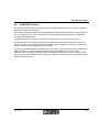
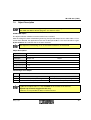
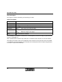
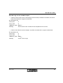
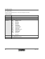
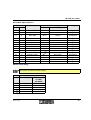
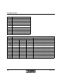
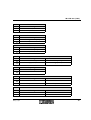
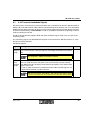
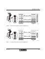
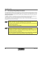
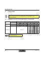
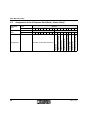
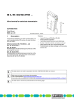
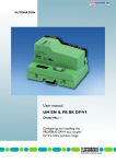
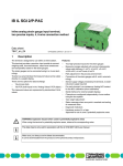
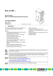
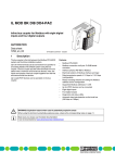
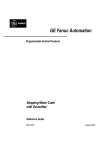
IB IL RS 232
IB IL RS 232-PAC
Inline Terminal
for Serial Data Transmission
Data Sheet
5 9 3 5 A 0 0 1
01/2005
The item versions only differ in the
scope of supply (see "Ordering Data"
on page 36). Their function and technical data are identical.
This data sheet is only valid in association with the "Configuring and Installing the INTERBUS Inline
IB IL SYS PRO UM E" user manual.
Function
The terminal is designed for use within an Inline
station. It enables the operation of off-the-shelf
I/O devices with serial interfaces on INTERBUS.
5 9 3 5 B 0 0 2
Features
–
A serial I/O channel (RS-232)
–
DTR/CTS handshake supported
–
Various protocols supported
–
Transmission speed adjustable
up to 38,400 baud
–
Number of data bits, stop bits, and parity can
be set
–
4-kbyte receive buffer and 1-kbyte transmit
buffer
–
Parameterization and data exchange via
INTERBUS using PCP services
–
Diagnostic and status indicators
5935_en_04
Figure 1
The terminal IB IL RS 232-PAC
1
IB IL RS 232 (-PAC)
Table of Contents
1 General Description .................................................................................................................. 3
2 Internal Circuit Diagram ............................................................................................................ 4
3 Connection Notes ...................................................................................................................... 6
4 Connection Examples ................................................................................................................ 6
4.1 Capacitor Between Shield and FE ................................................................................. 6
4.2 Shield Connected Directly to FE ................................................................................... 7
5 Programming Data/Configuration Data ..................................................................................... 7
5.1 INTERBUS..................................................................................................................... 7
5.2 Other Bus Systems ........................................................................................................ 7
6 Data Storage and Transmission ................................................................................................ 8
6.1 Overview of the Supported Protocols ........................................................................... 8
6.2 Transparent Protocol .................................................................................................... 9
6.3 End-to-End Protocol ...................................................................................................... 9
6.4 Dual Buffer Protocol....................................................................................................... 10
6.5 3964R Protocol .............................................................................................................. 10
6.6 XON/XOFF Protocol .....................................................................................................11
7 PCP Communication .................................................................................................................12
7.1 Object Dictionary............................................................................................................ 12
7.2 Object Description.......................................................................................................... 13
7.3 PCP Mode Error Messages ........................................................................................... 22
8 V.24 Interface
22
8.1 V.24 Terminal Handshake Signals.................................................................................23
8.2 V.24 Interface Wiring With Four-Wire Handshake ......................................................... 24
8.3 V.24 Interface Wiring Without Handshake ..................................................................... 26
9 Process Data.............................................................................................................................. 28
9.1 Assignment of the OUT Process Data Word (~Control Word)....................................... 28
9.2 Assignment of the OUT Process Data Word (~Control Word) ......................................29
9.3 Assignment of the IN Process Data Word (~Status Word) ............................................ 30
9.4 Format of the IN Process Data Word (~Status Word) ..................................................31
10 Technical Data ..........................................................................................................................33
11 Ordering Data ............................................................................................................................36
2
5935_en_04
IB IL RS 232 (-PAC)
1
General Description
Local Diagnostic and Status Indicators
D
T R
Des. Color Meaning
D
Green Bus diagnostics
TR
Green PCP active
Serial Interface:
RxD Yellow Terminal receives data from
the connected device
TxD Yellow Terminal transmits data to the
connected device
R x D
T x D
R S 2 3 2
Terminal Assignment
2
1
1
2
1 .1
1
1
2 .1
1 .2
2
2
2 .2
1 .3
3
3
2 .3
1 .4
4
4
2 .4
Connector
1
2
5 9 3 5 A 0 0 3
Figure 2
IB IL RS 232
with appropriate connectors
Application Examples
–
Scale with RS-232 interface
–
Label printer
–
PC interface (e.g., communication between
master and PC via INTERBUS)
–
Control of indication elements
–
Parameterization of intelligent field devices
(e.g., frequency inverter)
–
Transition to other protocols and media
(e.g., radio)
5935_en_04
Terminal
Point
1.4, 2.4
Signal
Assignment
FE
Functional earth
ground
All other terminal points of this connector
are not used.
1.1
RxD
Serial data input
2.1
TxD
Serial data output
1.2
+5 V
Control output,
internally wired to
+5 V DC
2.2
CTS
Control input for
hardware handshake
1.3
DTR
Control output for
hardware handshake
2.3
GND
GND for serial
interface
1.4, 2.4 Shield Shield connection
Observe the connection notes on
page 6.
3
IB IL RS 232 (-PAC)
2
Internal Circuit Diagram
IN T E R B U S
U
U
U
O P C
D
L +
A n a
L -
7 ,5 V
R x D
5 V
T R
T x D
5 V
5 V
1
µ P
R S -2 3 2
in te r fa c e
/
+ 2 4 V (U S )
R x D
R S -2 3 2
in te r fa c e
/
T x D
+ 5 V
C T S
+ 2 4 V (U M )
D T R
1
5 9 3 5 A 0 0 4
Figure 3
4
Internal wiring of the terminal points
5935_en_04
IB IL RS 232 (-PAC)
Key:
OPC
Protocol chip
Diagnostic and status indicators with function information
Optocoupler
DC/DC converter with electrical isolation
x x x
X X X
µ P
R S -2 3 2
In te rfa c e
Microprocessor
RS-232 interface
/
Capacitor
1
Ground, electrically isolated from ground of the potential jumper
Other symbols used are explained in the IB IL SYS PRO UM E user manual.
5935_en_04
5
IB IL RS 232 (-PAC)
3
Connection Notes
By assigning terminal points 1.4 and
2.4 of both connectors you can connect the cable shield either using a
capacitor (connector 2) or directly
(connector 1) to the functional earth
ground (FE).
4
Connection Examples
Use a connector with shield connection when installing the I/O device.
Figure 4 shows the connection schematically (without shield connector).
4.1
Using the two connection options you
can connect one side of the cable
shield directly and one side using a
capacitor to FE without additional effort. In this way, you can prevent the
creation of ground loops that would
occur if a shield with two direct connections were placed on FE.
If you connect the shield via
connector 1, you must connect the
shield connector on the left-hand side
of the terminal. All wires must be connected to connector 2.
Ensure that on connector 2, terminal
point 1.2 (+5 V) is exclusively used to
provide the 5 V signal for the CTS
input (terminal point 2.2), in the event
of communication without handshake. In this case insert a jumper between the terminal points.
Capacitor Between Shield and
FE
1
2
D
T R
R x D
T x D
R S 2 3 2
1
2
1
2
1
1 1
1
2
2 2
2
3
3 3
3
4
4 4
4
T x D
R x D
C T S
D T R
Any other use is not permitted.
5 9 3 5 A 0 0 5
Figure 4
Connection of an I/O device with a
serial interface
In this example the V.24 interface wiring for communication with 4-wire handshake is shown.
6
5935_en_04
IB IL RS 232 (-PAC)
4.2
Shield Connected Directly to
FE
1
2
D
T R
Programming Data/
Configuration Data
5.1
INTERBUS
ID code
DChex (220dec)
Length code
01hex
Process data channel
16 bits
Input address area
2 bytes
Output address area
2 bytes
R x D
T x D
R S 2 3 2
1
5
2
1
2
1 1
1
Parameter channel
(PCP)
4 bytes
1
2
2 2
2
Register length (bus)
6 bytes
3
3 3
3
4
4 4
4
Other Bus Systems
For the configuration data of other
bus systems, please refer to the appropriate electronic device data sheet
(GSD, EDS).
R x D
T x D
5.2
5 9 3 5 A 0 1 0
Figure 5
Connection of an I/O device with a
serial interface
In this example the V.24 interface wiring for communication without handshake is shown. You
should insert a jumper between connection
points 1.2 (+5 V) and 2.2 (CTS).
5935_en_04
7
IB IL RS 232 (-PAC)
6
Data Storage and Transmission
The IB IL RS 232 terminal stores the received V.24 data in an intermediate buffer, until it is fetched
from the V.24 interface by the INTERBUS controller board or the device.
V.24 data traffic can be managed using various protocols. The protocol used depends on the type of
protocol supported by the peer.
6.1
Overview of the Supported Protocols
Protocol
Receive Memory
Transmit Memory
Transparent
4096 bytes
1023 bytes
End-to-end
25 buffers each with
58 bytes
1023 bytes
(including
end characters)
Two end characters are
filtered out
Dual buffer
2 buffers each with
58 bytes
1023 bytes
(including
end characters)
Only stores the most
recently received data, end
characters are filtered out
3964R
25 buffers each with
58 bytes
15 buffers each with
58 bytes
Data exchange with software handshake, time
monitoring, and checksum
XON/XOFF
4096 bytes
1023 bytes
Software handshake
8
Special Features When
Receiving
5935_en_04
IB IL RS 232 (-PAC)
6.2
Transparent Protocol
If the transparent protocol is used, V.24 data is transmitted through the terminal in the same format
it was received from the V.24 or user side (INTERBUS side).
The transmit FIFO (First-In-First-Out memory) can store 1023 bytes (1 kbyte), and the receive FIFO
can store 4096 bytes (4 kbytes). If the terminal receives another character after the 4095th character,
the error pattern is stored in the receive FIFO. All other subsequent characters are ignored.
A CTS hardware handshake is supported with this protocol.
6.3
End-to-End Protocol
The V.24 data is conditioned for the end-to-end protocol.
If V.24 data is sent from the user side (INTERBUS side), two additional characters, the first and second delimiters, are attached for transmission to the V.24 side. The first and second delimiters are defined when the terminal is configured using the INIT-TABLE object.
V.24 data transmitted from the V.24 side can only be read by the user if the IB IL RS 232 terminal
has received the first and second delimiters. The two end characters confirm that the V.24 data has
been received without error and the maximum data length of 58 bytes has been observed. The delimiters are filtered out when the data is read by the INTERBUS side.
Unlike in the transparent protocol, the receive memory is not organized as a FIFO but as a buffer.
There are 25 buffers available, each with 58 bytes. If the buffer size of 58 bytes is exceeded, without
the two delimiters being detected, the buffer is overwritten again. Depending on the INIT-TABLE object, subindex 0Chex (rotation switch), there are two variants.
Variant 1 (0Chex = 0; default setting):
In the re-written buffer only the new data is available, i.e., data from the previous cycle is rejected.
Variant 2 (0Chex = 1): The buffer is re-written character by character. If the two delimiters are detected
the new characters and the remaining characters from the previous cycle are available in the rewritten buffer (rotation).
The transmit FIFO can store 1023 bytes. The delimiters are attached to, and stored with, the data to
be sent.
5935_en_04
9
IB IL RS 232 (-PAC)
6.4
Dual Buffer Protocol
With this protocol, the last received data block is stored. A data block is defined as a sequence of
V.24 characters with the first and second delimiter end characters, as in the end-to-end protocol.
As soon as a new data block is received, the previous one is overwritten. This is achieved by means
of two buffers, which are written alternately. This means that one buffer will always be available to
receive V.24 data, while the other will be storing the last received data block. A data block is only
regarded as complete once both delimiters have been detected, one after the other. It can then be
read from the INTERBUS side.
If the buffer size of 58 bytes is exceeded, without the two end characters (delimiters) being detected,
the buffer is overwritten again. Depending on the INIT-TABLE object, subindex 0Chex (rotation
switch), there are two variants.
Variant 1 (0Chex = 0): In the re-written buffer only the new data is available, i.e., data from the previous cycle is rejected.
Variant 2 (0Chex = 1): The buffer is re-written character by character. If the two delimiters are detected
the new characters and the remaining characters from the previous cycle are available in the rewritten buffer (rotation).
The same conditions as in the end-to-end protocol apply to transmitting V.24 data. If V.24 data is
transmitted from the user side (INTERBUS side), two additional characters, the first and second delimiters, are attached for transmission to the V.24 side.
6.5
3964R Protocol
This protocol, developed by Siemens, is the most complex. It uses beginning and end identifiers, a
checksum, and a time monitoring function.
There are 15 buffers available for transmission and 25 buffers for reception.
Character delay time:
220 ms
Acknowledgment delay time:
2s
Block waiting time:
10 s
Number of attempts to establish a connection:
6
The optional 3964 priority defines which device may transmit first (high priority) if there is an initialization conflict (several devices attempting to transmit data simultaneously).
10
5935_en_04
IB IL RS 232 (-PAC)
6.6
XON/XOFF Protocol
This protocol operates in the same way as the transparent protocol, but uses a software handshake
instead of a hardware handshake.
Data transmission with this protocol is controlled by the XON and XOFF characters. XON is preset to
11hex and XOFF to 13hex. These characters can also be defined when the terminal is configured
using the INIT-TABLE object.
If the terminal receives an XOFF, no more V.24 data will be sent until an XON is received.
The terminal itself will transmit an XOFF if the available space in the receive memory is less than
5 bytes. As soon as more memory becomes available again, the module will transmit a single XON.
The transmission does not depend on the CTS input.
V.24 data is not filtered when it is transmitted. Any characters, which occur with the code defined for
XON and XOFF, are thus transmitted and may trigger undesirable events at the receiver.
When V.24 data is received, the XON and XOFF characters are filtered and are not available as data.
Any characters with the XON or XOFF code are lost. Ensure that characters with these codes do not
appear in the data stream.
5935_en_04
11
IB IL RS 232 (-PAC)
7
PCP Communication
Information on PCP communication can be found in the "IBS SYS PCP G4 UM E" user
manual (Order No. 27 45 16 9).
By default upon delivery, the terminal is configured for data transmission according to the parameters
on page 17. The terminal can be configured to suit your application.
The terminal is configured in PCP mode using the "INIT-TABLE" object.
The programs IBS CMD (for standard controller boards) and IBS PC WORX (for Field
Controllers (FC) and Remote Field Controllers (RFC)) are available for the configuration
and parameterization of your INTERBUS system.
Additional information can be found in the "IBS CMD SWT G4 UM E" and "PC WORX 3
QS UM E" user manuals.
Parameter records and text strings are transmitted to or from a connected I/O device in PCP mode
using the "V24-DATA" object.
7.1
Object Dictionary
Index
Data Type
A
L
Meaning
Object Name
Rights
5FC1hex
Var of Unsigned 8
1
1
Module start indicator
START-IND
rd/wr
5FE0hex
String Var of Octet String
1
58
Transmit/receive
V.24 (RS-232) data
V24-DATA
rd/wr
5FFFhex
Array of Unsigned 8
20
1
Terminal
configuration
INIT-TABLE
rd/wr
N:
Number of elements
rd:
Read access permitted
L:
Element length in bytes
wr:
Write access permitted
12
5935_en_04
IB IL RS 232 (-PAC)
7.2
Object Description
In the tables for the value ranges of objects or elements, designations used in the
IBS CMD and IBS PC WORX programs are shown in italics.
START-IND Object
The object indicates whether or not the terminal was restarted.
After the voltage has been switched on (power up), the byte will always have a value of 01hex. For a
restart to be detected, the application must have set the byte to 00hex. If it is then set to 01hex again
by the terminal, this indicates that it has been restarted.
The object has no meaning as far as the terminal functions are concerned.
Object Description:
Object
START-IND
Access
Read, write
Data type
Simple Var
Index
5FC1hex
Subindex
00hex
Length (byte)
01hex
Data
Module start indicator
1 bytes
Value Range of the Object
Code
00hex
01hex
Module Start Indicator
Meaning
Representation in CMD/PC WORX
Reset power up message
Reset power up message
Power up completed
Power up completed
If you set the object to 01hex, it has no effect on the function of the terminal.
A power up cannot be triggered in this way.
However, it is not possible to detect a terminal restart.
5935_en_04
13
IB IL RS 232 (-PAC)
V24-DATA Object
This object is used for transmitting and receiving V.24 data.
Object Description:
Object
V24-DATA
Access
Read, write
Data type
String Var of Octet String
Index
5FE0hex
Subindex
00hex
(only access to all data possible)
Length (byte)
00hex
:
3Ahex
Amount of data present in the buffer
:
Maximum length of the object
Data
Transmit/receive V.24 data
1 x 58 bytes
If no V.24 data is available on a read access, a read response (read service reply) is generated with
result (+) and length = 0.
With a protocol data unit (PDU size) of 64 bytes a maximum of 58 characters can be transmitted.
The length of the read or write service depends on the number of V.24 characters to be transmitted.
If, for example, 20 V.24 characters are to be read, the read response will be 24 bytes long (20 bytes
V.24 data + 4 bytes PCP overhead).
14
5935_en_04
IB IL RS 232 (-PAC)
Error Messages for the V24-DATA Object:
–
If, during a write service, there is not enough transmit memory available for V.24 data, the service
will be answered with a negative confirmation.
The parameters are:
Error_Class
8
Error_Code
0
Additional_Code
0022hex
Meaning
No character of the V.24 data will be accepted from this service
–
A write service without user data (length = 0) will be answered with a negative confirmation.
The parameters are:
Error_Class
8
Error_Code
0
Additional_Code
0030hex
Meaning
Value is out of range
5935_en_04
15
IB IL RS 232 (-PAC)
INIT-TABLE Object
Writing the INIT-TABLE object with a write service configures the terminal.
Object Description
Object
INIT-TABLE
Access
Read, write
Data type
Array of Unsigned 8
Index
5FFFhex
Subindex
00hex
01hex
02hex
03hex
04hex
05hex
06hex
07hex
08hex
09hex
0Ahex
0Bhex
0Chex
0Dhex
0Ehex
0Fhex
:
14hex
Length (byte)
14hex Subindex 00hex
01hex Subindex 01hex to 14hex
Data
Configuration of the IB IL RS 232 terminal
16
20 x 1 bytes
Write all elements
Protocol
Baud rate
Data width
Reserved
Reserved
Error pattern
First delimiter
Second delimiter
3964R priority
Output type
DTR control system
Rotation switch
XON pattern
XOFF pattern
Reserved
:
Reserved
5935_en_04
IB IL RS 232 (-PAC)
INIT-TABLE Object Elements
Element
dec
hex
1
1
2
2
Meaning
Protocol
Baud rate
Code
00hex
07hex
3
3
Data width
02hex
4
5
6
7
8
9
10
11
12
13
14
15-20
4
5
6
7
8
9
A
B
C
D
E
F-14
Reserved
Reserved
Error pattern
First delimiter
Second delimiter
3964R priority
Output type
DTR control system
Rotation switch
XON pattern
XOFF pattern
Reserved
00hex
00hex
24hex
0Dhex
0Ahex
00hex
00hex
00hex
00hex
11hex
13hex
00hex
Default Setting
Meaning
Transparent
9600 baud
8 data bits, even parity, 1
stop bit
($)
Carriage Return (CR)
Line Feed (LF)
Low
RS 232
Automatic
No rotation
Data Type
Unsigned 8
Unsigned 8
Unsigned 8
Unsigned 8
Unsigned 8
Unsigned 8
Unsigned 8
Unsigned 8
Unsigned 8
Unsigned 8
Unsigned 8
Unsigned 8
Unsigned 8
Unsigned 8
Unsigned 8
Element Value Range
The options in bold are default settings.
Code
00hex
01hex
02hex
03hex
04hex
5935_en_04
Protocol (Protocol)
Meaning
Representation
in CMD/
PC WORX
Transparent
Transparent
End-to-end
End-End
Dual buffer
Dual buffer
3964R
3964R
XON/XOFF
XON/XOFF
17
IB IL RS 232 (-PAC)
Code
00hex
01hex
02hex
03hex
04hex
05hex
06hex
07hex
08hex
09hex
Baud Rate (Baud Rate)
Value
110
300
600
1200
1800
2400
4800
9600
19200
38400
Code
00hex
01hex
02hex
03hex
04hex
05hex
06hex
07hex
08hex
09hex
0Ahex
0Bhex
18
Data Bits
7
7
8
8
8
7
7
7
8
8
8
7
Meaning
Parity
Even
Odd
Even
Odd
Without
Without
Even
Odd
Even
Odd
Without
Without
Data Width (Data Width)
Representation in CMD/PC WORX
Stop Bits
1
7 data bits, even parity, 1 stop bit
1
7 data bits, odd parity, 1 stop bit
1
8 data bits, even parity, 1 stop bit
1
8 data bits, odd parity, 1 stop bit
1
8 data bits, without parity, 1 stop bit
1
7 data bits, without parity, 1 stop bit
2
7 data bits, even parity, 2 stop bits
2
7 data bits, odd parity, 2 stop bits
2
8 data bits, even parity, 2 stop bits
2
8 data bits, odd parity, 2 stop bits
2
8 data bits, without parity, 2 stop bits
2
7 data bits, without parity, 2 stop bits
5935_en_04
IB IL RS 232 (-PAC)
Code
24hex
xxhex
Error Pattern
Meaning
$
Any character
Code
0Dhex
xxhex
First Delimiter
Meaning
Carriage return (CR)
Any character
Code
0Ahex
xxhex
Second Delimiter
Meaning
Line Feed (LF)
Any character
Code
00hex
01hex
Meaning
Low Priority
High priority
Code
00hex
Output Type
Meaning
RS-232
Code
00hex
01hex
Code
00hex
01hex
5935_en_04
Meaning
Automatic
Via process data
Meaning
No rotation
Rotation
3964R Priority
Representation in CMD/PC WORX
Low priority
High priority
DTR Control
Representation in CMD/PC WORX
Automatic
Via process data
Rotation Switch
Representation in CMD/PC WORX
No rotation
Rotation
19
IB IL RS 232 (-PAC)
Code
11hex
xxhex
Code
13hex
xxhex
XON Pattern
Meaning
Any character
(not the same as XOFF pattern)
XOFF Pattern
Meaning
Any character
(not the same as XON pattern)
The error pattern contains the character that is written to the FIFO if a V.24 character was received
with errors (this does not apply to the 3964R protocol). This can be the result of, for example, parity
errors, exceeded value ranges or noise interference. In the transparent and XON/XOFF protocols,
the pattern is also used if the receive FIFO is full and further characters are received.
The first delimiter and the second delimiter contain the end characters for the dual buffer and the
end-to-end protocols.
The value in the 3964R priority element defines the priority of a device if there is an initialization conflict (more than one device attempting to transmit data simultaneously). The device with priority level
1has priority over the device with priority level 0.
XON pattern and XOFF pattern contain the control characters for the XON/XOFF protocol The
characters must not be the same.
The rotation switch determines how the buffer is re-written when it is full and the two end characters
(delimiters) have not been detected.
No rotation:
In the re-written buffer only the new data is available, i.e., data from the previous cycle is rejected.
Rotation:
The buffer is re-written character by character. If the two delimiters are detected the new characters
and the remaining characters from the previous cycle are available in the re-written buffer.
If at least one element of the INIT-TABLE object is written, the pointers for the transmit and
receive FIFOs will be reset. This means that all transmit and receive data that has not yet
been processed is lost.
20
5935_en_04
IB IL RS 232 (-PAC)
INIT-TABLE Object Error Messages
–
If an element with an invalid value is written during a write service, the service will be
acknowledged with a negative confirmation.
The parameters are:
Error_Class
8
Error_Code
0
Additional_Code
xx30hex
Meaning
Value is out of range
The high byte of the ADDITIONAL_CODE (xx) contains the number of the affected element. If several
elements are affected, the highest number is given. If, for example, the DTR control element is written
with the value 2, an error message with the ADDITIONAL_CODE 0B30hexwill be displayed, because
the 11th element is faulty.
–
An error message will be generated for a write request with the subindex 0 (write entire table) in
which the XON/XOFF protocol is to be set and the XON pattern is the same as the XOFF pattern.
The parameters are:
Error_Class
8
Error_Code
0
Additional_Code
0E30hex
Meaning
Parameterization error
–
If a reserved element is written, the value must equal 0, otherwise an error message is generated.
The parameters are:
Error_Class
8
Error_Code
0
Additional_Code
xx30hex
Meaning
Parameterization error
5935_en_04
21
IB IL RS 232 (-PAC)
7.3
PCP Mode Error Messages
The terminal error messages have parameters
Error_Class = 8 (device-specific error) and Error_Code = 0 (no communication error).
The precise error cause is indicated via the Additional_Code. The low byte of the
ADDITIONAL_CODE specifies the error cause. The high byte of the ADDITIONAL_CODE (xx)
contains the number of the affected element. If several elements are affected, the highest number is
given.
The following ADDITIONAL_CODEs can occur on this terminal:
0022hex
No character of the V.24 (RS-232) data will be accepted
from this service
xx30hex
Value is out of range or parameterization error
0000hex
Hardware fault
For additional information on error messages in PCP mode, please refer to the
IBS SYS PCP G4 UM E user manual
(Order No. 27 45 16 9) and your controller board user manual.
8
V.24 Interface
The V.24 (RS-232) interface on the IB IL RS 232 terminal represents some form of DTE (data termination equipment). This means that connector 2 terminal point 2.1 (TxD) is always used to transmit
and connector 2 terminal point 1.1 (RxD) is always used to receive.
According to the standard, some form of DCE (data communication equipment) is connected to the
V.24 interface as a peer. DTE can also be connected. Please refer to the connection notes under 8.2
and 8.3.
Measuring the voltage between the connection points for the TxD and GND signals in idle state will
determine whether the device to be connected to the V.24 interface is a form of DTE or DCE. If the
voltage measures approximately -5 V, the device is a form of DTE. If the voltage is approximately 0 V,
the device is a form of DCE.
Example: When using a 25-pos. standard connector (see Figure 5 on page 7) the voltage between
pin 2 (TxD) and pin 7 (GND) must be measured.
22
5935_en_04
IB IL RS 232 (-PAC)
8.1
V.24 Terminal Handshake Signals
Any device with a V.24 interface can be connected to the V.24 interface on the IB IL RS 232 terminal.
Both the IB IL RS 232 terminal and the device connected to the V.24 interface can act as transmitter
and receiver for data exchange. As errors can occur during data exchange if both devices transmit
or receive simultaneously, the handshake is used as a procedure for the mutual signaling of clear to
receive and clear to transmit.
The IB IL RS 232 terminal supports DTR and CTS handshake signals. Each uses one wire of the
connecting cable.
The connecting signals are described from the point of view of the IB IL RS 232 terminal, i.e., from
the point of view of the DTE.
Handshake signals:
Signal
Meaning
Direction
CTS
The IB IL RS 232 terminal receives the CTS signal from the connected device Input
(Clear To via the V.24 interface. If the CTS signal is set to High, the terminal can transmit
Send)
data.
The exception is 3964R, XON/XOFF Protocol
DTR
(Data
Terminal
Ready)
The DTR signal is transmitted from the IB IL RS 232 terminal, i.e., set to High, Output
once it is ready to receive. The peer at the V.24 interface can now transmit.
After 4095 characters (4 kbytes) the terminal receive buffer is full, and the DTR
signal is set to Low.
As soon as more characters are read from the bus side, the DTR signal is set
to High and the terminal is ready to receive.
With the transparent, XON/XOFF, and end-to-end protocols, DTR
is set to "0" if fewer than 15 characters are free in the receive FIFO.
5935_en_04
23
IB IL RS 232 (-PAC)
8.2
V.24 Interface Wiring With Four-Wire Handshake
The TxD, RxD, DTR, and CTS signals are used for a four-wire handshake connection between the
IB IL RS 232 terminal and the device to be connected. Each signal corresponds to one wire in the
connecting cable. An Inline male connector is required on the IB IL RS 232 terminal side.
A 9 or 25-pos. socket is required on the opposite side depending on the device to be connected.
Both GND pins are also wired.
In Figure 6 and Figure 7 the shield connector is connected on the right-hand side of the
terminal. In this case, a capacitor is placed between the shield and FE.
If the shield is to be placed directly on FE, the shield connector must be connected on the
left-hand side of the terminal.
Observe the connection notes on page 6.
In Figure 6 and Figure 7 it is assumed that the signal assignment of the connectors for the
device to be connected corresponds to the assignment of a PC connector.
In individual cases, however, the signal assignment of the pins might be different because
the DTE-DTE connections as well as the connections between 25-pos. and 9-pos. connectors and sockets are not standardized.
24
5935_en_04
IB IL RS 232 (-PAC)
2
1
IB IL R S 2 3 2
1
2
1 .1
1
1
2 .1
1 .2
2
2
2 .2
1 .3
3
3
2 .3
1 .4
4
4
2 .4
T x D
2 .1
2
T x D
R x D
1 .1
3
R x D
+ 5 V
1 .2
4
R T S
C T S
2 .2
5
C T S
D T R
1 .3
2 0
D T R
G N D
2 .3
7
G N D
In lin e c o n n e c to r
(c o n n e c to r 2 )
Figure 6
1
D T E d e v ic e ( e .g ., P C )
1 4
1
2 5
1 3
S o ld e r
s id e
2 5 -p o s . D -S U B
s o c k e t
5 9 3 5 A 0 0 8
V.24 interface wiring with handshake for DTE (25-pos.)
2
IB IL R S 2 3 2
1
1 .1
2
1
2 .1
1
1 .2
2
2
2 .2
1 .3
3
3
2 .3
4
4
2 .4
1 .4
T x D
2 .1
3
T x D
R x D
1 .1
2
R x D
+ 5 V
1 .2
7
R T S
C T S
2 .2
8
C T S
D T R
1 .3
4
D T R
G N D
2 .3
5
G N D
In lin e c o n n e c to r
(c o n n e c to r 2 )
Figure 7
5935_en_04
D T E d e v ic e ( e .g ., P C )
6
9 -p o s . D -S U B
s o c k e t
9
1
5
S o ld e r
s id e
5 9 3 5 A 0 1 2
V.24 interface wiring with handshake for DTE (9-pos.)
25
IB IL RS 232 (-PAC)
8.3
V.24 Interface Wiring Without Handshake
For wiring without handshake, the transmission can only be executed with the help of both TxD and
RxD signals. Both wires for the TxD and RxD signals, in the same way as the GND contacts, are connected to the IB IL RS 232 terminal male connector and are soldered to the socket on the side of the
device to be connected.
In addition, a jumper is connected on the male connector between the terminal points for the +5 V
and CTS signals and on the socket between the pins for the RTS and CTS signals.
This simulates the constant ready to receive state of the peer, and the connected device will always
be able to transmit via the V.24 interface.
In Figure 8 and Figure 9 the shield connector is connected on the right-hand side of the
terminal. In this case, a capacitor is placed between the shield and FE.
If the shield is to be placed directly on FE, the shield connector must be connected on the
left-hand side of the terminal.
Observe the connection notes on page 6.
In Figure 8 and Figure 9 it is assumed that the signal assignment of the connectors for the
device to be connected corresponds to the assignment of a PC connector.
In individual cases, however, the signal assignment of the pins might be different because
the DTE-DTE connections as well as the connections between 25-pos. and 9-pos. connectors and sockets are not standardized.
The terminal sets the DTR signal to Low before the receive FIFO overflows. As the DTR
signal is not evaluated for wiring without handshake, some of the data sent to the terminal
via the V.24 interface may be lost until the terminal is ready to receive again.
26
5935_en_04
IB IL RS 232 (-PAC)
2
1
IB IL R S 2 3 2
1
2
D T E d e v ic e ( e .g ., P C )
T x D
2 .1
2
T x D
R x D
1 .1
3
R x D
1 .1
1
1
2 .1
+ 5 V
1 .2
4
R T S
1 .2
2
2
2 .2
C T S
2 .2
5
C T S
1 .3
1 .3
2 0
D T R
3
2 .3
D T R
3
G N D
2 .3
7
G N D
1 .4
2 .4
4
4
In lin e c o n n e c to r
(c o n n e c to r 2 )
1 4
1
2 5
1 3
S o ld e r
s id e
2 5 -p o s . D -S U B
s o c k e t
5 9 3 5 A 0 0 9
Figure 8
1
V.24 interface wiring without handshake for DTE (25-pos.)
2
IB IL R S 2 3 2
1
2
D T E d e v ic e ( e .g ., P C )
T x D
2 .1
3
T x D
R x D
1 .1
2
R x D
6
1 .1
1
1
2 .1
+ 5 V
1 .2
7
R T S
1 .2
2
2
2 .2
C T S
2 .2
8
C T S
D T R
1 .3
4
D T R
G N D
2 .3
5
G N D
1 .3
3
3
2 .3
1 .4
4
4
2 .4
In lin e c o n n e c to r
(c o n n e c to r 2 )
1
9
5
S o ld e r
s id e
9 -p o s . D -S U B
s o c k e t
5 9 3 5 A 0 1 3
Figure 9
5935_en_04
V.24 interface wiring without handshake for DTE (9-pos.)
27
IB IL RS 232 (-PAC)
9
Process Data
For the assignment of the illustrated (byte.bit) view under 9.1 and 9.3 to your control or
computer system, please refer to the DB GB IBS SYS ADDRESS data sheet,
Order No. 90 00 99 0.
Assignment of the OUT Process Data Word (~Control Word)
7
6
5
7
5
4
3
2
1
0
2
1
0
Byte 1
2
1
0
7
6
5
4
Reserved
DTR
Assignment
6
3
3
Reserved
Byte 0
4
Reset receive error
Bit
8
Reset transmit error
Byte
15 14 13 12 11 10 9
Execute re-initialization
(Byte.bit)
view
Bit
Word 0
Reserved
Word
Reserved
(Word.bit)
view
Reserved
9.1
Set all reserved bits to 0.
28
5935_en_04
IB IL RS 232 (-PAC)
9.2
Assignment of the OUT Process Data Word (~Control Word)
P C P c h a n n e l
P C P c h a n n e l
P ro c e s s d a ta c h a n n e l
M S B
1 5
L S B
1 4
1 3
1 2
1 1
1 0
9
8
7
6
5
D T R
0
4
3
2
1
0
0
0
0 : lo g ic ` 0 `
1 : lo g ic ` 1 `
R e c e iv e e r r o r
0 : N o a c tio n
1 : R e s e t r e c e iv e e r r o r
T r a n s m it e r r o r
0 : N o a c tio n
1 : R e s e t tr a n s m it e r r o r
R e - in itia liz a tio n
0 : N o a c tio n
1 : C a r r y o u t r e - in itia liz a tio n
5 9 3 5 A 0 0 7
Figure 10 Format of the OUT process data word in the INTERBUS ring
The DTR signal can only be generated when "DTR control via process data" is enabled.
If the control word has the contents 3C00hex, then the status word returns the firmware version.
Example:
Status word (hex)
1
2
Firmware version 1.23
5935_en_04
3
0
0
29
IB IL RS 232 (-PAC)
Assignment of the IN Process Data Word (~Status Word)
15 14 13 12 11 10 9
30
6
5
6
5
4
3
2
1
0
2
1
0
Byte 1
2
1
0
7
Number of received characters
6
5
4
3
Receive buffer not empty
7
3
Receive error
Byte 0
4
Transmit error
Bit
7
Re-initialization executed
Byte
8
Reserved
Assignment
Bit
Word 0
Receive buffer full
(Byte.bit)
view
Word
Send buffer full
(Word.bit)
view
Send buffer not empty
9.3
5935_en_04
IB IL RS 232 (-PAC)
9.4
Format of the IN Process Data Word (~Status Word)
P C P c h a n n e l
P C P c h a n n e l
P ro c e s s d a ta c h a n n e l
M S B
1 5
L S B
1 4
1 3
1 2
1 1
1 0
9
O n ly w ith tr a n s p a r e n t a n d X O N /X O F F
N u m b e r o f r e c e iv e d V .2 4 c h a r a c te r s
If v a lu e = F F h e x , th e n th e n u m b e r
> = 2 5 5 c h a ra c te rs
8
7
6
5
4
3
2
1
R e s e rv e d
0
R e c e iv e b u ffe r
0 : E m p ty
1 : N o t e m p ty
T r a n s m it b u ffe r
R e c e iv e e r r o r
0 : E m p ty
1 : N o t e m p ty
0 : N o e rro r
1 : E rro r
T r a n s m it b u ffe r
T r a n s m it e r r o r
0 : N o t fu ll
1 : F u ll
0 : N o e rro r
1 : E rro r
R e c e iv e b u ffe r
R e - in itia liz a tio n
0 : N o t fu ll
1 : F u ll
0 : N o r e - in itia liz a tio n
1 : R e - in itia liz a tio n c o m p le te
5 9 3 5 A 0 0 6
Figure 11 Format of the IN process data word in the INTERBUS ring
5935_en_04
31
IB IL RS 232 (-PAC)
Bit/Status Effect
Protocol
Bit 0 = '1'
The receive buffer is not empty, characters to be read are available.
All
Bit 1 = '1'
The receive error indicates that a 3964R telegram could not be received 3964R
without error after six transmit attempts by the V.24 peer or after the
block waiting time had elapsed.
Bit 2 = '1'
The transmit error indicates that a 3964R telegram could not be trans- 3964R
mitted from the module to the V.24 peer without error after six transmit
attempts. The telegram was rejected.
Bit 3 = '1'
A re-initialization was executed; transmit and receive buffers are now
empty.
All
Bit 4 = '1'
The receive buffer is full:
Transparent and XON/XOFF protocol:Residual capacity:
< 15 characters
3964R and end-to-end protocol:Residual capacity: none
Transparent,
end-to-end,
3964R,
XON/XOFF
Bit 5 = '1'
The transmit buffer is full:
3964R protocol:Residual capacity: none
Dual buffer, transparent,
end-to-end, XON/XOFF protocol:Residual capacity:
≤30 characters
All
Bit 6 = '1'
The transmit buffer is not empty, characters to be sent are available.
All
Bit 7 = '1'
Reserved
Both error bits (bit 1 and 2) are not automatically reset. They can only be reset by the OUT
process data word.
32
5935_en_04
IB IL RS 232 (-PAC)
10
Technical Data
General Data
Order Designation (Order No.)
IB IL RS 232
IB IL RS 232-PAC
(27 27 34 9)
(28 61 35 7)
Housing dimensions (width x height x depth)
24.4 mm x 120 mm x 71.5 mm
Weight
90 g (without connectors), 128 g
(including connectors)
Mode
Process data mode with 1 word
PCP mode with two words
Permissible temperature (operation)
-25°C to +55°C
Permissible temperature (storage/transport)
-25°C to +85°C
Permissible humidity (operation)
75% on average, 85% occasionally
In the range from - 25°C to + 55°C appropriate measures against increased humidity
(> 85%) must be taken.
Permissible humidity (storage/transport)
75% on average, 85% occasionally
For a short period, slight condensation may appear on the outside of the housing if, for
example, the terminal is brought into a closed room from a vehicle.
Permissible air pressure (operation)
80 kPa to 106 kPa
(up to 2,000 m above sea level)
Permissible air pressure (storage/transport)
70 kPa to 106 kPa
(up to 3,000 m above sea level)
Degree of protection
IP20 according to IEC 60529
Class of protection
Class 3 according to VDE 0106, IEC 60536
The terminals must be installed in closed metal control cabinets so that the operation
meets the requirements of the Schifffahrtsklassifikations-Gesellschaft (GL).
5935_en_04
33
IB IL RS 232 (-PAC)
Interfaces
INTERBUS
Local bus
Through data routing
Serial RS-232 Interface
Type
V.24 (RS-232) interface with DTR/CTS handshake
Data terminal equipment (DTE) version
Electrical data according to EIA (RS) 232,
CCITT V.28, DIN 66259 Part 1
Input impedance
5 kΩ typical
Permissible input voltage area
-30 V to +30 V
Switching thresholds
0.8 V to 2.4 V
Hysteresis
0.5 V, typical
Output voltage "HIGH" (with 3 kΩ load)
6.7 V, typical
Output voltage "LOW" (with 3 kΩ load)
-6.7 V, typical
Output voltage "HIGH" (no-load operation)
≤ 25 V
Output voltage "LOW" (no-load operation)
≥ -25 V
Permissible load capacity
2500 pF
Short-circuit protected against GND
Yes
Short-circuit current
±60 mA, maximum
Power Consumption
Communications power UL
7.5 V
Current consumption at UL
155 mA, typical; 225 mA, maximum*
Total power consumption
Approx. 1.163 W, typical, 1.688 W, max.*
* All serial interface connections short circuited.
This terminal takes no current from the UM and US potential jumpers.
Supply of the Module Electronics Through the Bus Terminal
Connection method
34
Potential routing
5935_en_04
IB IL RS 232 (-PAC)
Power Dissipation
Power dissipation in the module
PEL = 1.163 W
Power dissipation of the housing PHOU
1.2 W, max.
(within the permissible operating temperature)
Limitation of Simultaneity, Derating
No limitation of simultaneity, no derating
Safety Equipment
None
Electrical Isolation / Isolation of the Voltage Areas
Electrical isolation of the logic level from the serial interface is ensured by the
DC/DC converter.
Common Potentials
The serial interface control and data lines have galvanically the same potential.
FE is a separate potential area.
Separate Potentials in the System Consisting of Bus Terminal/Power Terminal
and I/O Terminal
- Test Distance
- Test Voltage
5 V supply incoming remote bus / 7.5 V supply (bus logic)
500 V AC, 50 Hz, 1 min
5 V supply outgoing remote bus / 7.5 V supply (bus logic)
500 V AC, 50 Hz, 1 min
RS-232 interface / 7.5 V supply (bus logic)
500 V AC, 50 Hz, 1 min
RS-232 interface / 24 V supply (I/O)
500 V AC, 50 Hz, 1 min
RS-232 interface / functional earth ground
500 V AC, 50 Hz, 1 min
7.5 V supply (bus logic) / 24 V supply (I/O)
500 V AC, 50 Hz, 1 min
7.5 V supply (bus logic) / functional earth ground
500 V AC, 50 Hz, 1 min
24 V supply (I/O) / functional earth ground
500 V AC, 50 Hz, 1 min
Error Messages to the Superior Control System
None
5935_en_04
35
IB IL RS 232 (-PAC)
11
Ordering Data
Description
Order Designation
Order No.
Inline terminal for serial data transmission including IB IL RS 232-PAC
connectors and labeling field
28 61 35 7
Inline terminal for serial data transmission
27 27 34 9
IB IL RS 232
Two connectors are needed for the complete fitting of the IB IL RS 232 terminal.
These are included in the connector set listed below.
Connector set with a standard connector and a
shield connector
pack of 1 set
IB IL AO/CNT-PLSET
27 32 66 4
"Configuring and Installing the INTERBUS Inline
Product Range" user manual
IB IL SYS PRO UM E
27 43 04 8
© PHOENIX CONTACT 01/2005 Technical modifications reserved. 90 04 10 3
Make sure you always use the latest documentation. It can be downloaded at
www.download.phoenixcontact.com.
A conversion table is available on the Internet at
www.download.phoenixcontact.com/general/7000_en_00.pdf.
PHOENIX CONTACT GmbH & Co. KG
Flachsmarktstr. 8
32825 Blomberg
Germany
+ 49 - (0) 52 35 - 3-00
+ 49 - (0) 52 35 - 3-4 12 00
www.phoenixcontact.com
Worldwide Locations:
www.phoenixcontact.com/salesnetwork
36
5935_en_04