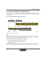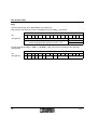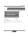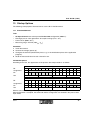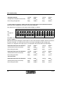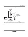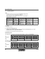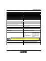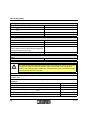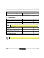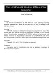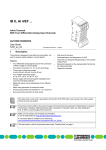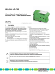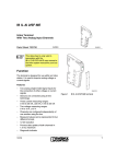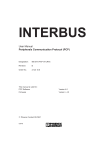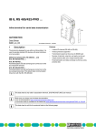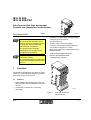
1
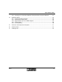
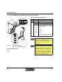
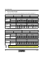
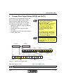
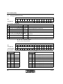
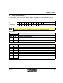
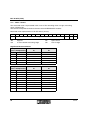
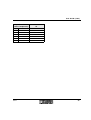
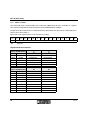
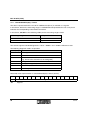
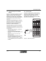
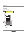
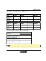
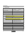
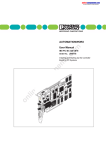
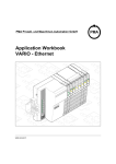
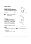
IB IL AI 8/IS
IB IL AI 8/IS-PAC
Inline Terminal With Eight Analog Input
Channels and a Supply for Passive Sensors
Data Sheet 6321B
03/2003
–
Provision of a short-circuit protected supply
voltage for passive sensors
(UiS; default 24 V)
–
Various current measuring ranges
–
Channels are configured independently of
one another using the bus system
For greater clarity, the Order
Designation IB IL AI 8/IS is used
throughout this document.
–
Measured values can be represented in five
different formats
–
16-bit analog-to-digital converter
This data sheet is only valid in
association with the
IB IL SYS PRO UM E User Manual or
the Inline System Manual for your bus
system.
–
Process data multiplex mode
–
LED diagnostic indicators
The IB IL AI 8/IS and
IB IL AI 8/IS-PAC only differ in the
scope of supply (see "Ordering Data"
on page 45). Their function and
technical data are identical.
1
6 3 2 1 B 0 0 1
Function
The terminal is designed for use within an Inline
station. It is used to detect analog current signals
from active and passive sensors.
1.1
Features
–
Eight analog single-ended signal inputs for
the connection of active and passive current
sensors
–
Connection of sensors in 2 and 3-wire
technology
6 3 2 1 B 0 0 2
Figure 1
6321B
IB IL AI 8/IS terminal
with connector
1
IB IL AI 8/IS (-PAC)
Table of Contents
1
Function .................................................................................................................................. 1
1.1 Features........................................................................................................................ 1
1.2 Local LED Diagnostic Indicators and Terminal Assignment ......................................... 4
2
Installation Instructions ........................................................................................................... 5
3
Internal Circuit Diagram .......................................................................................................... 6
4
Electrical Isolation .................................................................................................................. 7
5
Connection Notes ................................................................................................................... 7
6
Connection Examples ............................................................................................................. 8
6.1 Connection of Active Sensors....................................................................................... 8
6.2 Connection of Passive Sensors .................................................................................... 8
6.3 Connection of Several Analyzing Units......................................................................... 9
7
Programming Data/Configuration Data................................................................................... 9
7.1 INTERBUS.................................................................................................................... 9
7.2 Other Bus Systems ....................................................................................................... 9
8
Process Data Words .............................................................................................................10
8.1 Process Data Output Words for the Configuration of the Terminal (see page 11) ..... 10
8.2 Process Data Input Words (see page 15)................................................................... 10
9
Process Data Output Words OUT[0] and OUT[1] ................................................................. 11
9.1 OUT[0] (Command Code)........................................................................................... 12
9.2 OUT[1] (Parameter Word) .......................................................................................... 13
10
Process Data Input Words IN[0] and IN[1]............................................................................ 15
10.1 IN[0] and IN[1] for Commands 0x00hex to 6000hex ................................................................... 15
10.2 IN[0] and IN[1] for the Group Commands 7x00hex .................................................................... 18
11
Formats for Representation of Measured Values ................................................................. 20
11.1 "IB IL" Format.............................................................................................................. 20
11.2 "IB ST" Format ............................................................................................................ 22
11.3 "IB RT" Format............................................................................................................ 24
11.4 "Standardized Display" Format ...................................................................................26
11.5 Examples of Measured Value Representation in Various Data Formats.................... 28
11.6 "PIO" Format............................................................................................................... 29
12
Process Data Input Words in the Event of an Error .............................................................. 30
13
Startup Options ..................................................................................................................... 31
13.1 Standard Method 1 ..................................................................................................... 31
13.2 Standard Method 2 ..................................................................................................... 34
13.3 Special Methods ......................................................................................................... 37
2
6321B
IB IL AI 8/IS (-PAC)
13.4 Advantages of the Standard Methods Compared With the Special Methods............. 37
14
Application Notes .................................................................................................................. 38
14.1 Precision DC Measurements ...................................................................................... 38
14.2 Closed-Loop Control Tasks ........................................................................................ 38
14.3 Signal Scanning or Fast, Sudden Signals .................................................................. 39
14.4 Current Loops ............................................................................................................. 39
14.5 Passive Sensors ......................................................................................................... 40
15
Tolerance and Temperature Response ................................................................................ 41
16
Technical Data ...................................................................................................................... 42
17
Ordering Data ....................................................................................................................... 45
6321B
3
IB IL AI 8/IS (-PAC)
1.2
Local LED Diagnostic Indicators and Terminal Assignment
Local LED Diagnostic Indicators
D
U iS
A I8 IS
Des.
Color
Meaning
D
Green
Diagnostics
UiS
Green
Initiator supply
ON
Initiator supply present
Flashing Overload/short circuit of the
...
initiator supply at:
1
2
1 .1
1
1
2 .1
1 .2
2
2
2 .2
1 .3
3
3
2 .3
1 .4
4
4
2 .4
... 1x
Slot 1
... 2x
Slot 2
... 3x
Slot 3
... 4x
Slot 4
or
Supply voltage UiS not present
If the initiator supply fails, the LED of
the relevant slot number starts
flashing. This is followed by a long
pause after which the flashing
resumes.
6 3 2 1 B 0 0 3
Figure 2
IB IL AI 8/IS terminal
with an appropriate connector
Function Identification
Green
4
If the UiS LED flashes four times,
check the UM LED on the preceding
power terminal. If the cause of the
flashing is not an error at slot 4, but
the failure of the supply voltage UiS,
the UM LED signals the failure of the
supply voltage UM to the preceding
power terminal (UM LED off).
6321B
IB IL AI 8/IS (-PAC)
Terminal Assignment for Each Connector
Terminal Signal
Points
Assignment
1.1
+UiS1
Initiator supply channel 1
2.1
+UiS2
Initiator supply channel 2
1.2
+I1
Current input channel 1
2.2
+I2
Current input channel 2
1.3, 2.3
-1, -2
Minus input
1.4, 2.4
Shield
Shield connection
2
Installation Instructions
High current flowing through potential jumpers UM and US causes the temperature of the potential
jumpers and the internal temperature of the terminal to increase. Observe the following instructions
to keep the current flowing through the potential jumpers of the analog terminals as low as possible:
Create a separate main circuit for each analog terminal.
If this is not possible in your application and you are using analog terminals in a main
circuit together with other terminals, place the analog terminals behind all the other
terminals at the end of the main circuit.
6321B
5
IB IL AI 8/IS (-PAC)
3
Internal Circuit Diagram
L o c a l b u s
U
O P C
L +
A N A
L -
U
U
2 4 V
µ P
+- 5 V
E E P R O M
R E F
S U P E R V IS O R
M U X
4
4
2
2
IS 1
U
U
IS 2
IS 2
U
U
IS 3
IS 3
U
E L F
U
IS 1
E L F
E L F
U
2
E L F
2
U
IS 4
IS 4
+ 2 4 V (U S )
I IN
+ 2 4 V (U M )
1
I IN
2
I IN
3
I IN
4
I IN
5
I IN
6
I IN
7
I IN
8
1
6 3 2 1 B 0 0 4
Figure 3
Internal wiring of the terminal points
Key:
OPC
µ P
Analog-to-digital converter
Optocoupler
Amplifier
Microprocessor
E E P R O M
Electrically erasable
programmable read-only memory
S U P E R V IS O R
Microprocessor monitoring
x x x
X X X
R E F
6
Protocol chip
Power supply unit with electrical
isolation
M U X
E L F
Multiplexer
Electronic fuse
Other symbols are explained in the
IB IL SYS PRO UM E User Manual
or in the Inline System Manual for
your bus system.
Reference voltage source
6321B
IB IL AI 8/IS (-PAC)
4
Electrical Isolation
L o c a l b u s (IN )
U
L
U
O P C b u s
in te r fa c e a n d
m ic r o p r o c e s s o r
(7 .5 V D C )
A N A
(2 4 V D C )
L
U
(7 .5 V D C )
A N A
(2 4 V D C )
A
+ 5 V
-
F E p o te n tia l
5
U
2 4 V
+ 5 V
-
Figure 4
L o c a l b u s (O U T )
I/O
in te r fa c e
A n a lo g in p u ts
B
E le c tr ic a l is o la tio n
b e tw e e n a re a
A a n d B
6 3 2 1 A 0 0 9
Electrical isolation of the individual
function areas
Connection Notes
Do not connect voltages exceeding ±2.5 V to a current input. The electronics module will
be damaged if the maximum permissible current of ±100 mA is exceeded.
Always connect the analog sensors using shielded, twisted pair cables.
Connect the shielding to the Inline terminal using the shield clamp.
The clamp connects the shield directly to FE on the terminal side.
Additional wiring is not required.
Isolate the shielding at the sensor or connect it with a high resistance and a capacitor to
the PE potential.
6321B
7
IB IL AI 8/IS (-PAC)
6
Connection Examples
6.2
Observe the connection notes
on page 7.
Connection of Passive Sensors
S lo t
C h a n n e l
Figure 5 and Figure 6 show the connection
schematically (without shield connector).
1
1
2
The sensors have the same
reference potential.
6.1
1
1
3
2
2
3
4
5
7
4
5
6
7
8
U iS
A I8 IS
4
6
3
4
D
Connection of Active Sensors
S lo t
C h a n n e l
3
2
1
2
1
2
1
2
1
2
8
1 1
1 1
1 1
1
2
2 2
2 2
2 2
2
3
3 3
3 3
3 3
3
4
4 4
4 4
4 4
4
D
1
U iS
A I8 IS
2
1
2
1
2
1 1
1 1
1 1
IN
IN
U
1
IS
1
U
2
IS
1
1
6 3 2 1 B 0 0 6
2 2
2 2
2
3
3 3
3 3
3 3
3
4
4 4
4 4
4 4
4
IN
2 2
Figure 6
2
6 3 2 1 B 0 0 5
Figure 5
8
Signals for the connection of active
sensors in 2-wire technology with
shield connection
Signals for the connection of passive
sensors in 2 and 3-wire technology
with shield connection
The voltage UiS for passive sensors is
provided with short-circuit protection
for each connector. It is tapped from
the main voltage UM. UM is usually
24 V, but can also be supplied to the
preceding power terminal with a
lower voltage, if required
(see "Passive Sensors" on page 40).
6321B
IB IL AI 8/IS (-PAC)
6.3
Connection of Several Analyzing Units
S e n s o r
R e c o rd e r
1
S e p a ra te
d is p la y
C o n tr o lle r
1 2 0 .0 0
C
IB IL A I 8 /IS
+ 2 4 V D C
2
IN (+ I1 )
2
1
R
3
4
6 3 2 1 A 0 1 0
Figure 7
Connection of several analyzing units
The resistor R is part of the internal wiring.
7
Programming Data/Configuration Data
7.1
INTERBUS
7.2
ID code
5Fhex (95dec)
Length code
02hex
Process data channel
32 bits
Input address area
4 bytes
Output address area
4 bytes
Other Bus Systems
For the configuration data of other
bus systems, please refer to the
appropriate electronic device data
sheet (GSD, EDS).
Parameter channel (PCP) 0 bytes
Register length (bus)
6321B
4 bytes
9
IB IL AI 8/IS (-PAC)
8
Process Data Words
8.1
Process Data Output Words for the Configuration of the Terminal (see page 11)
Process data output word 0 (OUT[0])
Byte 0
Process data output word 1 (OUT[1])
Byte 1
Byte 2
Byte 3
OUT[0]
(Byte.bit)
view
Byte
Byte 0
Bit
7
Assignment
0
6
5
4
3
Byte 1
2
1
0
Command
7
6
5
4
3
2
1
0
0
0
0
0
0
0
0
0
2
1
0
OUT[1]
(Byte.bit)
view
8.2
Byte 2
Byte
Byte 3
Bit
7
6
5
4
3
2
1
0
7
Assignment
0
0
0
0
0
0
Filter
0
6
5
4
3
Format
Measuring
range
Process Data Input Words (see page 15)
Process data input word 0 (IN[0])
Byte 0
Process data input word 1 (IN[1])
Byte 1
Byte 2
Byte 3
IN[0]
(Byte.bit)
view
Byte 0
Byte
6
5
4
3
Byte 1
Bit
7
2
1
0
7
6
5
4
3
2
1
0
Assignment
15 14 13 12 11 10
9
8
7
6
5
4
3
2
1
0
Depends on the command
IN[1]
(Byte.bit)
view
Byte 2
Byte
6
5
4
3
Byte 3
Bit
7
2
1
0
7
6
5
4
3
2
1
0
Assignment
15 14 13 12 11 10
9
8
7
6
5
4
3
2
1
0
Depends on the command
For the assignment of the illustrated (byte.bit) view to your INTERBUS control or computer
system, please refer to data sheet DB GB IBS SYS ADDRESS, Order No. 90 00 99 0.
10
6321B
IB IL AI 8/IS (-PAC)
9
Process Data Output Words OUT[0] and OUT[1]
The terminal can be configured using the two
process data output words. Word OUT[0]
contains the command and word OUT[1]
contains the parameters for this command.
After applying voltage (power up) to
the Inline station, the message
"Measured value invalid"
(diagnostic code 8004hex) appears in
the process data input words for
every channel scanned. The
message is displayed until the
appropriate channel has been
configured.
The following configurations are possible:
–
Selecting a measuring range according to
the input signal
–
Selecting the mean-value generation
(filtering)
–
Changing the formats for the representation
of measured values
If the configuration is changed, the
message "Measured value invalid"
(diagnostic code 8004hex) appears
for a maximum of 100 ms.
Please note the extended runtime
when a channel is configured for the
first time and every time a channel is
reconfigured.
O U T [0 ]
O U T [1 ]
M S B
L S B
1 5
1 4
1 3
1 2
1 1
R e s e rv e d (0 0 0 0 0 0
b in
1 0
)
9
8
F ilte r
7
6
3
2
1
0
M e a s u r in g
ra n g e
L S B
1 4
R e s e rv e d (0 )
Figure 8
4
F o rm a t
R e s e rv e d (0 )
M S B
1 5
5
1 3
1 2
1 1
1 0
9
8
C o m m a n d
7
6
5
4
3
2
R e s e rv e d (0 0 0 0 0 0 0 0
1
b in
0
)
6 2 2 6 A 0 0 7
Process data output words
MSB Most significant bit
LSB Least significant bit
Set all reserved bits to 0.
6321B
11
IB IL AI 8/IS (-PAC)
9.1
OUT[0] (Command Code)
OUT[0]
Bit
15
Assignment
0
14
13
12
11
10
9
8
Command
7
6
5
4
3
2
1
0
0
0
0
0
0
0
0
0
Bit 15 to bit 8 (command):
Bit 15 to Bit 8
OUT[0]
Command Function
0
0
0
0
0
Z2 Z1 Z0 0x00hex
Read measured value of channel x
0
0
0
1
0
Z2 Z1 Z0 1x00hex
Read configuration of channel x
0
0
1
1
1
1
0
1
0
0
0
Z2 Z1 Z0 4x00hex
Configure channel x
0
1
0
1
0
Z2 Z1 Z0 5x00hex
Configure channel x and read measured value of
channel x
0
1
1
0
0
0
Configure entire terminal (all channels)
0
1
1
1
0
Y2 Y1 Y0 7x00hex
0
0 3C00hex Read firmware version and module ID
0
0 6000hex
Commands for groups without mirroring
Z2 Z1 Z0 Channel number
Y2 Y1 Y0 Group number
OUT[0]
Bit
15
Assignment
0
Channel/group
0
14
13
12
11
10
9
8
Command
X
X
X
X
X
X
X
7
6
5
4
3
2
1
0
0
0
0
0
0
0
0
0
0
0
0
0
0
0
0
0
Bit 10 to bit 8 (channel number Z2Z1Z0 or group number Y2Y1Y0):
Code
Channel
Code
Group
bin
dec
bin
dec
000
0
1
000
0
4 x 8-bit group A (channel 1, 2, 3, and 4)
001
1
2
001
1
4 x 8-bit group B (channel 5, 6, 7, and 8)
010
2
3
010
2
Reserved
011
3
4
011
3
Reserved
100
4
5
100
4
2 x 16-bit group A (channel 1 and 2)
101
5
6
101
5
2 x 16-bit group B (channel 3 and 4)
110
6
7
110
6
2 x 16-bit group C (channel 5 and 6)
111
7
8
111
7
2 x 16-bit group D (channel 7 and 8)
12
6321B
IB IL AI 8/IS (-PAC)
9.2
OUT[1] (Parameter Word)
The parameters for the commands 4x00hex, 5x00hex, and 6000hex must be specified in OUT[1].
This parameter word is only evaluated for these commands.
OUT[1]
Bit
15
14
13
12
11
10
Assignment
0
0
0
0
0
0
9
8
Filter
7
6
0
5
Format
4
3
2
1
0
Measuring range
If invalid parameters are specified in the parameter word, the command will not be
executed. The command is confirmed in the input words with the set error bit.
Bit 9 and bit 8:
Code
Filter (Filtering by Mean-Value Generation)
bin
dec
00
0
16-sample average (default)
01
1
No mean-value generation
10
2
4-sample average
11
3
32-sample average
Bit 6 to bit 4:
Code
Format
bin
dec
000
0
IB IL (15 bits) (default)
001
1
IB ST (12 bits)
010
2
IB RT (15 bits)
011
3
Standardized display
100
4
PIO (for the 4 mA to 20 mA range only)
101
5
110
6
111
7
6321B
Reserved
13
IB IL AI 8/IS (-PAC)
Bit 3 to bit 0:
Code
Measuring Range
bin
dec
0000
0
0001
Code
Measuring Range
bin
dec
Reserved
1000
8
0 mA to 20 mA
1
Reserved
1001
9
±20 mA
0010
2
Reserved
1010
10
4 mA to 20 mA
0011
3
Reserved
1011
11
Reserved
0100
4
Reserved
1100
12
0 mA to 40 mA
0101
5
Reserved
1101
13
±40 mA
0110
6
Reserved
1110
14
Reserved
0111
7
Reserved
1111
15
Reserved
14
6321B
IB IL AI 8/IS (-PAC)
10 Process Data Input Words IN[0] and IN[1]
The measured values and diagnostic messages (diagnostic codes) are transmitted to the controller
board or computer using the two process data input words. The contents of the words vary according
to the command.
10.1 IN[0] and IN[1] for Commands 0x00hex to 6000hex
IN [0 ]
IN [1 ]
M S B
1 5
L S B
1 4
1 3
1 2
1 1
1 0
9
8
7
6
5
4
3
2
1
0
R e s u lt
M S B
1 5
L S B
1 4
1 3
1 2
1 1
1 0
9
M ir r o r in g o f th e
c o m m a n d c o d e
8
7
6
5
4
3
0 0 0 0 0 0 0 0
2
0
b in
E r r o r b it
Figure 9
1
6 2 2 6 A 0 0 8
Process data input words
IN[0]
The output word OUT[0], which contains the command code, is mirrored in the input word IN[0].
This confirms that the command has been executed correctly. If the command was not executed
correctly, the error bit is set in bit 15 of the input word IN[0].
The error bit is set for one of the following reasons (see page 30):
–
There is no valid configuration for the channel scanned
–
There was an invalid parameter during configuration
–
A reserved bit was set
The command is only mirrored if it has been executed completely. This means, for example, that the
5x00hex command is only mirrored after the value has been read and not after reconfiguration.
6321B
15
IB IL AI 8/IS (-PAC)
IN[1]
The input word IN[1] varies depending on the command.
IN[1] contains the firmware version and module ID for the 3C00hex command.
IN[1]
Bit
15
14
13
12
11
10
9
8
7
6
5
4
3
2
1
0
Firmware version
Module ID
Example: 123hex:
Terminal equipped with firmware Version 1.23
6hex: IB IL AI 8/SF
Assignment
3hex: IB IL AI 8/IS
For the commands 1x00hex, 4x00hex, and 6000hex, IN[1] contains the mirroring of the specified
configuration.
IN[1]
Bit
15
14
13
12
11
10
Assignment
0
0
0
0
0
0
16
9
8
Filter
7
0
6
5
Format
4
3
2
1
0
Measuring range
6321B
IB IL AI 8/IS (-PAC)
For the 0x00hex and 5x00hex commands, IN[1] contains the analog measured value.
IN[1]
Bit
15
14
13
12
11
10
9
8
7
6
M S B
L S B
1 4
1 3
1 2
1 1
1 0
9
8
1 4
1 3
1 2
1 1
1 0
6
5
4
3
2
8
7
6
5
4
2
1
0
1 3
1 2
1 1
1 0
9
F o rm a t:
IB IL
IB R T
1
3
A V
1 4
3
0
S ta n d a r d iz e d
d is p la y
9
S B
1 5
7
A V
S B
1 5
4
Measured value in the appropriate format
Assignment
1 5
5
8
7
6
5
4
3
2
1
0
0 /4
O C
O R
2
1
0
IB S T
P IO
A V
6 2 2 6 A 0 1 0
Figure 10 Representation of the measured values in the different formats
SB
Sign bit
OC
Open circuit
AV
Analog value
OR
Overrange
0/4
4 mA to 20 mA measuring range
MSB
Most significant bit
LSB
Least significant bit
The individual formats are explained in "Formats for Representation of Measured Values" on
page 20.
6321B
17
IB IL AI 8/IS (-PAC)
10.2 IN[0] and IN[1] for the Group Commands 7x00hex
IN [0 ]
IN [1 ]
M S B
L S B
1 4
1 5
1 3
1 2
1 1
1 0
9
8
7
6
5
4
3
2
1
0
R e s u lt
M S B
1 5
L S B
1 4
1 3
1 2
1 1
1 0
9
8
7
6
5
4
3
2
1
0
R e s u lt
6 2 2 6 A 0 1 3
Figure 11 Process data input words
For the group commands 7x00hex, both input words contain the measured values of the channels that
correspond to the group command.
Group Commands for Two 16-bit Channels: 7400hex, 7500hex, 7600hex, and 7700hex
With commands for two 16-bit channels, the analog value of one channel is mapped to every input
word. The representation corresponds to the representation in the input word IN[1] for the
0x00hex and 5x00hex commands.
Example 2 x 16-Bit Group A (Channels 1 and 2): 7400hex Command
IN[0]
Bit
15
14
Assignment
13
12
11
10
9
8
7
6
5
4
3
2
1
0
1
0
16-bit measured value channel 1 in the appropriate format
IN[1]
Bit
Assignment
18
15
14
13
12
11
10
9
8
7
6
5
4
3
2
16-bit measured value channel 2 in the appropriate format
6321B
IB IL AI 8/IS (-PAC)
Group Commands for Four 8-bit Channels: 7000hex and 7100hex
With commands for four channels, the analog values for two channels are mapped to every input
word. The measured value for each channel is represented in eight bits. This measured value
corresponds to bits 15 to 8 in the format representations of a 16-bit value.
Example 4 x 8-Bit Group A (Channels 1, 2, 3, and 4): 7000hex Command
IN[0]
Bit
15
Assignment
14
13
12
11
10
9
8
7
8-bit measured value channel 1
in the appropriate format
6
5
4
3
2
1
0
8-bit measured value channel 2
in the appropriate format
IN[0]
Bit
15
Assignment
14
13
12
11
10
9
8-bit measured value channel 3
in the appropriate format
8
7
6
5
4
3
2
1
0
8-bit measured value channel 4
in the appropriate format
The status bits in "IB ST" format and the diagnostic messages in "IB IL" and "standardized
display" format are not displayed in this configuration.
6321B
19
IB IL AI 8/IS (-PAC)
11 Formats for Representation of Measured Values
To ensure that the terminal can be operated in previously used data formats, the measured value
representation can be switched to different formats. The "IB IL" format is the default.
Abbreviations used in the following tables:
OR
Overrange
UR
Under range
11.1 "IB IL" Format
The measured value is represented in bits 14 to 0. An additional bit (bit 15) is available as a sign bit.
This format supports extended diagnostics. Values > 8000hex and < 8100hex indicate an error.
The following diagnostic codes are possible:
Code (hex)
Error
8001
Overrange
8002
Open circuit
8004
Measured value invalid/no valid measured value
available (e.g., because the channel was not configured)
8010
Configuration invalid
8020
I/O supply voltage faulty
8040
Module faulty
8080
Under range
Measured value representation in "IB IL" format (15 bits)
15
14
13
SB
SB
20
12
11
10
9
8
7
6
5
4
3
2
1
0
Analog value
Sign bit
6321B
IB IL AI 8/IS (-PAC)
Significant Measured Values
Input Data Word
0 mA to 20 mA
(Two’s Complement)
IIN
hex
dec
mA
8001
OR
> +21.6746
7F00
32512
+21.6746
7530
30000
+20.0
0001
1
+0.66667 µA
0000
0
0
0000
0
< 0
0 mA to 40 mA
IIN
mA
> +43.3493
+43.3493
+40.0
+1.3333 µA
0
< 0
Input Data Word
±20 mA
(Two’s Complement)
IIN
hex
dec
mA
8001
OR
> +21.6746
7F00
32512
+21.6746
7530
30000
+20.0
0001
1
+0.6667 µA
0000
0
0
FFFF
-1
-0.6667 µA
8AD0
-30000
-20.0
8100
-32512
-21.6746
8080
UR
< -21.6746
±40 mA
IIN
mA
> +43.3493
+43.3493
+40.0
+1.3333 µA
0
-1.3333 µA
-40.0
-43.3493
< -43.3493
Input Data Word
4 mA to 20 mA
(Two’s Complement)
IIN
hex
dec
mA
8001
OR
> +21.339733
7F00
32512
+21.339733
7530
30000
+20.0
0001
1
+4.00053333
0000
0
+4.0 to 3.2
8002 Open circuit < +3.2
6321B
21
IB IL AI 8/IS (-PAC)
11.2 "IB ST" Format
The measured value is represented in bits 14 to 3. The remaining 4 bits are sign, measuring
range, and error bits.
This format corresponds to the data format used on INTERBUS ST modules.
Measured value representation in "IB ST" format (12 bits):
15
14
13
12
11
SB
10
9
8
7
6
5
4
Analog value
SB
Sign bit
OC
Open circuit
0/4
4 mA to 20 mA measuring range
OR
Out of range
3
2
1
0
0/4
OC
OR
Significant Measured Values
Input Data Word
0 mA to 20 mA
0 mA to 40 mA
(Two’s Complement)
IIN
IIN
hex
dec
mA
mA
7FF9
32761
> +21.5
> +43.0
7FF8
32760
+19.9951 to +21.5
+39.9902 to +43.0
4000
16384
+10.0
+20.0
0008
8
+4.8828 µA
+9.7656 µA
0000
0
< 0
< 0
Input Data Word
±20 mA
±40 mA
(Two’s Complement)
IIN
IIN
hex
dec
mA
mA
7FF9
32761
> +21.5
> +43.0
7FF8
32760
+19.9951 to +21.5
+39.9902 to +43.0
4000
16384
+10.0
+20.0
0008
8
+4.8828 µA
+9.7656 µA
0000
0
0
0
FFF8
-8
-4.8828 µA
-9.7656 µA
C000
-16384
-10.0
-20.0
8000
-32768
-20.0 to -21.5
-40.0 to -43.0
8001
-32767
< -21.5
< -43.0
22
6321B
IB IL AI 8/IS (-PAC)
Input Data Word
4 mA to 20 mA
(Two’s Complement)
IIN
hex
dec
mA
7FFD
32765
> +21.5
7FFC
32764
+19.9961 to +21.5
4000
16384
+10
000C
12
+4.003906
0004
4
+3.2 to +4.0
0006
6
< 3.2
6321B
23
IB IL AI 8/IS (-PAC)
11.3 "IB RT" Format
The measured value is represented in bits 14 to 0. An additional bit (bit 15) is available as a sign bit.
This format corresponds to the data format used on INTERBUS RT modules.
Diagnostic codes and error bits are not defined in this data format. An open circuit is indicated by the
positive final value 7FFFhex.
Measured value representation in "IB RT" format (15 bits):
15
14
13
12
11
10
9
SB
SB
8
7
6
5
4
3
2
1
0
Analog value
Sign bit
Significant Measured Values
Input Data Word
0 mA to 20 mA
(Two’s Complement)
IIN
hex
dec
mA
≥ +19.9993896
7FFF
32767
7FFE
32766
+19.9987793
4000
16384
+10
0001
1
+0.6104 µA
0000
0
0
0 mA to 40 mA
IIN
mA
≥ +39.9987793
+39.9975586
+20
+1.2207 µA
0
Input Data Word
±20 mA
(Two’s Complement)
IIN
hex
dec
mA
7FFF
32767
≥ +19.999385
7FFE
32766
+19.998779
4000
16384
+10.0
0001
1
+0.6104 µA
0000
0
0
FFFF
-1
-0.0006105
C000
-16384
-10.0
8001
-32770
-19.999385
8000
-32768
≤ -20.0
±40 mA
IIN
mA
≥ +39.9987739
+39.9975586
+20.0
+1.2207 µA
0
-0.0012207
-20.0
-39.9987793
≤ -40.0
24
6321B
IB IL AI 8/IS (-PAC)
Input Data Word
4 mA to 20 mA
(Two’s Complement)
IIN
hex
dec
mA
7FFF
32767
≥ +19.9995117
7FFE
32766
+19.9990234
4000
16384
+12
0001
1
+0.4884 µA
0000
0
+4.0
0000
0
+3.2 to +4.0
7FFF
32767
< +3.2
6321B
25
IB IL AI 8/IS (-PAC)
11.4 "Standardized Display" Format
The data is represented in bits 14 to 0. An additional bit (bit 15) is available as a sign bit.
In this format, data on the measuring range is standardized and represented in such a way that it
indicates the corresponding value without conversion.
In this format, one bit has the following validity for the measuring ranges stated:
Measuring Range
Validity of One Bit
0 mA to 20 mA; 4 mA to 20 mA
1 µA
0 mA to 40 mA
10 µA
This format supports extended diagnostics. Values > 8000hex and < 8100hex indicate an error.
The following diagnostic codes are possible:
Code (hex)
Error
8001
Overrange
8002
Open circuit
8004
Measured value invalid/no valid measured value available
(e.g., because the channel was not configured)
8010
Configuration invalid
8020
I/O supply voltage faulty
8040
Module faulty
8080
Under range
Measured value representation in "standardized display" format (15 bits):
15
14
13
SB
SB
26
12
11
10
9
8
7
6
5
4
3
2
1
0
Analog value
Sign bit
6321B
IB IL AI 8/IS (-PAC)
Significant Measured Values
Input Data Word
0 mA to 20 mA
(Two’s Complement)
IIN
hex
dec
mA
8001
OR
> +21.6747
54AA
21674
+21.6747
4E20
20000
+20.0
0001
1
+1.0 µA
0000
0
0
0000
0
< 0
Input Data Word
0 mA to 40 mA
(Two’s Complement)
IIN
hex
dec
mA
8001
OR
> +43.3493
10EE
4334
+43.3493
0FA0
4000
+40.0
0001
1
+10.0 µA
0000
0
0
0000
0
< 0
Input Data Word
±20 mA
(Two’s Complement)
IIN
hex
dec
mA
≥ +21.6747
8001
OR
54AA
21674
+21.6747
4E20
20000
+20.0
0001
1
+1.0 µA
0000
0
0
FFFF
-1
-0.001
B1E0
-20000
-20.0
AB56
-21674
-21.6747
8080
UR
< -21.6747
6321B
Input Data Word
±40 mA
(Two’s Complement)
IIN
hex
dec
mA
8001
OR
> +43.349
10EE
4334
+43.349
0FA0
4000
+40.0
0001
1
+10.0 µA
0000
0
0
FFFF
-1
-10.0 µA
F060
-4000
-40.0
EF12
-4334
-43.349
8080
UR
< -43.349
Input Data Word
4 mA to 20 mA
(Two’s Complement)
IIN
hex
dec
mA
8001
OR
> +21.339
43BB
17339
+21.339
3E80
16000
+20.0
0001
1
+4.001
0000
0
+4.0 to +3.2
8002 Open circuit < +3.2
27
IB IL AI 8/IS (-PAC)
11.5 Examples of Measured Value Representation in Various Data Formats
Measuring range:
0 mA to 20 mA
Measured value:
10 mA
Input data word:
Format
hex Value
dec Value
Measured Value
IB IL
3A98
15,000
10 mA
IB ST
4000
16,384
10 mA
IB RT
4000
16,384
10 mA
Standardized display
2710
10,000
10 mA
28
6321B
IB IL AI 8/IS (-PAC)
11.6 "PIO" Format
The PIO format enables high-resolution representation of measured values in the 4 mA to 20 mA
current measuring range. In this format, a hypothetical measuring range of 0 mA to 25 mA is divided
into 216 quantization steps (65,536 steps). Thus, unipolar measured currents with a resolution of
0.38 µA/LSB can be represented. Although this format is designed for the 4 mA to 20 mA range,
signals between 0 mA and 24 mA can be detected so the overrange limits and the open circuit
threshold in the higher-level control system can be freely defined.
Measured value representation in "PIO" format (16 bits):
15
14
13
12
11
10
9
8
7
6
5
4
3
2
1
0
Analog value
Example of Parameterization Using PIO Format
Channel:
Filtering:
Format:
Measuring range:
1
16-sample average
PIO
4 mA to 20 mA (PIO format is only supported in this measuring range)
Option 1:
1
2
Significant Measured Values
Configuring channel 1
OUT[0]
4000hex
OUT[1]
004Ahex
Reading the measured value
OUT[0]
0000hex
OUT[1]
0000hex
Option 2:
Configuring channel 1 and reading the
measured value
OUT[0]
5000hex
OUT[1]
6321B
Input Data Word
(Two’s Complement)
hex
dec
F5C2
62914
CCC
52429
D
6666
26214
0A3D
2621
0001
1
0000
0
PIO
IIN
mA
+24.0
+20.0
+10.0
+1.0
+0.3815 µA
+0
004Ahex
29
IB IL AI 8/IS (-PAC)
12 Process Data Input Words in the Event of an Error
In the event of an error, the command is mirrored in the input word IN[0] and displayed with the set
error bit. The input word IN[1] indicates the error cause.
The following diagnostic codes are valid for configuration or hardware errors in all data formats:
Command
(hex)
Code
(hex)
Any
command
8020
After module 8040
start
PF
X
Meaning/Note
Remedy
I/O supply voltage faulty.
–
Check the supply voltage of
the station head (e.g., UBT).
–
Check the potential jumper
connection.
Module faulty.
Replace module.
0x00
8004
There is no valid configuration for Configure channel.
the channel scanned.
5x00
8004
The configuration just specified is Check and correct configuration.
invalid.
1x00
8010
There is no valid configuration for Configure channel.
the channel scanned.
4x00 and
6000
8010
Invalid parameter.
PF
Check and correct parameter.
A peripheral fault is reported to the higher-level control system
In addition to the indicator in the input words, for diagnostic codes 8040hex (module faulty) and
8020hex (I/O supply voltage faulty), a peripheral fault is reported to the higher-level control system.
The "IB IL" and "standardized display" formats offer additional diagnostic functions.
These are specified on page 20 and page 26.
30
6321B
IB IL AI 8/IS (-PAC)
13 Startup Options
The following startup options illustrate how to use the IB IL AI 8/IS terminal.
13.1 Standard Method 1
Task:
–
All input channels are to be operated in the same configuration (6000hex).
–
Filtering by mean-value generation: 32-sample average (11bin, 3dec)
–
Format: IB IL (000bin, 0dec)
–
Measuring range: ±20 mA (1001bin, 9dec)
Procedure:
1
Install the terminal.
2
Connect the voltage (power up).
3
Configure the terminal (initialization phase; e.g., in the initialization phase of the application
program).
4
Read the measured value for each channel in turn.
Initialization phase:
According to the task, the appearance of the process data output words is as follows:
OUT[0]
Bit
15
Assignment
0
bin
0
14
13
12
11
10
9
8
Command
1
hex
1
0
0
0
6
0
0
7
6
5
4
3
2
1
0
0
0
0
0
0
0
0
0
0
0
0
0
0
0
0
0
1
0
0
0
0
OUT[1]
Bit
15
14
13
12
11
10
Assignment
0
0
0
0
0
0
bin
0
0
0
0
0
0
hex
0
9
8
Filter
1
3
1
7
6
0
0
5
4
Format
0
0
0
3
2
Measuring range
0
1
0
0
1
9
With the command in OUT[0], the configuration according to OUT[1] is sent to the electronics module.
After configuration is complete, the command and the configuration are mirrored in the process data
input words.
6321B
31
IB IL AI 8/IS (-PAC)
Configure terminal:
OUT[0]:
6000hex
OUT[1]:
0309hex
Configuration completed successfully:
IN[0]
6000hex
IN[1]:
0309hex
Error during configuration:
IN[0]
F000hex
IN[1]:
0309hex
A cyclic program sequence, which reads the measured values of the individual channels,
takes place after configuration has been successfully completed.
The appearance of the process data output word OUT[0] is as follows:
OUT[0]
Bit
15
Assignment
0
bin
0
14
hex
13
12
11
10
9
8
Command
0
0
0
0
0
Z2
Z1
Z0
7
6
5
4
3
2
1
0
0
0
0
0
0
0
0
0
0
0
0
0
0
0
0
0
x
0
0
The 0x00hex command does not require any parameters and the value of the parameter word
OUT[1] is 0000hex.
With the command in OUT[0], the read request is sent to the electronics module. After the command
has been executed, it is mirrored in the process data input word IN[0] and the analog value
(xxxxhex) or a diagnostic message (yyyyhex) is displayed in the process data input word IN[1].
Read measured value for channel 1:
OUT[0]:
0000hex
OUT[1]:
0000hex
Command executed successfully:
IN[0]
0000hex
IN[1]:
xxxxhex
Error during execution:
IN[0]
8000hex
IN[1]:
yyyyhex
Read measured value for channel 2:
OUT[0]:
0100hex
OUT[1]:
0000hex
Command executed successfully:
IN[0]
0100hex
IN[1]:
xxxxhex
Error during execution:
IN[0]
8100hex
IN[1]:
yyyyhex
OUT[0]:
0700hex
OUT[1]:
0000hex
and so on until:
Read measured value for channel 8:
Command executed successfully:
IN[0]
0700hex
IN[1]:
xxxxhex
Error during execution:
IN[0]
8700hex
IN[1]:
yyyyhex
32
6321B
IB IL AI 8/IS (-PAC)
C o n fig u r e
te r m in a l
6 0 0 0 0 3 0 9
h e x
In itia liz a tio n
N o
O K ?
Y e s
n = 1
Y e s
N o
n > 8 ?
C y c lic
s e q u e
r e a d in
v a lu e s
1 to 8
p ro
n c e
g th
o f
g r
fo
e
c h
a m
r
m e a s u re d
a n n e ls
R e a d m e a s u re d
v a lu e o f
c h a n n e l n
E v a lu a te a n d
re m o v e e rro rs
0 x 0 0 0 0 0 0
N o
O K ?
h e x
n = n + 1
Y e s
6 3 2 1 A 0 0 7
Figure 12 Schematic initialization and cyclic program sequence when configuring the entire terminal
6321B
33
IB IL AI 8/IS (-PAC)
13.2 Standard Method 2
Task:
–
The input channels are to be operated in different configurations.
The channels are to be configured first (4x00hex).
After configuration, the measured values are to be read (0x00hex).
–
Configuration of the channels:
Parameter
Channel 1
Channel 2
Channel 3
...
Filtering by mean- No filtering
value generation: (01bin, 1dec)
16-sample average 4-sample average
(00bin, 0dec)
(10bin, 2dec)
...
Format:
IB IL
(000bin, 0dec)
IB IL
(000bin, 0dec)
...
4 mA to 20 mA
(1010bin, 10dec)
...
IB IL
(000bin, 0dec)
Measuring range: 0 mA to 40 mA ±40 mA
(1100bin, 12dec) (1101bin, 13dec)
Procedure:
1
Install the terminal.
2
Connect the voltage (power up).
3
Configure each individual channel in the terminal in turn (initialization phase; e.g., in the
initialization phase of the application program).
4
Read the measured value for each channel in turn.
Initialization phase:
The appearance of the process data output word OUT[0] is as follows for all channels:
OUT[0]
Bit
15
Assignment
0
bin
0
14
13
12
11
10
9
8
Command
1
hex
0
0
0
Z2
4
Z1
Z0
7
6
5
4
3
2
1
0
0
0
0
0
0
0
0
0
0
0
0
0
0
0
0
0
x
0
0
The process data output word OUT[1] indicates the parameters for each channel according to the
task: For channel 1, it looks like this:
OUT[1]
Bit
15
14
13
12
11
10
Assignment
0
0
0
0
0
0
bin
0
0
0
0
0
0
hex
34
0
9
8
Filter
0
1
1
7
6
0
0
5
4
Format
0
0
0
3
2
1
0
Measuring range
0
1
1
0
0
12
6321B
IB IL AI 8/IS (-PAC)
With the command in OUT[0], the configuration according to OUT[1] is sent to the electronics module
for each channel. After configuration of a channel is complete, the command and the configuration
are mirrored in the process data input words.
Configure channel 1:
OUT[0]:
4000hex
OUT[1]:
010Chex
Configuration completed successfully:
IN[0]
4000hex
IN[1]:
010Chex
Error during configuration:
IN[0]
C000hex
IN[1]:
010Chex
Configure channel 2:
OUT[0]:
4100hex
OUT[1]:
000Dhex
Configuration completed successfully:
IN[0]
4100hex
IN[1]:
000Dhex
Error during configuration:
IN[0]
C100hex
IN[1]:
000Dhex
Configure channel 3:
OUT[0]:
4200hex
OUT[1]:
020Ahex
Configuration completed successfully:
IN[0]
4200hex
IN[1]:
020Ahex
Error during configuration:
IN[0]
C200hex
IN[1]:
020Ahex
Configure channels 4 to 8 according to the example configurations shown.
A cyclic program sequence, which reads the measured values of the individual channels,
takes place after the configuration for each individual channel has been completed successfully.
The appearance of the process data output word OUT[0] is as follows:
OUT[0]
Bit
15
Assignment
0
bin
0
hex
14
13
12
11
10
9
8
Command
0
0
0
0
0
Z2
Z1
X
Z0
7
6
5
4
3
2
1
0
0
0
0
0
0
0
0
0
0
0
0
0
0
0
0
0
0
0
The 0x00hex command does not require any parameters and the value of the parameter word
OUT[1] is 0000hex.
With the command in OUT[0], the read request is sent to the electronics module. After the command
has been executed, it is mirrored in the process data input word IN[0] and the analog value (xxxxhex)
or a diagnostic message (yyyyhex) is displayed in the process data input word IN[1]. The appearance
of the process data input and output words is the same as in example 1.
6321B
35
IB IL AI 8/IS (-PAC)
n = 1
N o
C o n fig u r e
c h a n n e l n
4 x 0 0 x x x x
N o
h e x
n = n + 1
In itia liz a tio n o f
e a c h in d iv id u a l
c h a n n e l
O K ?
Y e s
N o
n > = 8 ?
Y e s
n = 1
Y e s
N o
n > 8 ?
C y c
s e q
th e
v a lu
1 to
lic p r o g r a m
u e n c e fo r r e a d in g
m e a s u re d
e s o f c h a n n e ls
8
R e a d m e a s u re d
v a lu e o f
c h a n n e l n
E v a lu a te a n d
re m o v e e rro rs
0 x 0 0 0 0 0 0
N o
O K ?
h e x
n = n + 1
Y e s
6 2 2 6 A 0 1 5
Figure 13 Schematic initialization and cyclic program sequence when configuring channels with
different parameters
36
6321B
IB IL AI 8/IS (-PAC)
13.3 Special Methods
The group commands are regarded as special methods.
Task:
–
The measured values of channels 1 to 4 (group A) are to be read in one cycle and the measured
values of channels 5 to 8 (group B) in another cycle (7000hex for group A; 7100hex for group B).
–
The input channels are to be operated in different configurations
(e.g., as in example 2).
Procedure:
1
Install the terminal.
2
Connect the voltage (power up).
3
Configure each individual channel in the terminal in turn
(e.g., in the initialization phase of the application program).
As the channels are to have different configurations, they must be configured using the
4x00hex command.
4
Use group command 7000hex to read the measured values for channels 1 to 4 simultaneously.
Then use group command 7100hex to read the measured values for channels 5 to 8.
Both groups can be reread cyclically.
13.4 Advantages of the Standard Methods Compared With the Special Methods
–
The standard methods read the measured values with greater reliability because the command
is mirrored for every measured value. Thus, it is possible to detect precisely which channel
supplied the measured value.
–
The standard methods enable more accurate error diagnostics than the special methods.
–
If you switch the group command for reading the channels (e.g., between 7000hex and 7100hex
when reading two groups of four channels each), you must allow sufficient time to do so. It must
be ensured that the received measured values belong to the requested group. This can only be
ensured using waiting times.
6321B
37
IB IL AI 8/IS (-PAC)
14 Application Notes
Notes on typical applications are provided here
in order to facilitate optimal use of the
IB IL AI 8/IS terminal in different operating
modes.
14.1 Precision DC Measurements
Precision DC measurements constitute an
optimal area of application for the IB IL AI 8/IS
terminal. The high-resolution analog-to-digital
converter and excellent instrumentation
amplifier technology achieve a very high level of
accuracy (typically 0.04%).
In order to take full advantage of these features,
the following configurations are recommended:
–
Measured value acquisition: according to
standard method 1 or 2
–
Format: IB IL (high-resolution)
–
Filtering: 32-sample average
This suppresses undesirable interference
signals and provides a low-noise, accurate
measured result. Non-time-critical, slow
processes are a prerequisite for this
configuration.
14.2 Closed-Loop Control Tasks
The IB IL AI 8/IS terminal makes closed-loop
control tasks particularly easy to carry out. In
INTERBUS networks, the terminal supports the
advantages with regard to time equidistance. As
the terminal scans input signals synchronously
with the bus clock and the bus runtime has a
very small jitter, the input signals can be
scanned equidistantly. Thus, the measured
results are particularly suitable for use in closedloop control.
The following configurations and measures are
recommended:
–
Measured value acquisition: according to
standard method 1 or 2
In special cases, the group commands
(7x00hex) can be an exception.
–
Filtering: no mean-value generation
As total accuracy is often irrelevant in
closed-loop control tasks, filtering is not
necessary. This increases the dynamic
response of the terminal and speeds up the
closed-loop control circuit.
–
Adjust the INTERBUS cycle time to the
firmware runtime
Example: in standard method 1, the
firmware runtime is < 800 µs, i.e., the
INTERBUS cycle time should be set to
800 µs.
In applications in which an 8-bit resolution is
sufficient, group commands 7000hex and
7100hex can be used to read four channels
simultaneously. Scanning is synchronous with
the bus clock here too. Four channels require
< 1500 µs.
38
6321B
IB IL AI 8/IS (-PAC)
14.3 Signal Scanning or Fast, Sudden
Signals
The IB IL AI 8/IS terminal is ideal for scanning
signals. As a result of the high input cut-off
frequency (3.5 kHz), there are no limiting
elements in the analog stage. The maximum
signal frequency that can be scanned depends
on the firmware runtime and the local bus
cycle time.
14.4 Current Loops
If the IB IL AI 8/IS terminal is used to measure
currents in current loops, please ensure that the
eight current inputs operate on a common
ground potential (single-ended). Thus, the
measured input should always be on the GND
potential with the minus input.
The terminal measuring device can measure
signals with a frequency of 1/800 µs = 1.25 kHz.
According to Shannon's sampling theorem,
therefore, the signal frequency that can be
scanned is 1.25 kHz/2 = 0.625 kHz.
D
U iS
A I8 IS
This signal frequency can only be achieved if
sufficiently fast bus operation can be ensured.
1
The following configurations and measures are
recommended:
–
Measured value acquisition: according to
standard method 1 or 2
–
Filtering: no mean-value generation
This increases the dynamic response of the
terminal.
–
Adjust the local bus cycle time to the
firmware runtime
This achieves discrete periods of scanning.
Example for INTERBUS: in standard
method 1, the firmware runtime is < 800 µs,
i.e., the INTERBUS cycle time should be set
to 800 µs.
6321B
A
2
1
2
1
2
1
2
1
1 1
1 1
1 1
1
I1
2
2 2
2 2
2 2
2
G N D
3
3 3
3 3
3 3
3
4
4 4
4 4
4 4
4
6 3 2 1 B 0 1 7
Figure 14 Measuring currents
39
IB IL AI 8/IS (-PAC)
14.5 Passive Sensors
The standard use of passive sensors is shown in
Figure 6 on page 8.
If a lower supply voltage is required, this must be
supplied via a power terminal.
The supply voltage must be at least 10 V.
If several terminals require the lower
supply voltage, they can all be
supplied via one power terminal.
IB IL 2 4
P W R IN /F
IB IL A I 8 /IS
D
U M
E
U iS
P W R
1
U
IN /F
A I8 IS
1
2
2
1
2
1
2
1
2
1 1
1 1
1 1
1 1
1
2
2 2
2 2
2 2
2 2
2
3
3 3
3 3
3 3
3 3
3
4
4 4
4 4
4 4
4 4
4
M
1
U
IN
IS
+
6 3 2 1 A 0 0 8
Figure 15 Supplying voltage UM between 10 V
and 30 V
40
6321B
IB IL AI 8/IS (-PAC)
15 Tolerance and Temperature Response
TA = 25°C (77°F)
Measuring
Range
Absolute
(Typical)
Absolute
(Maximum)
Relative (Typical) Relative
(Maximum)
0 mA to 20 mA
4 mA to 20 mA
±20 mA
±8.0 µA
±40.0 µA
±0.04%
±0.20%
0 mA to 40 mA
±40 mA
±16.0 µA
±80.0 µA
±0.04%
±0.20%
TA = -25°C to +55°C (-13°F to +131°F)
Measuring
Range
Absolute
(Typical)
Absolute
(Maximum)
Relative (Typical) Relative
(Maximum)
0 mA to 20 mA
4 mA to 20 mA
±20 mA
±28.0 µA
±80.0 µA
±0.14%
±0.40%
0 mA to 40 mA
±40 mA
±56.0 µA
±160 µA
±0.14%
±0.40%
Additional Tolerances Influenced by Electromagnetic Fields
Type of Electromagnetic
Interference
Typical Deviation of the
Measuring Range Final Value
Relative
Electromagnetic fields;
Field strength 10 V/m according to
EN 61000-4-3/IEC 61000-4-3
< ±2%
Conducted interference
Class 3 (test voltage 10 V) according
to EN 61000-4-6/IEC 61000-4-6
< ±1%
Fast transients (bursts)
4 kV supply, 2 kV input according to
EN 61000-4-4/IEC 61000-4-4
< ±1%
The specified tolerances are valid for nominal operation. When connecting passive
sensors, observe the ripple of the supplied supply voltage UM.
6321B
41
IB IL AI 8/IS (-PAC)
16 Technical Data
General Data
Order Designation
(Order No.)
IB IL AI 8/IS
IB IL AI 8/IS-PAC
(27 42 74 8)
(28 61 66 1)
Housing dimensions
(width x height x depth)
48.8 mm x 120 mm x 71.5 mm
(1.921 in. x 4.724 in. x 2.815 in.)
Weight
125 g (without connectors)
Operating mode
Process data mode with 2 words
Type of sensor connection
2 and 3-wire technology
Permissible temperature (operation)
-25°C to +55°C (-13°F to +131°F)
Permissible temperature (storage/transport) -25°C to +85°C (-13°F to +185°F)
Permissible humidity (operation)
75% on average, 85% occasionally
In the range from -25°C to +55°C (-13°F to +131°F) appropriate measures against
increased humidity (> 85%) must be taken.
Permissible humidity (storage/transport)
75% on average, 85% occasionally
For a short period, slight condensation may appear on the outside of the housing if,
for example, the terminal is brought into a closed room from a vehicle.
Permissible air pressure (operation)
80 kPa to 106 kPa
(up to 2000 m [6562 ft.] above sea level)
Permissible air pressure (storage/transport) 70 kPa to 106 kPa
(up to 3000 m [9843 ft.] above sea level)
Degree of protection
IP 20 according to IEC 60529
Class of protection
Class 3 according to VDE 0106, IEC 60536
Interface
Local bus interface
Data routing
Power Consumption
Communications power UL
7.5 V
Current consumption from UL
52 mA, typical/65 mA, maximum
I/O supply voltage UANA
24 V DC
Current consumption at UANA
31 mA, typical/40 mA, maximum
Total power consumption
1134 mW, typical
42
6321B
IB IL AI 8/IS (-PAC)
Supply of the Module Electronics and I/O Through the Bus Terminal/Power Terminal
Connection method
Potential routing
Initiator Supply Voltage
UIS (via supply of UM)
Nominal value
+24 V
Permissible range
+10 V to +30 V
Permissible temperature range (TA)
-25°C to +55°C (-13°F to +131°F)
Nominal current IIS
IISNom/channel
+20 mA
IISMAX/I/O connector,
(=> total current for two channels)
+50 mA
Protection
Internal, electronic fuse;
short-circuit-proof
Analog Inputs
Number
8 analog single-ended inputs
Signals/resolution in the process data word
(quantization)
See tables in "Formats for Representation of
Measured Values" on page 20
Measured value representation
In the formats
IB IL
IB ST
IB RT
Standardized display
PIO
(15-bit with sign bit)
(12-bit with sign bit)
(15-bit with sign bit)
(15-bit with sign bit)
(16-bit)
Please read the notes on page 21 and page 27 on measured value representation in
"IB IL" and "standardized display" format.
Digital filtering (mean-value generation)
None or over 4, 16 or 32 measured values
Default setting: over 16 measured values
Conversion time of the A/D converter
10 µs, maximum
Process data update of the channels
Bus-synchronous
6321B
43
IB IL AI 8/IS (-PAC)
Analog Inputs (Continued)
Firmware runtime depending on the command
– 0x00hex
< 800 µs
– 5x00hex
< 850 µs
– 7000hex/7100hex
< 1500 µs
– 7400hex/7500hex/7600hex/7700hex
< 1300 µs
Analog Input Stages
Input resistance
25 Ω (shunt)
Limit frequency (-3 dB) of the input filter
3.5 kHz
Behavior upon sensor failure
Goes to 0 mA/4 mA
Maximum permissible voltage between analog ±2.5 V (corresponds to 100 mA via the shunts)
current inputs and an analog reference potential
or between two current inputs
Maximum permissible current in every input
±100 mA (destruction limit)
Safety Measures
None
Electrical Isolation/Isolation of the Voltage Areas
To provide electrical isolation between the logic level and the I/O area, it is necessary
to supply the station bus terminal and the sensors connected to the analog input
terminal, from separate power supply units. Interconnection of the 24 V power supplies
is not permitted. (See user manual)
Common Potentials
The 24 V main voltage, 24 V segment voltage, and GND have the same potential. FE is a separate
potential area.
Separate Potentials in the System Consisting of Bus Terminal/Power Terminal and an I/O
Terminal
- Test Distance
- Test Voltage
5 V supply incoming remote bus/7.5 V supply (bus logic)
500 V AC, 50 Hz, 1 min.
5 V supply outgoing remote bus/7.5 V supply (bus logic)
500 V AC, 50 Hz, 1 min.
7.5 V supply (bus logic)/24 V supply UANA/I/O
500 V AC, 50 Hz, 1 min.
7.5 V supply (bus logic)/24 V supply UANA/functional earth ground
500 V AC, 50 Hz, 1 min.
I/O/functional earth ground
500 V AC, 50 Hz, 1 min.
44
6321B
IB IL AI 8/IS (-PAC)
Error Messages to the Higher-Level Control or Computer System
Failure of the voltage supply UANA
Yes, peripheral fault message
Peripheral fault/user error
Yes, error message via the process data input
words (see page 30)
17 Ordering Data
Description
Order Designation
Order No.
Terminal with eight analog input channels and a IB IL AI 8/IS-PAC
supply for passive sensors
28 61 66 1
Terminal with eight analog input channels and a IB IL AI 8/IS
supply for passive sensors
27 42 74 8
Four connectors with shield connection for the connection of two cables are needed for
complete fitting of the IB IL AI 8/IS terminal.
Connector with shield connection for the
connection of two cables;
pack of 10
IB IL SCN 6-SHIELD-TWIN
27 40 24 5
Terminal with eight analog input channels
including connectors and labeling fields
IB IL AI 8/SF-PAC
28 61 41 2
Terminal with eight analog input channels
IB IL AI 8/SF
27 27 83 1
"Configuring and Installing the INTERBUS Inline IB IL SYS PRO UM E
Product Range" User Manual
27 43 04 8
Make sure you always use the latest documentation.
This is available to download free of charge at www.phoenixcontact.com.
6321B
45
© Phoenix Contact 03/2003 Technical modifications reserved. TNR 90 07 32 4
IB IL AI 8/IS (-PAC)
Phoenix Contact GmbH & Co. KG
Flachsmarktstr. 8
32825 Blomberg
Germany
+49 - 52 35 - 30 0
+49 - 52 35 - 34 12 00
www.phoenixcontact.com
Worldwide Locations:
www.phoenixcontact.com/salesnetwork
46
6321B