1
3 Overview of the CANtouch®
3 Overview of the CANtouch®
3.1 Connections
3.1.1
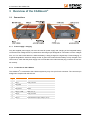
Power supply / charging
Only the supplied power supply unit must be used for power supply and charging of the integrated battery
via the extra-low voltage socket. It possesses a wide-range input designed for connection to mains voltages
from 115 V to 230 V with 50/60 Hz. While the battery is being charged, the signal lamp "Power/charging" is
lit yellow alongside the extra-low voltage socket. A green LED means that the battery is fully charged. If the
LED is not lit, check that the power supply unit is connected to the mains and the plug connector is connect ed correctly.
3.1.2
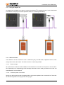
Connection to the CAN bus
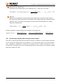
The CANtouch® is connected to the CAN bus system by way of a 9-pin D-sub connector. The connector pin
assignment complies with CiA DS-102.
Pin
Signal
Connector Pin Assignment
1
-
-
2
CAN_L
CAN_L bus line
3
CAN_GND
-
4
-
-
5
CAN_SHLD
Shield
6
CAN_V- / GND
GND / 0 V / V-
7
CAN_H
CAN_H bus line
8
-
-
2
CAN_V+
Optional external supply voltage (+24 V)
Document: 22580-HB-1-1-E-CANtouch
3