1
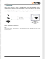
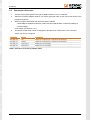
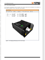
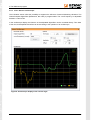
User Manual
Starter kit
Version: 1.0
Date: 2011-05-02
GEMAC - Gesellschaft für
Mikroelektronikanwendung Chemnitz mbH
Zwickauer Straße 227
09116 Chemnitz
Germany
Phone:
Fax:
E-mail:
Web:
+49 371 3377 - 0
+49 371 3377 - 272 [email protected]
www.gemac-chemnitz.de
Revision History
Revision History
Date
Revision
Changes
2011-05-02
0
First Version
© Copyright 2011 GEMAC - Gesellschaft für Mikroelektronikanwendung Chemnitz mbH
This document is subject to change without notice.
We constantly work to further develop of our products. We reserve any changes of the scope of delivery in
shape, equipment and technology for ourselves. No claims can be made from the details, illustrations and
descriptions in this document.
Any kind of duplication, reprocessing and translation of this document as well as excerpts from it require the
written permission of GEMAC mbH.
All rights according to the copyright remain explicitly reserved for GEMAC mbH.
Document: 23999-HB-1-0-E-Starter-Kit
I
Table of Contents
Table of Contents
1 Overview...................................................................................................................................................... 1
2 Start-up........................................................................................................................................................ 2
2.1 System requirements........................................................................................................................... 2
2.2 Installing the software.......................................................................................................................... 2
2.3 Connection of sensors......................................................................................................................... 3
3 The ISDControl program.............................................................................................................................. 4
3.1 General notes on operation.................................................................................................................. 4
3.1.1 Help............................................................................................................................................. 4
3.1.2 Data saving.................................................................................................................................. 4
3.2 Program structure................................................................................................................................ 4
3.2.1 Toolbar......................................................................................................................................... 4
3.2.2 View “Sensor Selection”............................................................................................................... 5
3.2.3 View “Sensor Info”....................................................................................................................... 5
3.2.4 View “Sensor Configuration”........................................................................................................ 6
3.2.5 View “Sensor 3D-View”................................................................................................................ 8
3.2.6 View “Sensor Oscilloscope”......................................................................................................... 9
4 Ordering Information.................................................................................................................................. 10
Document: 23999-HB-1-0-E-Starter-Kit
II
1 Overview
1 Overview
With the optional starter kit it is possible to adjust all inclination sensors with CAN/CANopen, current or
voltage interface. It consists of a programming adapter that is connected via USB to a PC. The connection
with the programming adapter is realized through various, also included adapter cables. The inclination
sensor is supplied with power through this. An additional power supply is not necessary.
Figure 1: Functionality of the starter kit
Note:
The inclination sensor types PR-23x2x-yy need an additional power supply (BG 03018-00) for the
programming device.
Document: 23999-HB-1-0-E-Starter-Kit
1
2 Start-up
2 Start-up
2.1 System requirements
To ensure the correct installation of the PC software, your PC or notebook should meet the following minimum requirements and possess one of the operating systems listed below.
Hardware:
Processor: 1,2 GHz or higher
at least 256 MB RAM
Graphics card with 24-bit color depth (32-bit recommended)
Resolution: 1,024x768 pixels or higher
CD/DVD ROM drive
free USB port
Supported operating systems:1:
Microsoft Windows® XP
Microsoft Windows® Server 2003
Microsoft Windows® Vista (32 Bit and 64 Bit)
Microsoft Windows® 7 (32 Bit and 64 Bit)
2.2 Installing the software
The PC software is available in German and English and is supplied on CD. The installation sets up the program ISDControl on your system and installs the USB driver required by the programming device. To this
end, perform the following steps:
1. Insert the CD into the appropriate drive of your PC.
2. The installation starts automatically.
3. Follow the instructions of the setup program.
Note:
To install the USB driver, you must possess administrator rights.
1
Microsoft and Windows® are registered trade marks of Microsoft Corporation in the USA and in other countries.
Document: 23999-HB-1-0-E-Starter-Kit
2
2 Start-up
2.3 Connection of sensors
1.
Connect the programing device through the USB interface to a PC or notebook.
2.
Select the necessary adapter cable for your sensor type (see Table 1) and connect the sensor to the
programming device.
3.
Start the program ISDControl and select the sensor interface
- CAN/CANopen (additional selection of baud rate and CAN identifier or Node-ID possible) or
- Current/Voltage
in the toolbar (see Section 3.2.1).
4.
The Device ID and serial number is displayed in the status bar of ISDControl. The connected
sensor can now be configured.
Sensor type
Interface
Adapter cable
ISXD WW P20
CAN
Adapter M12 CAN/CANopen or Adapter M8 CAN/CANopen
ISXD WW P21
CANopen
Adapter M12 CAN/CANopen or Adapter M8 CAN/CANopen
ISXD WW P24
Current output
Adapter M12 Current/Voltage
ISXD WW P25
Voltage output
Adapter M12 Current/Voltage
Table 1: Selection of necessary adapter cable
Document: 23999-HB-1-0-E-Starter-Kit
3
3 The ISDControl program
3 The ISDControl program
3.1 General notes on operation
3.1.1
Help
When designing the ISDControl program, special attention was devoted to a clear structure and a self-explaining graphical user interface. Many elements of the user interface display detailed explanations when
the mouse pointer is moved over a control element ("tool tip" or status text).
The manual is also supplied in electronic form and can be called up both via the help function and with the
F1 key.
3.1.2
Data saving
All measurement, protocol and export data set using the ISDControl program, can be stored in a document
with the file extension ".isd". The document can be opened either by double-clicking on the file in the Win dows® Explorer or by dragging the file to the program (drag & drop).
3.2 Program structure
The graphical user interface of the ISDControl program includes a toolbar and the views “Sensor Selection”,
“Sensor Info”, “Sensor Configuration”, “Sensor 3D-View” and “Sensor Oscilloscope”. All views can be freely
arranged in the program window or undocked from it.
3.2.1
Toolbar
On the toolbar, the communication parameters of the programming device can be established. These include the sensor interface (CAN/CANopen or Current/Voltage), the baud rate and the CAN identifiers or
Node-ID. The baud rate and CAN identifiers for the sensor interface Current/Voltage are fixed and can not
be adjusted.
Figure 2: Toolbar
If the sensor is connected to the programming device and has been recognized by the ISDControl program,
the complete sensor configuration (see Section 3.2.4) can be read or written. It is also possible to reset the
connected sensor to its default parameter.
Document: 23999-HB-1-0-E-Starter-Kit
4
3 The ISDControl program
3.2.2
View “Sensor Selection”
If a sensor is connected to the programming adapter and
recognized, the correct sensor type is selected automatically. All
other list entries are disabled and not editable anymore.
If no sensor is connected, you can switch freely between the
sensor types. A switch automatically displays the appropriate
configuration dialog for setting the parameters (see Section
3.2.4).
Figure 3: "Sensor Selection"
3.2.3
View “Sensor Info”
In this view, basic information (interface, serial number, firmware
version, etc.) is displayed about the connected sensor. The
sensor status is analyzed by a tooltip when the mouse pointer is
moved over the icon that appears behind it.
Figure 4: "Sensor Info"
Document: 23999-HB-1-0-E-Starter-Kit
5
3 The ISDControl program
3.2.4
View “Sensor Configuration”
Switching between the sensor types in view “Sensor Selection” (see Section 3.2.2) automatically displays
the appropriate configuration dialog for setting the parameters. The parameters set in the document are
compared with those in the sensor. Differences between the document and the sensor data are highlighted.
The transfer of the document data into the sensor can be done with the red arrow. A reading of the sensor
data in the document is possible by pressing the green arrow button. Alternatively, the document and sensor
data are updated through the tool bar (see Section 3.2.1).
Figure 5: Numerical configuration of an inclination sensor
Document: 23999-HB-1-0-E-Starter-Kit
6
3 The ISDControl program
For inclination sensors with current or voltage interface, the parametrization can be graphically. This applies
particularly to the configuration of the analog outputs for channel A and B.
Figure 6: Graphical configuration of the analog outputs of an inclination sensor
Document: 23999-HB-1-0-E-Starter-Kit
7
3 The ISDControl program
3.2.5
View “Sensor 3D-View”
By the program integrated 3D view, the position of the sensor in space can be visualized. The orientation of
the camera is variable. There is a full-screen mode available.
Figure 7: 3D imaging and display of the current angle
Document: 23999-HB-1-0-E-Starter-Kit
8
3 The ISDControl program
3.2.6
View “Sensor Oscilloscope”
The inclination sensor offers the possibility to suppress the influence of external disturbing vibrations. The
internal lowpass digital filter (Butterworth, 8th order) is programmable. The cut-off frequency is adjustable
between 0.3 and 25 Hz.
In the oscilloscope display, the influence of the adjustable digital filter can be controlled directly. Time base
of the view, and amplitude and offset can be set analog to the operation of an oscilloscope.
Figure 8: Oscilloscope display of the current angle
Document: 23999-HB-1-0-E-Starter-Kit
9
4 Ordering Information
4 Ordering Information
Article Number
Product Type Description/Distinction
PR-23999-00
ISPA1
Starter kit including programming adapter and PC software
BG-03018-00
-
ISPA1 additional power supply 24 VDC (optional)
Table 2: Ordering Information
Document: 23999-HB-1-0-E-Starter-Kit
10