1
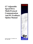
User's Manual
BM-500CL, OP22-5-1
BB-500CL, OP22-5-1
5-Megapixel Monochrome / Color
Progressive Scan Camera Link Camera
With Extended Temperature Operation
Document Version: Rev A
Document P/N: 10746
October 2010
BM-500CL, OP22-5-1 / BB-500CL, OP22-5-1
Notice
The material contained in this manual consists of information that is proprietary to JAI Ltd.,
Japan and may only be used by the purchasers of the product. JAI Ltd., Japan makes no warranty
for the use of its product and assumes no responsibility for any errors which may appear or for
damages resulting from the use of the information contained herein. JAI Ltd., Japan reserves the
right to make changes without notice.
Company and product names mentioned in this manual are trademarks or registered trademarks of
their respective owners.
Warranty
For information about the warranty, please contact your factory representative.
Certifications
CE compliance
As defined by the Directive 2004/108/EC of the European Parliament and of the Council, EMC
(Electromagnetic compatibility), JAI Ltd., Japan declares that BM-500CL/BB-500CL complies with
the following provisions applying to its standards.
EN 61000-6-3 (Generic emission standard part 1)
EN 61000-6-2 (Generic immunity standard part 1)
FCC
This equipment has been tested and found to comply with the limits for a Class B digital device,
pursuant to Part 15 of the FCC Rules. These limits are designed to provide reasonable protection
against harmful interference in a residential installation. This equipment generates, uses and can
radiate radio frequency energy and, if not installed and used in accordance with the instructions,
may cause harmful interference to radio communications. However, there is no guarantee that
interference will not occur in a particular installation. If this equipment does cause harmful
interference to radio or television reception, which can be determined by turning the equipment
off and on, the user is encouraged to try to correct the interference by one or more of the
following measures:
- Reorient or relocate the receiving antenna.
- Increase the separation between the equipment and receiver.
- Connect the equipment into an outlet on a circuit different from that to which the receiver is
connected.
- Consult the dealer or an experienced radio/TV technician for help.
Warning
Changes or modifications to this unit not expressly approved by the party
responsible for FCC compliance could void the user’s authority to operate
the equipment.
-1-
BM-500CL, OP22-5-1 / BB-500CL, OP22-5-1
-2-
BM-500CL, OP22-5-1 / BB-500CL, OP22-5-1
-3-
BM-500CL, OP22-5-1 / BB-500CL, OP22-5-1
1.
2.
3.
4.
5.
- Contents -
General ................................................................................................... 6
Camera nomenclature .................................................................................. 6
Main Features ............................................................................................ 7
Locations and Functions................................................................................ 8
Pin Assignment .......................................................................................... 9
5.1. 12-pin Multi-connector (DC-IN/Trigger) .......................................................... 9
5.2. Digital Output Connector for Camera Link....................................................... 9
5.3. Input and output circuits ..........................................................................10
5.3.1.
Iris video output ...........................................................................10
5.3.2.
Trigger input ...............................................................................10
5.3.3.
XEEN output ................................................................................10
5.3.4.
Camera Link interface ....................................................................11
6.
Functions and Operations .............................................................................12
6.1. Basic functions ......................................................................................12
6.1.1.
Digital Video Output (Bit Allocation) ...................................................12
6.1.2.
Electronic Shutter .........................................................................13
6.1.3.
Continuous operation or triggered operation .........................................13
6.1.4.
Iris video output. ..........................................................................13
6.1.5.
Rear panel indicator. .....................................................................14
6.1.6.
Auto-detect LVAL-sync / async accumulation.........................................14
6.1.7.
Starting pixel - Bayer color mosaic .....................................................14
6.1.8.
Partial Scanning ...........................................................................15
6.1.9.
Vertical binning............................................................................15
6.1.10.
Decimation readout (Draft) mode in vertical direction..............................16
6.2. Pre-process functions ..............................................................................17
6.2.1.
Bayer White Balance ......................................................................17
6.2.2.
L/R channel balance ......................................................................17
6.2.3.
Automatic output level controls ........................................................17
6.2.4.
Programmable Look-Up Table (LUT)....................................................17
6.2.5.
Blemish compensation circuit ...........................................................18
6.3. Sensor Layout and timing..........................................................................19
6.3.1.
CCD Sensor Layout ........................................................................19
6.3.2.
Horizontal timing ..........................................................................20
6.3.3.
Vertical timing .............................................................................20
6.3.4.
Partial Scan ................................................................................21
6.3.5.
Vertical Binning............................................................................22
6.3.6.
Decimation readout (Draft) mode.......................................................23
6.4. Operation Modes ....................................................................................24
6.4.1.
Continuous operation .....................................................................24
6.4.2.
Pre-Select Trigger Mode ..................................................................24
6.4.3.
Pulse Width Trigger Mode ................................................................26
6.5. Mode and function matrix. ........................................................................27
6.6. Extended temperature operation (-45 ºC to +65 ºC) ..........................................27
7.
Configuring the Camera ...............................................................................28
7.1. DIP switch SW-800 ..................................................................................28
7.2. RS-232C control .....................................................................................28
7.3. Setting functions....................................................................................29
7.3.1.
Bit allocation. BA=0, BA=1, BA=2.......................................................29
7.3.2.
Partial scan. SC=0 through 4 / Draft mode SC=5......................................29
7.3.3.
Variable (Programmable) Partial PRGP=0,1 , STL=2 to 2058, ETL = 2 to 2058...29
7.3.4.
Vertical binning............................................................................29
7.3.5.
Shutter mode. SM=0 and SM=1...........................................................29
-4-
BM-500CL, OP22-5-1 / BB-500CL, OP22-5-1
7.3.6.
Trigger input select. TI=0, TI=1. ........................................................29
7.3.7.
Trigger polarity. TP=0, TP=1.............................................................30
7.3.8.
Gain level. GA=-84 through +336........................................................30
7.3.9.
Black level. BL=255 through BL=767 ....................................................30
7.4. Save and Load Functions. .........................................................................30
7.5. BM-500CL / BB-500CL command list .............................................................31
8.
Camera Control Tool for BM-500CL/BB-500CL .....................................................35
8.1. Camera Control Tool Interface Software........................................................35
8.1.1.
Camera Control Tool Bar .................................................................35
8.2. The About Window .................................................................................35
8.3. Communication Window ...........................................................................36
8.4. Camera Control Window ...........................................................................37
8.5. Look-Up Table (LUT) ...............................................................................38
8.6. Using the Camera Control Tool ...................................................................38
9.
External Appearance and Dimensions ...............................................................39
10.
Specifications ...........................................................................................40
10.1.
Spectral response................................................................................40
10.2.
Specification table ..............................................................................41
11. Appendix.....................................................................................................43
11.1. Precautions ...........................................................................................43
11.2. Typical Sensor Characteristics .....................................................................43
11.3. Caution when mounting a lens on the camera .................................................43
11.4. Caution when mounting the camera .............................................................44
11.5. Exportation ..........................................................................................44
11.6. References...........................................................................................44
Change History ..................................................................................................46
User's Record ....................................................................................................47
-5-
BM-500CL, OP22-5-1 / BB-500CL, OP22-5-1
1. General
This manual covers the digital monochrome progressive scan camera BM-500CL, OP22-5-1
and color progressive scan camera BB-500CL, OP22-5-1
The BM-500CL, OP22-5-1 is a monochrome progressive scan CCD camera and the BB-500CL, OP225-1 is the equivalent Bayer mosaic color progressive scan CCD camera. Both have 5-megapixel
resolution, a “B Series” cube housing, a Camera Link digital interface, and have been certified for
extended temperature operation in environments ranging from -40ºC to +65ºC.
Both the monochrome version (BM-500CL, OP22-5-1) and the color version (BB-500CL, OP22-5-1)
provide a frame rate of 15 frames/second at full resolution. Using vertical binning (BM-500CL,
OP22-5-1 only), draft mode (BB-500CL, OP22-5-1 only), or partial scan, the camera can achieve
faster frame rates. The 2/3" CCD (ICX625) with square pixels offers superb image quality. The
high-speed shutter function and asynchronous random trigger mode allows the camera to capture
high quality images of fast moving objects.
The color version BB-500CL, OP22-5-1 incorporates a primary RGB Bayer mosaic filter on the CCD
to output raw Bayer images. Host-based color interpolation is required to display or save color
images. The camera features built-in white balance and dual-tap channel balancing, eliminating
the need for performing these functions on the host-PC.
The latest version of this manual can be downloaded from: www.jai.com
The latest version of the Camera Control Tool for these cameras can be downloaded from:
www.jai.com
For camera revision history, please contact your local JAI distributor.
2. Camera nomenclature
The standard camera composition consists of the camera main body and C-mount protection cap.
The camera is available in the following versions:
BM-500CL, OP22-5-1
Where B stands for "B-series” form factor, M stands for monochrome, 500 represents the
resolution "5 million pixels", CL stands for "Camera Link" interface, and OP22-5-1 refers to the
extended temperature capabilities.
BB-500CL, OP22-5-1
Where B stands for "B-series” form factor, B stands for Bayer color output, 500 represents the
resolution "5 million pixels", CL stands for "Camera Link" interface, and OP22-5-1 refers to the
extended temperature capabilities.
For simplicity, the remainder of this document will refer to the cameras without the OP22-5-1
suffix.
-6-
BM-500CL, OP22-5-1 / BB-500CL, OP22-5-1
3. Main Features
•
•
•
•
•
•
•
•
•
•
•
•
•
•
•
•
•
•
•
5-megapixel digital video camera
Certified for extended temperature operation (-40ºC to +65ºC)
2/3” progressive scan CCD Monochrome and Bayer mosaic color versions
2456 (h) x 2058 (v) resolution
3.45 µm square pixels
15 frames/second (dual-tap) with full resolution in continuous or triggered operation
Increased frame rate with vertical binning (BM-500CL only), draft mode(BB-500CL only), and
fixed or variable partial scan
Preset and auto shutter modes provided
Programmable exposure from 64µs to 66 ms in full frame scan
Edge pre-select and pulse width control modes
Exposure time from 64µs to 2 sec. using pulse width trigger mode
One-push or preset white balance for BB-500CL
Manual and automatic gain control
Look Up Table (LUT) for gamma and knee settings
Built-in blemish compensation circuit
LVAL-synchronous/-asynchronous operation (auto-detect)
Auto iris lens video output (can be selected by DIP switch)
12- or 10- or 8-bit Camera Link output
Setup by Windows NT/2000/XP/Vista/7 via serial communication
-7-
BM-500CL, OP22-5-1 / BB-500CL, OP22-5-1
4. Locations and Functions
④
⑤
POWER/ TRIG
DC IN/ TRIG
⑥
DIGITAL I / O
①
②
③
1
2
3
4
5
6
Lens mount
CCD sensor
26-pin connector
12-pin connector
LED
Mounting holes
C-mount (Note *1)
2/3 inch CCD sensor
Camera Link Interface ( Note *2)
DC+12V and trigger input
Indication for power and trigger input
M3 depth 5mm for tripod mount plate (Note *3)
*1) Note: Rear protrusion on C-mount lens must be less than 10.0mm.
*2) Note: When a Camera Link cable is connected to the camera, please do not excessively tighten
screws by using a driver. The Camera Link receptacle on the camera might be
damaged.
For security, the strength to tighten screws is less than 0.291 Newton meter (Nm).
Tightening by hand is sufficient in order to achieve this.
*3) Note: The part number for the tripod adapter plate (with 1/4"-20 thread) is MP-41 (option).
Fig. 1. Locations
-8-
BM-500CL, OP22-5-1 / BB-500CL, OP22-5-1
5. Pin Assignment
5.1. 12-pin Multi-connector (DC-IN/Trigger)
Type: HR10A-10R-12PB-01 (Hirose) male.
Use the part number HR10A-10P-12S for the cable side
Fig. 2 Hirose 12-pin connector
Pin no.
1
2
3
4
5
6
7
8
9
10
Signal
GND
+12 V DC input
GND
Iris video
GND
11
12
+12V DC input
GND
Remarks
Only for Continuous mode. TR=0
NC
NC
GND
XEEN out
Trigger in
*1)
TI=1 (or Camera Link TI=0). *2)
*3) 75 ohm termination
*1) XEEN output can be configured with complementary emitter follower circuit or open collector
by internal switch setting. The default is the complementary emitter follower circuit. See
chapter 5.3.3 for details.
*2) Factory default is trigger via Camera Link
*3) 75 ohm termination can be enabled by SW 800. See Chapter 7.1
5.2. Digital Output Connector for Camera Link
Type: 26-pin MDR connector (3M 10226-1A10PL)
Fig.3 26-Pin Camera Link Connector
Pin No
1,14
2(-),15(+)
3(-),16(+)
4(-),17(+)
5(-),18(+)
6(-),19(+)
7(+),20(-)
8(-),21(+)
9(-),22(+)
10(+),23(-)
11,24
12,25
13,26
In/Out
O
O
O
O
O
I
O
I
Name
Shield
TxOUT0
TxOUT1
TxOUT2
TxClk
TxOUT3
RxD
TxD
CC1 (Trigger)
N.C
N.C
N.C
Shield
-9-
Note
GND
Data out
Clock for CL
Data out
LVDS Serial Control
Trigger IN
GND
BM-500CL, OP22-5-1 / BB-500CL, OP22-5-1
5.3. Input and output circuits
In the following schematic diagrams the input and output circuits for video and timing signals are
shown.
5.3.1. Iris video output
This signal can be used for lens iris control in continuous mode.
The signal for iris video output is taken from the video signal after
the gain control. The signal is 0.7 Vpp (without sync) from 75 Ω
without termination.
+5V
0.1μ
2K2
IRIS Video Out
1K
1μ
DAC
Fig. 4. Iris video
5.3.2. Trigger input
An external trigger input can be applied to pin 10 of the
12-pin Hirose connector (when the command TI=1 has
been set). The input is AC coupled. To allow long pulses
the input circuit is designed as a flip-flop circuit. The
leading and trailing edges of the trigger pulse activate
the circuit.
The trigger polarity can be changed by TP=1.
Trigger input level 4 V ± 2 V.
Trigger can also be applied through the Camera Link
connector, when the command TI=0 has been sent.
+5V
Trig input
pin #10
15k
100n
75Ω
1k
68k
SW302.1
GND
1n
Fig. 5. Trigger input.
5.3.3. XEEN output
XEEN is on pin 9 of the 12-pin Hirose connector.
The output uses either a complementary emitter
follower circuit or open-collector. The output of the
complementary emitter follower circuit is ≥ 3 V. (No
termination)
When the open corrector output is used, the maximum
current is 120mA. However, if the current is more than
50mA, use thicker cable for connecting pins #8 and #9.
If a thinner cable is used, it might cause a malfunction
due to the resistance of the cable.
The output can be selected by switch SW800 located
inside the camera (rear board).
Fig. 6. XEEN output
EEN is also found in Camera Link.
- 10 -
TTL
100k
1k
GND
BM-500CL, OP22-5-1 / BB-500CL, OP22-5-1
5.3.4. Camera Link interface
The digital video is available via Camera Link, with 8-, 10- or 12-bit pixel depth, using the CL Base
configuration. The digital output signals follow the Camera Link standard using Channel Link chip
sets.
The data bits from the digital video, FVAL, LVAL, DVAL and EEN are multiplexed into the twisted
pairs, which are a part of Camera Link. Trigger signals and the serial camera control are fed
directly through its own pairs.
The 26-pin MDR Camera Link connector pin assignment follows the Camera Link Base
configuration.
For a detailed description of the Camera Link standard, please refer to the Camera Link standard
specifications found at the AIA web site, www.machinevisiononline.org.
- 11 -
BM-500CL, OP22-5-1 / BB-500CL, OP22-5-1
6. Functions and Operations
6.1. Basic functions
The BM-500CL/BB-500CL cameras are progressive scan cameras with 5-megapixel monochrome or
Bayer mosaic color CCDs. The interface to the host PC is via digital Camera Link. Both models can
output video as 8-, 10- or 12-bit Camera Link data. The BB-500CL outputs raw Bayer video,
requiring host-based color interpolation. The cameras also feature several pre-processing
functions (see chapter 6.2)
An analog iris-video signal can be used for controlling the iris of an auto-iris lens when operating
in continuous mode.
The cameras have both variable partial scan (user programmable) or fixed 2/3, 1/2, 1/4 and 1/8
image height scanning. Vertical binning (BM-500CL only) and decimation readout (BB-500CL) are
also available for faster frame rates.
There are 2 trigger modes in addition to continuous operation. The Pre-Select and Pulse Width
trigger modes are available with a unique automatic LVAL sync or async selection function.
The functions are described in detail in the following sections.
6.1.1. Digital Video Output (Bit Allocation)
The 10-bit digital output is set at 890 LSB as 100% video level when CCD output is 200mV.
The white clip level is set at 1023 LSB when CCD output is 230mV.
CCD out
Analogue level
Black
200mV
230mV↑
Setup 3.6%, 25mV
700mV
800mV
8 bits
8 LSB
222 LSB
255 LSB
Digital Out
10 bits
32 LSB
890 LSB
1023 LSB
Fig.7. Digital Output Bit Allocation (in case of 10 bits )
- 12 -
12 bits
128 LSB
3560 LSB
4095 LSB
BM-500CL, OP22-5-1 / BB-500CL, OP22-5-1
6.1.2. Electronic Shutter
The BM/BB-500CL allows selecting shutter speed in two ways; preset shutter (10 fixed steps) and
programmable exposure (in 2072 line-period LVAL increments).
Preset Shutter (SH)
The following shutter speeds can be selected by command SH=0 through SH=10.
OFF (1/15), 1/30, 1/60, 1/100, 1/250, 1/500, 1/1000, 1/2000, 1/4000, 1/8000, 1/10000 seconds
Programmable Exposure (PE)
The exposure time can be programmed in 32.067µs (LVAL period) increments. The range is from 2
LVAL to 2072 LVAL.
Minimum exposure time 2L
32.067µs x 2(L) = 64.13 µs
Maximum exposure time 2072 L
32.067µs x 2072 (L) ≈ 66.44 ms
In binning mode:
Minimum Exposure time 2L
42.067 µs x 2(L) = 84.13 µs
Maximum exposure time 1029 L
42.067 µs x 1029 (L) ≈ 43.71 ms
In draft mode
Minimum exposure time 2L
102.066 µs x 2(L) = 204.132 µs
Maximum exposure time 261 L
102.066 µs x 261 (L) ≈ 26.64 ms
Auto Shutter (ASC)
The setting command is ASC. This command activates the auto shutter function. This function
controls the shutter speed according to light changes and keeps the specified video level. Auto
shutter controls from OFF (1/15) to 1/250 seconds.
6.1.3. Continuous operation or triggered operation
The camera can operate in continuous operation for applications not requiring an asynchronous
external trigger. This mode permits the use of a lens with a video-controlled iris. The camera will
operate at its maximum frame rate, 15.05 frames/seconds in this mode.
For applications that require an external trigger, the camera can accept an external trigger input
on pin 10 of the 12-pin Hirose connector or via the Camera Link interface. The command "TI" is
used to switch between inputs.
The camera can operate at up to 15 frames/second in triggered operation.
6.1.4. Iris video output.
The iris video output on pin 4 of the 12-pin Hirose
connector outputs 700 mV when the video out in Camera
Link is at the 100% level. The iris video signal is taken after
the gain circuit. It is without sync.
The iris video signal can be used to drive an auto iris lens in
continuous mode.
Fig. 8. Iris video output.
- 13 -
BM-500CL, OP22-5-1 / BB-500CL, OP22-5-1
6.1.5. Rear panel indicator.
The rear panel mounted LED provides the following information:
Amber:
Power connected - initiating
Steady green: Camera is operating in Continuous mode
Flashing green: The camera is receiving external trigger
POWER/ TRIG
DC IN / TRIG
DIGITAL I / O
DIGITA
6.1.6. Auto-detect LVAL-sync / async accumulation
This function replaces the manual setting found in older JAI cameras. Whether accumulation is
synchronous or asynchronous in relationship to LVAL depends on the timing of the trigger input.
When a trigger is received while FVAL is high (during readout), the camera works in LVALsynchronous mode, preventing reset feed-through in the video signal. There is a maximum jitter
of one LVAL period from issuing a trigger to the start of accumulation. When a trigger is received
during FVAL low, the camera works in LVAL-asynchronous mode (no delay mode).
This applies to both Pre-Select (PS) trigger mode and Pulse Width (PW) trigger mode.
External Trigger
(1)
(2)
+/- 1 LVAL
(3)
FVAL
(1) In this period camera executes trigger at next LVAL (prevents feed-through noise)
(2) Avoid trigger at FVAL transition (+/- LVAL period), as the function may randomly
switch between “ next LVAL ” and “ immediate ”.
(3) In this period, camera executes trigger immediately ( no delay).
Fig.9 Auto-detect LVAL sync/async accumulation
6.1.7. Starting pixel - Bayer color mosaic
The BB-500CL is a color camera based on a CCD
sensor with a Bayer color mosaic.
The color image reconstruction is done in the host
PC.
The color sequence in the video signal is the same
for any scanning modes except programmable partial
scan.
The right-hand drawing shows the color sequence at
the image start.
The starting line number is shown from LVAL.
The first active pixel starts from LVAL, when DVAL
rises.
Even lines starts with GBG.
Odd lines starts with RGR
See also chapter 6.1.8 Partial Scan
Fig. 10. Bayer color mosaic
- 14 -
BM-500CL, OP22-5-1 / BB-500CL, OP22-5-1
6.1.8. Partial Scanning
The partial scanning function uses the middle of the image vertically to achieve a faster frame
rate. This is effective for capturing and inspecting images which do not require the full height.
The BM-500CL and BB-500CL have 4 fixed partial scan modes including 2/3, 1/2, 1/4 and 1/8.
Variable Partial Scan
Additionally, the BM-500CL/BB-500CL has a variable partial scan function. The start line and end
line of the image can be set by the command STL and ETL.
The command PRGP = 1 is used to activate this function.
Line setting
Command
Parameter
Start line
STL =
2 to 2058
End line
ETL =
2 to 2058
The effective read out lines can be calculated from the following formula.
The End line – the Start line + 1
Frame rate calculation
Frame rate ( fps ) = 1/ ( Total LVAL number of 1 frame x 32 µs )
Total LVAL number of 1 frame
= FVAL LOW period + Upper Fast dump period + Normal read out period + Lower Fast dump period
FVAL LOW = 4 ( lines)
Upper Fast Dump period =
+ 2 ( lines )
Note) The first decimal place is rounded up.
Normal read out = The End line – the Start line + 1 ( lines )
+ 7 ( lines )
Lower Fast Dump period =
Note) The first decimal place is rounded up.
6.1.9. Vertical binning
This function is only available on the BM-500CL camera. Binning mode (Command VB) is a function
where the signal charge from 2 adjacent (vertical) pixels are added together and read out as one
pixel. Binning results in half vertical resolution and higher frame rate. By adding 2 pixels together,
the sensitivity is doubled. The charge accumulated in 2 adjacent lines is added together in the
- 15 -
BM-500CL, OP22-5-1 / BB-500CL, OP22-5-1
horizontal CCD register. This is done by providing two pulses to the vertical CCD register for each
line read out. Vertical binning can not be used together with partial scan.
Fig. 11. Vertical Binning
6.1.10. Decimation readout (Draft) mode in vertical direction
BB-500CL has a decimation readout (draft) mode. 4 lines of every 16 lines, 2 GB lines and 2 RG
lines, are combined before being read out. When using this mode the field of view is maintained
but the height of the image is reduced to 1/8 which is 261 lines. The frame rate is 37.54 frames
per second.
Fig.12. Draft mode
- 16 -
BM-500CL, OP22-5-1 / BB-500CL, OP22-5-1
6.2. Pre-process functions
BM-500CL/BB-500CL has several pre-processing functions. The output from the camera is
selectable to 8-, 10- or 12-bits but video is digitized to 14-bit internally. The pre-processing
functions make use of the 14-bit video. Featured functions are: white balance (BB-500CL only),
R/L channel balance, blemish compensation, gain control and LUT (Look Up Table) for gamma and
knee correction.
6.2.1. Bayer White Balance
Normally, the raw Bayer color signals are sent to the host as they are. In the host, the signals are
interpolated to generate an RGB image and perform white balancing. In order to offload the host,
the BB-500CL can adjust Gr, R , Gb and B levels individually to get the white balance for the Bayer
output signal.
White Balance Type
Preset ( 3200K , 4600K , 5600K )
One–Push White Balance
Manual
White Balance Areas
Setting
AWBM=1 ( 3200), = 2 (4600), = 3 (5600 )
AWBM=0 ( One-push),
AWB = 1 for activate ( 2600K to 6500K)
Set by pixel gain ( R1/R2, GR1/GR2, B1/B2, GB1/GB2)
Select 6 divided area for both L and R channels
Note: Bayer white balance should be adjusted in continuous mode.
6.2.2. L/R channel balance
The BM-500CL/BB-500CL has a dual-tap readout architecture with a Left (L) and Right (R) channel.
In order to achieve the same gain and black level for both channels, the BM-500CL/BB-500CL has a
built-in R/L channel balance function. The function is activated by a “one-push” software
command.
Channel Balance Type
One-Push Gain (Auto White Level Adjust, AWA)
One-Push Auto Black Level Adjust (ABA)
Setting
AWA=1 for activation
ABA=1 for activation
Note: 1. Channel balance adjustment should be done in continuous mode.
2. One-push channel balance should be done in the following order: ABA and then AWA.
6.2.3. Automatic output level controls
These functions help to maintain a constant output level in accordance with ambient brightness
changes. The two functions are AGC (Auto Gain Control) and ASC (Auto Shutter Control).
AGC and ASC cannot be used at the same time.
Functions
Gain Mode (AGC)
Auto Shutter Control (ASC)
Setting
AGC=0 ( Manual ) AGC = 1 ( AGC ON )
ASC= 0 ( OFF )
ASC = 1 ( ON )
Note: Only available in continuous mode.
6.2.4. Programmable Look-Up Table (LUT)
BM-500CL/BB-500CL has a programmable look-up table (LUT) that lets the user adjust the transfer
function of the video output. Selectable settings include multiple-point LUT and Gamma 0.45.
- 17 -
BM-500CL, OP22-5-1 / BB-500CL, OP22-5-1
The look up table has 256 setting points by which the full range of input signal is divided. On each
of the points, the gain can be set to get the required transfer function. In the case of the BB500CL, Gr, R, Gb and B signals all have the same characteristics. Gamma 0.45 or programmable
LUT can be selected by software control. If the LUT is not configured, Gamma is set at 1.0 (OFF).
6.2.5. Blemish compensation circuit
BM-500CL/BB-500CL has a blemish compensation circuit. This function compensates for blemishes
on the CCD sensor (typically pixels with extremely high response or extremely low response). This
applies to both monochrome and color versions. Pixels that fulfill the blemish criteria can be
compensated by pixels in both adjacent columns. The number of compensated pixels is up to 8 on
both L and R channels. In case of BB-500CL, the defective pixels can be compensated by using the
same Bayer color pixels in both adjacent columns. The compensation circuit can be enabled or
disabled by software control. The factory default is OFF.
- 18 -
BM-500CL, OP22-5-1 / BB-500CL, OP22-5-1
6.3. Sensor Layout and timing
6.3.1. CCD Sensor Layout
The CCD sensor layout, with respect to pixels and lines used in the timing and video full frame
readout, is shown below. For Bayer color sequence, refer to chapter 6.1.7.
2
OB
Active Pixel Output
2058
2456(H) x 2058(V)
(1,1)
8
1 24 16
L Channel 1228
R channel 1228
Dummy OB
16 24 1
OB Dummy
Fig. 13. CCD sensor layout
- 19 -
OB
BM-500CL, OP22-5-1 / BB-500CL, OP22-5-1
6.3.2. Horizontal timing
The LVAL period is shown for continuous mode.
H-Timing FULL FRAME READ OUT / PATIAL READ OUT
1LVAL 1924ck = 32us
1ck=
16. 66ns
LVAL
DATA OUT
OB
Valid data
OB
1228ck
40ck
1268ck
656ck
1228ck
696ck
DVAL
Fig. 14. Horizontal timing
6.3.3. Vertical timing
The FVAL period for continuous mode full scan is shown.
FULL FRAME READ OUT FRAME RATE 2072L 15.05fps
LVAL
2072L
FVAL
123
DAVL
DATA
4L
8L
OB
2056 2057 2058
2058L
Valid data
2L
OB
OB
2L
CCD Exposure
EEN
XEEN
Fig. 15. Vertical timing for full scan
- 20 -
BM-500CL, OP22-5-1 / BB-500CL, OP22-5-1
6.3.4. Partial Scan
Partial scan allows higher frame rates by reading out a smaller center portion of the image. This is
particularly useful when inspecting objects that do not fill the whole height of the image.
Fast-dump period
Normal scan period
Fast-dump period
Full scan
Partial scan
Vertical Timing
The diagram and table below provide vertical timing information for the fixed partial scan settings
of 2/3, 1/2, 1/4, and 1/8.
PATIAL FRAME READ OUT
LVAL
FVAL
DAVL
4L
DATA
Valid data
CCD Exposure
2L
EEN
XEEN
A
B
C
Values for vertical timing in partial scan continuous mode.
C
Total line frame rate
B (L)
FVAL Low
A
AREA
(L)
(L)
(L)
(L)
(L)
Start line
End line
1030
1/2
4
176
93 L
1303 L
23.93
515
1544
514
1/4
4
262
136 L
918 L
34.04
773
1286
258
1/8
4
304
158 L
724 L
43.07
901
1158
1374
2/3
4
118
65 L
1561 L
19.97
343
1716
Remark! The color sequence for BB-500CL differs in partial scan. Refer to chapter 6.1.7.
Fig. 16. Vertical timing for partial scanning
- 21 -
BM-500CL, OP22-5-1 / BB-500CL, OP22-5-1
Horizontal Timing
The horizontal timing is the same as for full scanning.
H-Timing FULL FRAME READOUT / PARTIAL READOUT
Fig. 17. Horizontal timing for partial scanning
6.3.5. Vertical Binning
Vertical binning combines charge from two adjacent lines, reducing the vertical resolution to half
and at the same time increasing frame rate and sensitivity. By activating this function, the frame
rate is increased to 22.88 fps. This function is available only for BM-500CL. Vertical binning can
not be used together with partial scanning.
Horizontal Timing
H-Timing V binning
Fig. 18. Horizontal timing for vertical binning
- 22 -
BM-500CL, OP22-5-1 / BB-500CL, OP22-5-1
Vertical Timing
V binning FRAME RATE 1039L (1029L active) @ 22.88 fps
Fig. 19. Vertical timing for vertical binning
6.3.6. Decimation readout (Draft) mode
The draft mode reads out and combines 2 line pairs out of every 16 lines. The frame rate is 37.54
frames per second.
Draft FRAME RATE 261L 37.54fps
LVAL
FVAL
1L
1+2 8+12
2040+2044 2049+2053
DAVL
3L
DATA
257L
Valid data
CCD Exposure
2L
EEN
XEEN
Fig.20. Vertical Timing for Draft Mode
- 23 -
BM-500CL, OP22-5-1 / BB-500CL, OP22-5-1
6.4. Operation Modes
This camera can operate in 3 primary modes.
1.
2.
3.
TR=0
TR=1
TR=2
Continuous Mode.
Pre-Select Mode.
Pulse Width Mode.
Pre-selected exposure.
Pre-selected exposure.
Pulse width controlled exposure.
6.4.1. Continuous operation
For applications not requiring asynchronous external triggering, this mode is used.
For timing details, refer to fig. 14 through fig. 20.
To use this mode:
Set function:
Trigger mode to “Continuous”.
Scanning
Programmable Partial
Shutter mode pre-set or programmable
Shutter speed or
Programmable exposure
Auto shutter
Other functions and settings
TR=0
SC=0 through 5
PRGP=1
SM=0 or 1
SH=0 to 10
PE=2 to 2072
ASC=0 or 1
6.4.2. Pre-Select Trigger Mode
An external trigger pulse initiates the capture, and the exposure time (accumulation time) is
defined by the SH or PE commands.
The resulting video signal will start to be read out after the selected shutter time.
For timing details, refer to fig. 14 through fig. 20 and fig. 21 & 22.
To use this mode:
Set function:
Input:
Trigger mode to “Edge pre-select”.
Scanning
Programmable Partial
Shutter mode to pre-set or programmable
Shutter speed or
Programmable exposure
Auto shutter
Other functions and settings
Ext. trigger. Camera Link or 12-pin Hirose
TR=1
SC=0 to 5
PRGP=0 or 1
SM=0 or 1
SH=0 to 10
PE=2 to 2072
ASC=0 or 1
TI=0, TI=1
Important notes on using this mode
1. The minimum trigger duration >2 LVAL.
2. Depending on the timing of the leading edge of the trigger pulse in relationship to FVAL,
accumulation will be synchronous or asynchronous in relationship to LVAL. See section
6.1.6 for details.
3. The minimum interval of the trigger is as follows (in case of LVAL sync). In LVAL async
mode, the exposure period should be added.
Full
2/3
1/2
1/4
1/8
VBinning
2077
1566
1308
921
729
1043
- 24 -
BM-500CL, OP22-5-1 / BB-500CL, OP22-5-1
LVAL sync timing
EPS LVAL SYNC
TRIG
2 L(min)
LVAL
CCD Exposure
1L(max)
EEN
Exposure period
XEEN
FVAL
Trigger input during FVAL HIGH
2L
sets LVAL SYNC mode
Fig. 21. Pre-Select trigger mode. LVAL synchronous.
LVAL async timing
EPS LVAL ASYNC
8µ s± 1µ s
TRIG
2L(min)
CCD Exposure
EEN
Exposure period
XEEN
FVAL
Trigger input during FVAL HIGH
sets LVAL ASYNC node
2L~3L
Fig.22. Pre-Select trigger mode. LVAL asynchronous.
- 25 -
BM-500CL, OP22-5-1 / BB-500CL, OP22-5-1
6.4.3. Pulse Width Trigger Mode
In this mode the accumulation time is equal the trigger pulse width. Here it is possible to have a
long time exposure. The maximum recommended time is <60 frames.
For timing details, refer to fig. 14 through fig. 20 and fig. 23 & 24.
To use this mode:
Set function:
Trigger mode to “Pulse width control”.
Partial scan
Programmable Partial
Other functions and settings
Ext. trigger. Camera Link or 12-pin Hirose
Input:
TR=2
SC=0 to 5
PRGP-0 or 1
TI=0, TI=1
Important notes on using this mode
1. The minimum trigger duration >1 LVAL (LVAL async), >2 LVAL (LVAL sync)
2. Depending on the timing of the leading edge of the trigger pulse in relationship to FVAL,
accumulation will be synchronous or asynchronous in relationship to LVAL. See section
6.1.6 for details.
3. The minimum interval of the trigger is as follows (in case of LVAL sync). In LVAL async
mode, the exposure period should be added.
Full
2/3
1/2
1/4
1/8
V-binning
2077
1566
1308
921
729
1043
LVAL sync timing
PWC LVAL SYNC
TRIG
2 L(min)
LVAL
1L
1L( max)
CCD Exposure
EEN
XEEN
Exposure Period
FVAL
Trigger input during FVAL HIGH
2L~3L
sets LVAL SYNC mode
Fig. 23. Pulse width trigger mode. LVAL synchronous.
- 26 -
BM-500CL, OP22-5-1 / BB-500CL, OP22-5-1
LVAL async timing
PWC LVAL ASYNC
8 µ s± 1µ s
TRIG
1L(min)
1L - 10us
CCD Exposure
EEN
Exposure period
XEEN
FVAL
Trigger input during FVAL LOW
2L~3L
sets LVAL ASYNC
Fig.24. Pulse Width trigger mode. LVAL asynchronous.
6.5. Mode and function matrix.
The following table shows which functions will work in the different modes for the BM-500CL / BB500CL.
Func
Trigger mode
Shutter
Pre-set
Programmable
Auto
Shutter
Partial
Accumulation
Iris video
LVAL sync / async
output
Cont.
TR=0
○
○
○
○
-
○
EPS
TR=1
○
○
×
○
Auto
-
PWC
TR=2
―
―
×-
○
Auto
-
Fig. 24. Mode and function matrix.
6.6. Extended temperature operation (-45 ºC to +65 ºC)
The OP22-5-1 model suffix indicates that the BM-500CL/BB-500CL cameras are individually tested,
validated and temperature cycled to certify their operating ability throughout an extended
temperature range which is greater than the operating range of typical COTS (commercial off-theshelf) cameras. Although units are guaranteed to operate throughout the temperature range,
operating the camera beyond the standard range of -5 ºC to +45 ºC may result in some reduced
performance characteristics, such as higher noise, reduced SNR, etc. Specifications shown in the
camera data sheet and in the table at the back of this document are for when the camera is
operating within normal temperature conditions and may be subject to variations when operating
in extreme temperatures.
- 27 -
BM-500CL, OP22-5-1 / BB-500CL, OP22-5-1
7. Configuring the Camera
7.1. DIP switch SW-800
This switch has following functions.
1. Select the circuit for WEEN output at pin 9 of the Hirose connector.
2. Enable/Disable 75 ohm termination for the trigger input, pin 10 on the Hirose connector.
The switch can be accessed by removing the top cover. The defaults are shown in the diagram
below.
7.2. RS-232C control
All configuring of the BM-500CL/BB-500CL is done via the serial communication in the Camera Link
connector. The camera can be set up from a PC running terminal emulator software, or using JAI's
camera control software. Below is the description of the ASCII based short command protocol.
Communication setting.
Baud Rate
Data Length
Start Bit
Stop Bit
Parity
Xon/Xoff Control
9600 bps
8 bit
1 bit
1 bit
None
None
RS 232C cable
TXD
CAMERA RXD
GND
1 CD
4 DTR
6 DSR
2 RXD
3 TXD
5 GND
7 RTS
8 CTS
9 CI
9 pin
D-con
PC COM
PORT
Protocol.
Transmit setting to camera:
NN=[Parameter]<CR><LF> (NN is any kind of command. Capital or small letters.)
The camera answers:
COMPLETE<CR><LF>
To have all communication visible on the emulator screen, start with:
EB=1<CR><LF>
The camera answers:
COMPLETE<CR><LF>
Transmit request command to camera:
NN?<CR><LF> (NN is any kind of command.)
The camera answers:
NN=[Parameter]<CR><LF>
- 28 -
BM-500CL, OP22-5-1 / BB-500CL, OP22-5-1
Transmit the following to get the camera’s actual settings:
ST?<CR><LF>
The camera answers:
A complete list of the current settings
Transmit the following to get a command list:
HP?<CR><LF>
The camera answers:
A list with all commands and possible settings
Invalid parameters sent to camera: (99 is an invalid parameter)
SH=99<CR><LF>
The camera answers:
02 Bad Parameters!!<CR><LF>
To see firmware number.
VN?<CR><LF>
To see camera ID. It shows the manufacturing lot number.
ID?<CR><LF>
7.3. Setting functions
7.3.1. Bit allocation. BA=0, BA=1, BA=2
This command sets the output for 8-bit , 10-bit or 12-bit.
7.3.2. Partial scan. SC=0 through 4 / Draft mode SC=5
The CCD scanning format can be selected between full or partial scanning. With partial scanning
only the vertical central part of the CCD sensor is read out with a higher frame rate. The partial
scan is done by a fast dump read out of the lines in the vertical CCD register down to the top of
the partial image. This central part of the image is read out with normal speed. The lines below
the partial image are read out and dumped with a high speed. Refer to the Chapter 6.2.4.
When SC is set at “5”, the Draft mode can be activated. Refer to the Chapter 6.1.9.
7.3.3. Variable (Programmable) Partial PRGP=0,1 , STL=2 to 2058, ETL = 2 to 2058
The variable partial scan can set the start line and the end line of the scan to capture the
necessary portion of the image.
7.3.4. Vertical binning
This function is only for BM-500CL camera. The BM-500CL has only vertical binning mode. With V
binning the pixel charge from 2 adjacent lines are added together in the horizontal CCD register.
It is done by double pulses to the vertical CCD register. V Binning can not be used together with
partial scanning.
7.3.5. Shutter mode. SM=0 and SM=1
With SM=0 this function selects the shutter from the 9 fixed steps (SH=0 through SH=9SH).
With SM=1 from programmable in 2071 steps (PE=2 through PE=2072).
7.3.6. Trigger input select. TI=0, TI=1.
This function selects the trigger input to be through Camera Link (TI=0), or as TTL through the 12pin Hirose connector (TI=1).
- 29 -
BM-500CL, OP22-5-1 / BB-500CL, OP22-5-1
7.3.7. Trigger polarity. TP=0, TP=1.
The active trigger polarity is normally low (TP=0). It can be inverted to active high (TP=1).
7.3.8. Gain level. GA=-84 through +336.
GA=0 is 0dB gain, which is normal working point. The range is from -3 dB to +12 dB.
7.3.9. Black level. BL=255 through BL=767
Black level (or set-up level) will set the video level for black. Factory setting is 128 LSB for 12-bit,
32 LSB for 10-bit or 8 LSB for 8-bit.
7.4. Save and Load Functions.
The following commands are for store and load camera settings in the camera EEPROM.
Load settings. LD.
This command will load previously stored settings to the camera. 3 user settings can be stored in
the camera’s EEPROM. 1 factory setting is also stored in the camera. The settings stored in the
last used user area are used as default settings at power up.
Save Settings. SA.
This will store the actual camera settings to 1 of the 3 user areas in the camera’s EEPROM.
EEPROM Area. EA.
If received, the camera will return the last used user area number.
- 30 -
BM-500CL, OP22-5-1 / BB-500CL, OP22-5-1
7.5. BM-500CL / BB-500CL command list
Command Name
Format
Parameter
Remarks
A - General settings and utility commands.
1
Camera Status
Request
ST?<CR><LF>
Actual setting
2
Online Help
Request
HP?<CR><LF>
Command list
3 digits
(e.g.) 100 =
Version 1.00
3 Firmware Version VN?<CR><LF>
4
Camera ID
Request
ID?<CR><LF>
max 12 characters
5
Model Name
Request
MD?<CR><LF>
max 12 characters
6
User ID
UD=[Param.]<CR><LF>
UD?<CR><LF>
User can save and
load free text.(12
or less characters)
7
Error Code
ERROR=[Param.]<CR><LF>
ERRER?<CR><LF>
O=Not completed yet
1=Succeeded
2=Error 1, G ch image too
bright
3=Error 2, G ch image too
dark
4=Error 3, Time out error
SM=[Param.]<CR><LF>
SM?<CR><LF>
0=Preset Shutter
1=Programmable exposure
Available when
SM=0.
Available when
SM=1.
One of values is
back from camera
B – Shutter
1
Shutter Mode
2
Preset Shutter
SH=[Param.]<CR><LF>
SH?<CR><LF>
0=Off, 1=1/60, 2=1/100,
3=1/250, 4=1/500,
5=1/1000, 6=1/2000,
7=1/4000, 8=1/8000,
9=1/10000
3
Programmable
Exposure
PE=[Param.]<CR><LF>
PE?<CR><LF>
2 to 2072
C - Trigger mode
1
Trigger Mode
TR=[Param.]<CR><LF>
TR?<CR><LF>
0=Normal (Continuous)
1=EPS(Pre select)
2=PWC(Pulse width)
2
Trigger Polarity
TP=[Param.]<CR><LF>
TP?<CR><LF>
0=Active Low
1=Active High
3
Trigger Input
TI=[Param.]<CR><LF>
TI? <CR><LF>
0=Camera Link
1=Hirose 12pin
- 31 -
BM-500CL, OP22-5-1 / BB-500CL, OP22-5-1
Command Name
Format
Parameter
Remarks
D -Image Format
1
Bit Allocation
BA=[Param.]<CR><LF>
BA?<CR><LF>
0=8bit, 1=10bit, 2=12bit
2
Scan Format
SC=[Param.]<CR><LF>
SC? <CR><LF>
0=Full Frame
1=2/3 Partial
2=1/2 Partial
3=1/4 Partial
4=1/8 Partial
5=Decimation (Draft)
3
V-binning
VB=[Param.]<CR><LF>
VB?<CR><LF>
0=OFF
1=ON
Only for BM-500CL
4
Variable partial
scan
PRGP=[Param.]<CR><LF>
PRGP?<CR><LF>
0=OFF
1=ON
For Programmable
partial
5
Start line
STL=[Param.]<CR><LF>
STL?<CR><LF>
2 to 2058
For Programmable
partial
6
End line
ETL=[Param.]<CR><LF>
ETL?<CR><LF>
2 to 2058
For Programmable
partial
E - Gain, Black and signal settings
GA=[Param.]<CR><LF>
GA?<CR><LF>
-84 to 336
GJUT2=[Param.]<CR><LF>
GJUT2?<CR><LF>
-84 to 84
Gain Mode
AGC=[Param.]<CR><LF>
AGC?<CR><LF>
0= Manual Gain Control
1=Auto Gain Control
4
AGC Reference
AGCF=[Param.]<CR><LF>
AGCF?<CR><LF>
0 to 8192
5
Black Level
BL=[Param.]<CR><LF>
BL?<CR><LF>
255 to 767
6
User Black
setup 1
BLS=[Param.]<CR><LF>
BLS?<CR><LF>
-511 to 511
For AFE1
7
User Black
setup 2
BLS2=[Param.]<CR><LF>
BLS2?<CR><LF>
-511 to 511
For AFE2
8
Black fine2
BLF2=[Param.]<CR><LF>
BLF2?<CR><LF>
-255 to 256
For AFE2
AWBM=[Param.]<CR><LF>
AWBM?<CR><LF>
0=One push 1=3200K
2=4600K
3=5600K
1
Gain Level
2
Gain Adjust 2
3
F – AWB and others
1
AWB mode
2
One Push AWB
AWB=[Param.]<CR><LF>
1=Run
3
One Push AWA
AWA=[Param.]<CR><LF>
1=Run
Ch-to-ch gain
4
One Push ABA
ABA=[Param.]<CR><LF>
1=Run
Ch-to-ch black
- 32 -
BM-500CL, OP22-5-1 / BB-500CL, OP22-5-1
Command Name
Format
Parameter
Remarks
level
5
Auto Shutter
Control
ASC=[Param.]<CR><LF>
ASC?<CR><LF>
0=OFF; 1=ON
6
Channel 1 area
CHA1=[Param.]<CR><LF>
CHA1?<CR><LF>
1=Low right, 2=Low left
4=Middle Right, 8=Mid. left
16=High Right,32=High Left
7
Channel 2 area
CHA2=[Param.]<CR><LF>
CHA2?<CR><LF>
1=Low right, 2=Low left
4=Middle Right, 8=Mid. left
16=High Right,32=High Left
8
LUT Control
LUTC=[Param.]<CR><LF>
LUTC?<CR><LF>
0=OFF; 1=ON
9
LUT Data
Communication
LUT1=[Param.]<CR><LF>
LUT1?<CR><LF>
0.45, LUT (256)
10
LUT Data
Communication
LUT2=[Param.]<CR><LF>
LUT2?<CR><LF>
Transmit LUT2=1 after 256
data transmission
11
Send Gamma
Coefficient
Gamma=[Param.]<CR><LF>
4096=Linear ,1843=0.45
Serial comm..
256 data
12
Test Pattern
TPN=[Param.]<CR><LF>
TPN?<CR><LF>
0=OFF, 1=white noise
2=Horizontal grey
3=Vertical grey
4=Moving grey
5=Color bar 1
6=Color bar 2
7=Moving Color bar
13
Blemish
Compensation
BLM=[Param.]<CR><LF>
BLM?<CR><LF>
0=OFF, 1=ON
14
Pixel Offset
switch
POS=[Param.]<CR><LF>
POS?<CR><LF>
0=OFF, 1=ON
15 Pixel Gain switch
PGS=[Param.]<CR><LF>
PGS?<CR><LF>
0=OFF, 1=ON
16
Pixel Gain R1
PGR=[Param.]<CR><LF>
PGR?<CR><LF>
0 to 16384
For AFE1
17
Pixel Gain GR1
PGGR=[Param.]<CR><LF>
PGGR?<CR><LF>
0 to 16384
For AFE1
18
Pixel Gain B1
PGB=[Param.]<CR><LF>
PGB?<CR><LF>
0 to 16384
For AFE1
19
Pixel Gain GB1
PGGB=[Param.]<CR><LF>
PGGB?<CR><LF>
0 to 16384
For AFE1
20
Pixel Gain R2
PGR2=[Param.]<CR><LF>
PGR2?<CR><LF>
0 to 16384
For AFE2
21
Pixel Gain GR2
PGGR2=[Param.]<CR><LF>
PGGR2?<CR><LF>
0 to 16384
For AFE2
- 33 -
BM-500CL, OP22-5-1 / BB-500CL, OP22-5-1
Command Name
22
Pixel Gain B1
23
Pixel Gain GB1
Format
Parameter
Remarks
PGB2=[Param.]<CR><LF>
PGB2?<CR><LF>
0 to 16384
For AFE2
PGGB2=[Param.]<CR><LF>
PGGB2?<CR><LF>
0 to 16384
For AFE2
G - Saving and loading data in EEPROM
1
2
3
Load Settings
(from Camera
EEPROM)
Save Settings
(to Camera
EEPROM)
0=Factory area
1=User 1 area
2=User 2 area
3=User 3 area
LD=[Param.]<CR><LF>
1=User 1 area
2=User 2 area
3=User 3 area
Note : parameter 0 is not
allowed
SA=[Param.]<CR><LF>
0=Factory area
1=User 1 area
2=User 2 area
3=User 3 area
EEPROM Current
EA?<CR><LF>
Area No Request.
NOTE: Do not try to use commands not shown in this list.
- 34 -
Latest used DATA
AREA becomes
default at next
power up.
The camera return
the latest used
DATA AREA.
BM-500CL, OP22-5-1 / BB-500CL, OP22-5-1
8. Camera Control Tool for BM-500CL/BB-500CL
The Camera Control Tool for Windows 2000/XP can be downloaded from www.jai.com. The
control tool contains a camera control program and a developer's kit for integrating the control
tool in your own software. For the integrator and experienced user, the Camera Control Tool is
much more than a program with a window interface. It also provides an easy and efficient ActiveX
interface built for MS Windows 2000/XP/Vista/7. The OCX interface has the ability to connect to
the camera using the serial interface of the PC by reading and writing properties for the camera.
This integration requires simple programming skills within Visual Basic, Visual C++ or similar
languages in a Microsoft Windows environment.
8.1. Camera Control Tool Interface Software
The Camera Control Tool Software is based on a main Tool Bar and a number of associated Tool
Windows. Each button in the Tool Bar pops up a separate Tool Window when pressed. The layout
of the program can be adjusted by arranging the windows the way it is preferred. The program
will store this information and recreate this layout, when the program is restarted. All Camera
Control Tools have a Communication Window and an About Window. The other window(s) contains
camera control commands.
8.1.1. Camera Control Tool Bar
This is a Camera Control Tool Bar and when the button of each widow, each control GUI can be
initiated.
8.2. The About Window
The about window contains a picture of the
camera and information about the version of
the program, Internet connection to JAI A/S
and access to the help documents.The
drop-down box labeled "Help File" will
list all files which have the extension .pdf and
that are found in the program (default) folder.
It is possible to download updated operation manuals from the jai website:
http://www.jai.com An updated manual can be saved in the folder address mentioned above and
it will automatically be included in the list of help files.
- 35 -
BM-500CL, OP22-5-1 / BB-500CL, OP22-5-1
At the bottom of the windows (all windows but the Communication Window is a colored bar. The
bar is green when the Camera Control Tool is connected to a camera and the camera is turned on.
The bar is red when the Camera Control Tool is not connected to a camera or when the camera is
turned off.
8.3. Communication Window
The Communication Window is used to
connect the Camera Control Tool with
the JAI camera.
Camera Link communication:
The ‟Communication Port‟ list box also
contains DLL file names (or frame
grabber names) for all Camera Link
frame grabbers that are installed in the
pc. This is done by using a DLL file
called "clserial.dll" to upload all frame
grabber DLLs that are found in the pc.
Just select the option for the frame
grabber that is installed in the pc.
Auto search
Click the auto button to search for a
camera on communication port 1 to
16. The camera control program
automatically sends camera request
on every communication port. The user is prompted to use a communication port if a camera
answers the request. This button is only used for RS-232 communication.
Off/On-line mode
The Camera Control Tool Application can run Offline (without a camera attached)
and all functions are fully functional in offline mode. Off line mode is indicated in
The Communication Window, where a status field with graphic and text indicates
the on/off-line status. Changing the selected communication port (from the
communication window) changes the online/off-line status.
If a camera is found on the selected communication port the application runs online
otherwise offline. Changing the settings in the application will automatically update
the camera settings when the application is online. If the application looses connection with the
camera it will automatically go to offline mode and it is indicated in the communication window.
Synchronize program and camera
The Camera Control software has the ability to synchronize either the
camera or the program. Click Synchronize camera to write all settings from
the program to the camera or click the Synchronize program to load all
settings from the camera to the program.
Files
When clicking the Write to File or Read from File button, the user is prompted for a file using
a standard file dialog. New files are created if they do not already exist.
- 36 -
BM-500CL, OP22-5-1 / BB-500CL, OP22-5-1
Files for camera settings have the extension cam. Information about the communication port is
not stored in the files. All settings are automatically sent to the camera when a file has been
loaded (if the camera is online).
Factory and User Settings
Use the Store button to store the current camera settings into the user settings area in
EEPROM. Current camera settings are not saved when the camera is turned off. To save
current camera settings you have to save them on the available user areas. Use the Load
button to restore previously saved camera settings from either the Factory or the User EEPROM
area.
Write All Camera Data to File
Click the “Write Camera Data” button to save all camera settings into a
text file. The information that can be saved is: Model Name, Camera ID,
User ID, Firmware Version, Current Settings, Factory Settings and the
available User Areas.
EEPROM Current Area
Click the “Get Area” button to read the power up settings area number.
8.4. Camera Control Window
The Camera Control Window contains
the fundamental camera setting
functions. It is possible to set the
shutter mode, Trigger mode, image
format, scan format, gain control and
black setting.
- 37 -
BM-500CL, OP22-5-1 / BB-500CL, OP22-5-1
8.5. Look-Up Table (LUT)
Use this window for setting up the output characteristics. Gamma and Knee characteristics can be
set. LUT contains γ=0.45 pre-setting and 256 data points for optional settings.
Gamma = 0.45
LUT
8.6. Using the Camera Control Tool
Here is some practical information about the Camera Control Tool:
1. The Camera Control Tool bar is always on top of other windows.
2. When you minimize the Camera Control Tool bar all open windows will close.
3. It is possible to work with the Camera Control Tool when the camera is online and when
the camera is offline.
4. The newer JAI cameras always start up with the last used user area (but for some old
models it will start up with the last saved user area.)
5. The Camera Control Tool saves the last used settings (not the user area), which don‟t have
to be the same as for the last saved user area.
6. The setup file ‟CameraName.ini‟ stores all information about camera settings. When the
program is started the last settings for the program are loaded from the file
“CameraName.ini”
7. When you turn on the camera and the Camera Control Tool, it is possible that the Camera
Control Tool does not show the actual camera settings (see 4. and 5.).
a. To obtain the camera settings click “Synchronize Program”.
b. To send the settings that are saved in the Camera Control Tool (last used settings)
to the camera click “Synchronize Camera”.
c. To see which area the camera has started up in click “Get Area”.
- 38 -
BM-500CL, OP22-5-1 / BB-500CL, OP22-5-1
40
(1.57)
9. External Appearance and Dimensions
7
C Mount
(0.28)
7
(0.28)
40
(1.57)
45
(1.77)
4-M3深5
(depth0.20)
45
(1.77)
40
(1.57)
40
(1.57)
(2.17)
55
POWER/ TRIG
DC IN/ TRIG
DIGITAL I / O
40
(1.57)
4-M3深5
(depth0.20)
55
(2.17)
55
(2.17)
7
4-M3深5
(depth0.20) (0.28)
45
(1.77)
Fig. 25. Outline.
- 39 -
4-M3深5
(depth0.20)
BM-500CL, OP22-5-1 / BB-500CL, OP22-5-1
10. Specifications
10.1. Spectral response
Fig. 26. Spectral response for BM-500CL
1.0
0.9
Relative Response
0.8
0.7
0.6
0.5
IR Cut Filter
0.4
0.3
0.2
0.1
400
450
500
550
600
Wavelength ( nm )
Fig.27. Spectral response for BB-500CL
- 40 -
650
700
BM-500CL, OP22-5-1 / BB-500CL, OP22-5-1
10.2. Specification table
Specifications
BM-500CL
Scanning system
Frame rate full frame
Pixel clock
Line frequency
CCD sensor
Sensing area
Cell size
Active pixels
Pixels in video output.
Full Scan
2/3 partial scan
1/2 partial scan
1/4 partial scan
1/8 partial scan
Variable partial scan
Vertical Binning
Draft
Sensitivity on sensor (minimum)
S/N ratio
Digital Video output.
White Balance
Gain
Blemish Correction
Synchronization
Hardware Trigger modes
OB area transfer mode
Trigger input.
15.05 frames/sec. Progressive (2072 lines/frame)
60 MHz
31.19 kHz (1H = 32.067 µs)
(1L = 32.067 µs, 1924 pixel clock/line, L ch / R ch)
2/3” Monochrome ICX625ALA
2/3” Bayer Color ICX625AQA
8.47 (h) x 7.10 (v) mm 2/3 inch diagonal
3.45 µm (h) x 3.45 µm (v)
2456 (h) x2058 (v)
2456 (h) x 2058 (v) 15.05 fps. H = 31.19 kHz
2456 (h) x 1372 (v) 19.97 fps H= 31.19 kHz
2456 (h) x 1028 (v) 23.93 fps. H = 31.19 kHz
2456 (h) x 514 (v) 34.04fps. H = 31.19 kHz
2456 (h) x 258 (v) 43.07 fps. H = 31.19 kHz
Start line, end line programmable from 2 to 2072
2456 (h) x 1029 (v) 22.88 fps. H = 23.77 kHz ( *Note1)
2456 (h) x 261 (v) 37.54 fps. H = 9.79 kHz ( *Note2)
*Note1: Vertical binning is for BM-500CL only
*Note2: Draft mode is for BB-500CL only
0.34 Lux (Max. gain, Shutter OFF,
1.0 Lux (Max. gain, Shutter OFF,
50% video )
50% Green, w/IR cut filter)
More than 50 dB (0dB gain, standard temp. range)
8-, 10-, or 12-bit Camera Link
n/a
Iris video output Analog
Operating temperature
Humidity
Storage temp/humidity
8-, 10-, or 12-bit raw Bayer video via
Camera Link
One-push auto – range: 2600K to 6500K
Pre-set (3200K,4600K,5600K)
0.7 V p-p , enabled by internal switch
Manual -3 to +12 dB
AGC : -3 dB to + 12 dB (Cannot use together with Auto shutter )
ON / OFF
Internal or external trigger
Edge Pre-Select , Pulse Width Control
ON / OFF
4 V ±2 V TTL
Via Camera Link, LVDS
TTL
Camera Link
Accumulation
EEN output
Preset Shutter speed
Programmable exposure
Auto shutter
Pulse width control
Control interface
BB-500CL
Progressive scan
LVAL synchronous or a-synchronous automatic selection
3 V from 75 Ω source
OFF (1/15) to 1/10,000 second in 11 steps
2 L to 2072 L (64.13 µs to 66.44 ms)
OFF to 1/250 s (Cannot use together with AGC)
1L to 30 frames (32 µs to 2 sec.)
Camera Link serial
-40°C to +65°C
(Some reduced performance may occur when
operating outside the standard -5°C to +45°C range)
20 – 80% non-condensing
-50°C to +70°C/20% to80 % non-condensing
- 41 -
BM-500CL, OP22-5-1 / BB-500CL, OP22-5-1
Vibration
Shock
Regulatory
Power
10G (20Hz to 200Hz, XYZ)
70G
CE (EN61000-6-2 and EN61000-6-3), FCC part 15 class B, RoHS, WEEE
12V DC ± 10%. 5.9W
Lens mount
C-mount
Rear protrusion on C-mount lens must be less than 10.0mm
Optical Low Pass Filter
Dimensions
Weight
Built in ( Only for BB-500CL )
55 x 55 x 55 mm (HxWxD)
226 g
Note: Above specifications are subject to change without notice
- 42 -
226 g
BM-500CL, OP22-5-1 / BB-500CL, OP22-5-1
11. Appendix
11.1. Precautions
Personnel not trained in dealing with similar electronic devices should not service this camera.
The camera contains components sensitive to electrostatic discharge. The handling of these
devices should follow the requirements of electrostatic sensitive components.
Do not attempt to disassemble this camera.
Do not expose this camera to rain or moisture.
Do not face this camera towards the sun, extreme bright light or light reflecting objects, including
laser sources.
When this camera is not in use, put the supplied lens cap on the lens mount.
Handle this camera with the maximum care.
Operate this camera only from the type of power source indicated on the camera.
Remove power from the camera during any modification work, such as changes of jumper and
switch settings.
11.2. Typical Sensor Characteristics
The following effects may be observed on the video monitor screen. They do not indicate any
fault of the camera, but are associated with typical sensor characteristics.
V. Aliasing
When the camera captures stripes, straight lines or similar sharp patterns, jagged image on the
monitor may appear.
Blemishes
All cameras are shipped without visible image sensor blemishes.
Over time some pixel defects can occur. This does not have a practical effect on the operation of
the camera. These will show up as white spots (blemishes).
Exposure to cosmic rays can cause blemishes to appear on the image sensor. Please take care to
avoid exposure to cosmic rays during transportation and storage. It is recommended using sea
shipment instead of air flight in order to limit the influence of cosmic rays to camera.
Pixel defects/blemishes also may emerge due to prolonged operation at elevated ambient
temperature, due to high gain setting or during long time exposure. It is therefore recommended
to operate the camera within its specifications.
Patterned Noise
When the sensor captures a dark object at high temperature or is used for long time integration,
fixed pattern noise may appear in the image.
11.3. Caution when mounting a lens on the camera
When mounting a lens on the camera dusts particles in the air may settle on the surface of the
lens or the image sensor of the camera. It is therefore important to keep the protective caps on
the lens and on the camera until the lens is mounted. Point the lens mount of the camera
downward to prevent dust particles from landing on the optical surfaces of the camera. This work
should be done in a dust free environment. Do not touch any of the optical surfaces of the camera
or the lens.
- 43 -
BM-500CL, OP22-5-1 / BB-500CL, OP22-5-1
11.4. Caution when mounting the camera
When you mount the camera on your system, please make sure to use screws of the
recommended length described in the following drawing. Longer screws may cause
serious damage to the PCB inside the camera.
Camera chassis
5.0mm ± 0.2mm
Fixing plate
Mounting the camera to fixing plate
If you mount the tripod mounting plate, please use the provided screws.
11.5. Exportation
When exporting this product, please follow the export regulation of your own country.
11.6. References
1. This manual can for the BM-500CL/BB-500CL can be downloaded from www.jai.com
2. Datasheet for the BM-500CL/BB-500CL can be downloaded from www.jai.com
3. Camera control software can be downloaded from www.jai.com
- 44 -
BM-500CL, OP22-5-1 / BB-500CL, OP22-5-1
Index
—B—
—M—
Bayer mosaic color, 7, 12
Bit Allocation, 12, 32
Black Level, 32
Blemishes, 43
Mini-CL connector, 9
—P—
Partial scanning, 14, 21, 22, 29
Pixels in video output, 41
PoCL, 10
Preset Shutter, 13, 31, 41
Programmable exposure, 31, 41
Progressive scan, 7, 12
—C—
Camera Control Tool, 6, 35
Camera Link, 9
Camera Link connector, 10
CCD sensor, 8, 14, 19, 29, 41
Continuous operation, 7, 13
—S—
Scanning format, 29
Spectral response, 40
Synchronization, 41
—E—
external trigger, 10, 13, 14, 24
—G—
—T—
Gain, 30, 32, 33, 41
Trigger input, 8, 13, 14, 29
Trigger polarity, 10, 30
—H—
—V—
Hirose, 9, 10, 13, 24, 26, 29, 31
Vertical Binning, 16
—L—
—X—
Lens mount, 42
XEEN, 9, 10
- 45 -
BM-500CL, OP22-5-1 / BB-500CL, OP22-5-1
Change History
Month/Year
August 2010
Revision
1.0
Changes
New release
- 46 -
BM-500CL, OP22-5-1 / BB-500CL, OP22-5-1
User's Record
Camera type:
BM-500CL, OP22-5-1 / BB-500CL, OP22-5-1
Revision:
……………..
Serial No.
……………..
Firmware version.
……………..
For camera revision history, please contact your local JAI distributor.
User's Mode Settings.
User's Modifications.
Company and product names mentioned in this manual are trademarks or registered trademarks of their respective owners.
JAI A-S cannot be held responsible for any technical or typographical errors and reserves the right to make changes to products
and documentation without prior notification.
Europe, Middle East & Africa
Asia Pacific
Americas
Phone +45 4457 8888
Fax +45 4491 3252
Phone +81 45 440 0154
Fax +81 45 440 0166
Phone (toll-free) +1 800 445 5444
Phone +1 408 383 0300
Visit our web site at www.jai.com
- 47 -