1
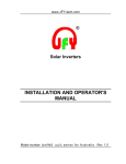
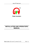
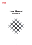
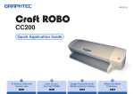
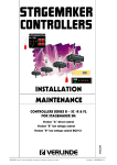
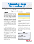
PVCB series Combiner Box User Manual Shenzhen JingFuYuan Tech. Co., Ltd www.jfy-tech.com CONTENT 1 PRODUCT DESCRIPTION .................................................................................................... 3 1.1 OVERVIEW......................................................................................................................... 3 1.2 SCOPE OF SUPPLY ............................................................................................................. 3 1.3 MODEL DESCRIPTION ......................................................................................................... 3 1.4 FUSE RATING SELECT HELP ................................................................................................ 4 1.5 DC CIRCUIT BREAKER RATING SELECT HELP........................................................................ 4 1.6 FEATURES ......................................................................................................................... 4 1.7 WORK ENVIRONMENT ........................................................................................................ 5 2 BASIC STRUCTURE ............................................................................................................. 5 3 INSTALLATION AND OPERATION ...................................................................................... 6 3.1 BASIC INSTALLING REQUIREMENTS ..................................................................................... 6 3.2 INSTALLATION TOOL TO PREPARE ........................................................................................ 6 3.3 MECHANICAL INSTALLATION METHODS AND PROCEDURES .................................................... 6 3.4 ELECTRICAL CONNECTION .................................................................................................. 7 3.4.1 Waterproof terminals and corresponding cable ....................................................... 7 3.4.2 Preparation before wiring ......................................................................................... 9 3.4.3 DC input and output wiring ...................................................................................... 9 3.4.4 Communication Wiring ........................................................................................... 10 3.5 VIEW COMBINER BOX MONITORING DATA ............................................................................ 11 3.6 COMMUNICATION PARAMETER SETTING ............................................................................. 12 3.6.2 Baud rate setting .................................................................................................... 13 3.6.3 Selection of machine type ...................................................................................... 14 3.7 STOP AND START COMBINER BOX ...................................................................................... 14 4 ROUTINE MAINTENANCE .................................................................................................. 15 4.1 FUSE REPLACEMENT ....................................................................................................... 15 5 SPECIFICATIONS ............................................................................................................... 16 6 TROUBLESHOOTING ......................................................................................................... 17 6.1 COMMON TROUBLESHOOTING METHODS .......................................................................... 17 6.1.1 RS485 communication failure ................................................................................ 17 6.1.2 LIGHTING PROTECTION DEVICE FAILURE ......................................................................... 17 6.1.3 The LED are not displayed .................................................................................... 17 6.1.4 Current sampling problems .................................................................................... 17 7 QUALITY ASSURANCE ...................................................................................................... 18 7.1 WARRANTY POLICY.......................................................................................................... 18 7.2 WARRANTY AND CLAIMS PROCEDURE ............................................................................... 19 1 Product Description 1.1 Overview In a solar photovoltaic system, between PV array and inverter, cables connections, monitoring and maintenance are not convenient as well as other reasons, generally it has to be equipped with a combiner box device. PVCB series combiner box includes both smart and non-smart type, and models range from 8-way, 10-way, 12-way to 16-way. Smart combiner box primarily by the DC circuit breakers, lightning protection, cable interface, the current sampling board, insurance board, communication metering board and auxiliary power board. Current sampling board is using to turn a large current to the small current signal, communication metering board is using to sample each branch line current of combiner box, PV bus voltage sampling, as well as lightning protection devices and circuit breakers state monitoring, It can sample real-time data send to the host computer so that we can monitor the state of voltage and current. Communication metering board provides DIP switches for address selection and the type of machine. non-smart combiner box have not communication metering board, sampling board and auxiliary power supply board, so it do not have the function of sampling voltage, sampling current, lightning protection status detection and the DC circuit breaker status detection. 1.2 Scope of supply Combiner box including: PV array combiner box. Chassis Intrusion keys. User manual. Warranty card. Certificate. Factory test report. 1.3 Model description PVCB-XX M It represents the PV array combiner box. It represents the largest number of parallel inputs of combiner box It represents combiner box has inspection and monitoring functions 1.4 Fuse rating select help In any power system, the fuse is used to protect electronic devices from over-current damage, if without protection, over current may cause electronic devices malfunction, overheat, damage and even fire. If the fuse rating is too large, it cannot provide protection, if the fuse rating is too small, then the circuit cannot work properly. Therefore, we have to select the suitable fuse ratings according to the level of PV array and related standards. The fuses ratings be determined by the short circuit current Isc of the PV array, due to different specifications of solar panels, the short-circuit current Isc are various, the different levels of the fuse have to be replaced to meet requirements of the PV array. If no relevant requirements of local standards, we recommend the maximum current flowing through the fuse is 1.56 * Isc. For example, the PV array short circuit current is 10A, then the maximum rated current of the fuse is 15.6A, and voltage requirements of 1000V, then we can choose 16A/1000V fuse. 1.5 DC circuit breaker rating select help DC circuit breaker for selection depends on the input ones of combiner box and the size of each of the input current, such as 12 way combiner box, assuming short-circuit current Isc of the PV array is 10A, the size of the voltage 1000V, flowing through the DC circuit breaker current of 10 × 12 = 120A. Therefore, the level of the DC circuit breaker must be at least 120A/1000V. 1.6 Features Current measurement using hall sensors, isolation measurements. Special PV DC circuit breakers, lightning protection devices and fuses. Measuring voltage range 0 to 1000V.It can detect lightning protection and breaker status and cabinet temperature. (Non-smart type does not have this feature) With RS485 communication interface, communication protocol is MODBUS protocol. (Non-smart type without this feature) PV power supply for the internal power supply: DC 250-1000V. The communication address can set by DIP switch; you can view the current size of each channel, PV bus voltage, temperature, RS485 communication baud rate, combiner box mailing address and combiner box type. (Non-smart type without this feature) 1.7 Work Environment Operation environment temperature: -25 ℃ ~ +60 ℃. Storage temperature: -40 ℃ ~ +70 ℃. Relative humidity ≤ 99%, non-condensing. No severe vibration shock, vertical gradient ≤ 5 °. 2 Basic Structure Figure 1 Figure 1 is a combiner box of the whole internal structure of miniature, each part of the name of the below table: Part Number Description 1 DC positive output terminal 2 DC negative output terminal 3 Ground terminal 4 RS485 communication terminals (Only for smart type) 5 DC positive fuse holder and fuse (One fuse in series each input string) 6 DC negative fuse holder and fuse (One fuse in series each input string) 7 Communication metering plate (Only for smart type) 8 Lighting protection device 9 DC circuit breaker 10 auxiliary power (Only for smart type) Table 1 3 Installation and Operation 3.1 Basic Installing requirements Although all models of combiner box have an IP65 degree of protection and can be installed outdoors, it is also an electronic device, please try to install the machine in a well ventilated, dry and dust-proof place but not a damp places. Install the combiner box as close as possible to the PV array to reduce the use of cables and get a better convergence. Environment temperature -25 ℃ to +60 ℃, relative humidity of 0% to 99%. Avoid direct rays of the sun; otherwise the high temperatures may reduce the life of the combiner box. Forbidden to upside down the installation. 3.2 Installation tool to prepare Drill, screwdriver, adjustable wrench, socket wrench (M9) and so on. 3.3 Mechanical installation methods and procedures Combiner box wall-mounted on solar panel bracket, you need to configure the hex bolts (R4.5), flat washers (R4.5), spring washers (R4.5). Users can also base on specific installation conditions to choose suitable bolts. Below taking 12 Way combiner box as an example to explain the steps to install, other models of combiner box installation steps are same, but not the same size. Installation steps: (1) Combiner box installing to bracket of solar panel needs to meet the following size (unit mm), shown in Figure 2: Figure2 (2) With a hex nut and hex bolts fix combiner box, it is the bolt, combiner box hangers, brackets, flat washers, spring washers and nuts from bottom to top by sequence. (3) Check if the combiner box is installed correctly and firmly. 3.4 Electrical connection If the actual access of the PV array is smaller than the largest connected ones, the extra terminals need to use waterproof plug plugged. Each input string is equipped with a dedicated photovoltaic fuses, as the front input protection device, testing each string between positive and negative voltage is between 0 ~ 1000V before inserting the fuse, and ensuring that each PV string has no fault to ground 3.4.1 Waterproof terminals and corresponding cable Description: 8-way, 10-way, 12-way smart and non-smart combiner box waterproof terminals and wiring cable specifications are the same. Except 16-way combiner box waterproof DC bus output terminal and the output of the DC bus connection cables. Figure3 Figure 3 is a 12-way smart combiner box waterproof terminals and the corresponding cable diagram, non-smart combiner box but less waterproof RS485 communication terminals. 8-way, 10-way, 12-way smart and non-smart type combiner box, user can choose the appropriate wiring cables according to Table 2. Terminal Description Terminal Specification Wiring Recommendation DC positive input (PV + IN) PG7 4mm² DC negative input (PV -IN) PG7 4mm² DC positive bus output (PV + OUT) PG21 50mm² DC negative bus output (PV + OUT) PG21 50mm² Ground terminal PG11 16mm² Communication Terminals PG7 1.5mm ² low resistivity shielded twisted pair Table 2 16-way smart and non-smart type combiner box, user can choose the appropriate wiring cables according to Table 3. Terminal Description Terminal Specification Wiring Recommendation DC positive input (PV + IN) PG7 4mm² DC negative input (PV -IN) PG7 4mm² DC positive bus output (PV + OUT) PG21 70mm² DC negative bus output (PV + OUT) PG21 70mm² Ground terminal PG11 16mm² Communication Terminals PG7 1.5mm ² low resistivity shielded twisted pair Table 3 Description: different cable manufacturers will have some differences, diameter is different according to the solar panel, but it should be matched with the waterproof terminals. Shown in Figure 3, with 12-way combiner box as an example to explain the terminal situations: on the left PV + IN is the wiring hole for DC positive of the PV array ,on the right PV-IN is the wiring hole for DC negative of the PV array. In middle PV + OUT is the wiring hole for DC positive bus output, PV-OUT is the wiring hole for DC negative bus output ,with earth symbol is the wire hole for the grid ground. RS485 communication ports with RS485 label left one which is connected to a previous combiner box, the right one is connected to the next combiner box. 3.4.2 Preparation before wiring (1) Open combiner box All PV array combiner box offers a key to close and open it. Please put the key into the lock, twisting the key as the direction shown in Figure 4. Clockwise twist close the box, counterclockwise twist open the box, Attention: you must turn on / off both up and down, in order to turn on or off the box effectively. Figure 4 (2) Off the circuit breaker in "OFF" position. (3) Remove all fuses, if the fuse is not installed by factory, skip this step. (4) Using a dedicated pliers pull out all the fuses, electrical pliers insulation voltage greater than 1000V. 3.4.3 DC input and output wiring Attention: The PV strings presence of high voltage, accidental exposure may produce lethal electric shock or burns, need to pay attention the following security when wiring: While wiring, please cover the PV arrays by opaque material. Please follow safety instructions of all solar panel manufacturers’. Wiring must be correct, note the distinction between positive and negative, confirming that no ground fault. Recommended wiring to bring an insulation gloves, insulated voltage greater than 1000V. Connection steps: (1) Loosen the lower end of the combiner box locking packing cap. (2) The cables of line number PV1 + through the PV array positive input terminal, access combiner box corresponding to the PV1 + terminals. Note line to leave a margin in order to fix. (3) With a wire poke insulation stripper layer and shielding layer, partially exposed copper wire about 12mm. (4) Use a cross screwdriver to loosen the captive terminal, insert the cable into the terminal, tighten the screws. (5) By the same method to connect the remaining lines, the wiring preferably correspond to the order to the corresponding terminals so that the maintenance of late. 3.4.4 Communication Wiring Description: non-smart combiner box have not this step. The network of combiner box by RS485 communication connecting is shown in Figure 5. Figure 5 Note: Figure 5 shows the final combiner box need to pick a 120Ω resistor, just put J2 plug with the jumper on communication metering board, the 120Ω resistor is connected to the RS485 bus. Figure 6 Part 1 2 3 4 Description RS485 communication terminal DC positive bus output terminal Grid ground terminal DC negative bus output terminal Table 4 As Figure 6 shows the internal terminal block of combiner box, from left to right, they are RS485 communication terminals, DC positive bus output terminal, ground terminal, DC negative bus output terminal. Wiring must take on the right line, or else will cause very serious consequences. RS485 communication terminals is divided into two groups ,a total of six interface shown in Figure 6, from left to right is A1,A2, B1, B2, G1, G2, in which A1, B1,G1 is a group, A2, B2, G2 as a group. 3.5 View combiner box monitoring data Description: non-smart combiner box does not have this feature. Figure 7 LED display Introduction 8-way smart combiner box 10-way smart combiner box 12-way smart combiner box 16-way smart combiner box page Display content 1~8 PV DC inputs 1 ~ 8 channel current size(unit A) 9 Voltage (unit V) 10 Temperature (unit℃) 11 RS485 communication address 12 Combiner box model page Display content 1~10 PV DC inputs 1 ~ 10 channel current size(unit A) 11 Voltage (unit V) 12 Temperature (unit ℃) 13 RS485 communication address 14 Combiner box model page Display content 1~12 PV DC inputs 1 ~ 12 channel current size(unit A) 13 Voltage (unit V) 14 Temperature (unit ℃) 15 RS485 communication address 16 Combiner box model page Display content 1~16 PV DC inputs 1 ~ 16 channel current size(unit A) 17 Voltage (unit V) 18 Temperature (unit ℃) 19 RS485 communication address 20 Combiner box model Table 5 Shown in Figure 7, 5 LED display, the front two LED display is used to display pages, following three to sequentially display the current, voltage, temperature, combiner box communication address and combiner box type. Shown in Figure 8, function of the key A1 is to page up, and the key A2 is to page down, can be recycled flip, the display content shown in Table 4. Description: LED display will automatically turn off after three minutes show that only a decimal point, click the button A1 or A2, LED display will resume, so when the LED light is not on ,do not think it is abnormal. 3.6 Communication parameter setting Description: non-smart combiner box type without this feature. Combiner box communication parameters can be set by the dips switches on communication metering board; it includes communication address setting and communication rate setting. Figure 8 Description: non-smart combiner box does not have this feature. Setting address cutline Binary decimal address addres s 1 (1×20=1) 0000 0001 2 (1×21+0×21=2) 0000 0010 3 1 0000 0 (1×2 +1×2 =3) 0011 247 1111 (1×27+1×26+1×25+1×24+0×23+1×22+1×21+1×20=247) 0111 Table 6 Communication addresses setting is shown in Table 5. This communication metering board provides two keys to set communication parameters shown in Figure 8. Function of the key A1 is to page up and the key A2 is to page down, when address set completion, using the keys turn to corresponding page, you can view the address you have set. The address is displayed in decimal. 3.6.2 Baud rate setting Description: non-smart combiner box type does not have this feature. Baud rate refers to the RS485 communication rate, while holding down the A1 and A2, then release the button, the LED display shows the current default baud rate, and then passed through a separate press A1 select the baud rate you want, and then press A2 to finish. The combiner box provides 2400/4800/9600/19200bps four kinds of baud rate for selection. Note: 1 When the communication distance is far, select a lower baud rate, communication will be more stable. 2 Combiner box baud rate must be same with the host computer monitoring software baud rate setting. 3.6.3 Selection of machine type Description: non-smart combiner box does not have this feature. PVCB series combiner box provides 8-way, 10-way, 12-way and 16-way, a total of four models, if you want the content of LED display to be correct, you must select the corresponding machine type by the DIP switch on communicate metering board show in Figure 9 Figure 9 Different machine type setting method as following switch1 switch2 switch3 Machine type 1 0 0 8-way 0 1 0 10-way 1 1 0 12-way 0 0 1 16-way Table 7 Show in Table 7 "1" stands for upward, "0" stands for downward. For example, if combiner box type is 10-way. You just keep switch 1 and switch 3 downward and switch 2 upward, if you want to ensure you choice is correct, you can flip through the key A1 and key A2 buttons scroll to the appropriate page, the machine type will display on LED display. Description: In addition to the above table lists case, LED will display "Err" which indicate the type of machine is wrong. 3.7 Stop and start combiner box Combiner box run automatically after power on, automatically shutdown after power off, you can stop the DC bus output by the DC circuit breaker. 4 Routine Maintenance Due to ambient temperature, humidity and dust factors, so there will be a potential failure, combiner boxes require regular maintenance in order to ensure normal operation and service life. When maintenance is required, combiner box must be stop and ensure that combiner box is total power off. Attention: Fuse has high voltage from solar panels and inverters, during normal working it cannot be touched. Before checking and replacing the fuse, you must disconnect the DC circuit breaker! Please note it is still in high voltage across the DC circuit breakers, until confirm current of each string is zero, we can remove the fuse from the solar panels or combiner box for maintenance. We recommend to wear insulated gloves, insulated voltage greater than 1000V to do the maintenance. 4.1 Fuse Replacement Broken fuse can not be recovered, only an operators with relevant qualifications recommended to replace the fuse. After several plug fuse, the base of fuse will loose, using a plier which insulated voltage is greater than 1000V to fix tight, to ensure a good contact with the base of fuse. 5 Specifications Smart combiner box type Model PVCB-8M PVCB-10M PVCB-12M PVCB-16M 9.6A 9.6A 9.6A 9.6A Communication RS485 RS485 RS485 RS485 Max input voltage 1000V 1000V 1000V 1000V 8 10 12 16 IP65 IP65 IP65 IP65 400*200*420 460*200*470 460*200*470 460*200*590 Parameters Max input current Max input circuit Degree of protection Dimension (W * H * L) mm Table 8 Non-smart combiner box type Model PVCB-8M PVCB-10M PVCB-12M PVCB-16M Max input current 9.6A 9.6A 9.6A 9.6A Max input voltage 1000V 1000V 1000V 1000V 8 10 12 16 IP65 IP65 IP65 IP65 400*200*420 460*200*470 460*200*470 460*200*590 Parameters Max input circuit Degree of protection Dimension (W * H * L) mm Table 9 6 Troubleshooting Attention: Before troubleshooting, please observe these steps to deal with it in order to ensure safety. Before operating the combiner box, the DC breaker must be disconnected Remove all fuses, at this time there are still high voltage on fuse’s base. Recommended to wear insulated gloves which insulated voltage is greater than 1000V. 6.1 Common troubleshooting methods 6.1.1 RS485 communication failure (1) Check if the power supply is normal. RS485 chip supply voltage is 5V voltage. If abnormal, please check the auxiliary power output. (2) Checking PC monitor software whether the address setting is same with the combiner box. (3) Checking PC monitor software whether the baud rate setting is same with the combiner box. (4) Interference from communication lines, check if the communication bus terminal is connected with 120Ω matching resistor. 6.1.2 Lighting protection device failure Check if detection line is secure. If the contact is good, it means lighting protection device failed, you should replace a good one immediately. 6.1.3 The LED has no display Click the button A1 or A2, if the LED does not display, it means something wrong with the LED display circuit. 6.1.4 Current sampling problems If a channel's current sample display value is much larger or smaller than the other one, Please check if the fuse or photovoltaic arrays is work normal. 7 Quality Assurance 7.1 Warranty Policy PV array combiner box provide 60-month warranty period. The accessories have 24-month warranty period. Warranty period beginning: The date which you get the goods from our dealer's. Warranty evidence: the product serial number and the local dealer delivery invoice Range: During the warranty period the occurrence of any damage will be assessed by the dealer and our company defines its scope and responsibilities. Warranty Policy: In order to provide better services to all users, all authorized distributors of our company are required to respond to end users’ warranty claim. During the warranty period , it will be replaced by any authorized dealer in the design and production of defective products and accessories. Under the following situations our company exempted from liability: (1) Product design changes or modifications or replacement parts without permission of our company. (2) Modification, changes or attempted repair and the serial number has been rubbed or without technicians’ seal of our company. (3) Incorrect installation and commissioning. (4) Failure to comply with the appropriate safety regulations (CQC standards, etc.). (5) The product has been improperly stored and damaged while being stored by the end user. (6) Transportation damage, painting surface scratches cased by shipping pumping. When unloading there is sufficient evidence should be reported to the insurance company as soon as possible. (7) Fails to comply with user manuals, installation guides, maintenance procedures. (8) Improper use or improper operation. (9) Lack of ventilation equipment. (10) Associated with this product or performing maintenance procedures not followed an acceptable standard. (11) Force majeure (such as lightning, overvoltage, storms, fires). 7.2 Warranty and Claims Procedure Claim principles: the principle of warranty claims beyond the authority cited, especially for defective equipment damage caused by direct or indirect claims for damages or losses arising from the demolition and installation requirements for compensation, or not included in the warranty for loss of profits, in these situations our company have not statutory obligations. Warranty and claims procedures: Please contact your local dealer of our company with a simple description of the error report for defective equipment. If we agree to replace, we generally depending on the model and age, made an equivalent replacement device. The remaining warranty rights will be transferred to the replacement device. In this case, because of your authority has been filed at our company, you will not receive a new certificate. Replacement products will be send in two working days Defective equipment should return to the dealer. If the on-site service is necessary, the end user should consult in advance with the dealer. All warranty service during the warranty period is free. Shenzhen JingFuYuan Tech.Co.,LTD. ADD:5th Floor, 12th Block, Nangang Second Industrial Park, SongBai Road, Xili Town, Nanshan District, Shenzhen, P.R.China Tel: +86-755-8179 5460 Fax:+86-755-2650 5986 E-mail: [email protected] Website:www.jfy-tech.com