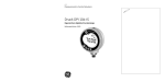
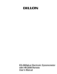
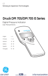
1
GE
Measurement & Control Solutions
Druck DPI 104-IS
Intrinsically safe digital pressure indicator
User manual - K0436
(† 1)
L1
II 1 G Ex ia IIC T4 Ga
L2
Druck,
LE6 0FH, UK
(† 4)
Customer service
B1
Visit our web site: www.gesensinginspection.com
1180
(-10°C ≤ Ta ≤ +50°C)
ITS07ATEX25517X
(† 2)
IECEx ITS 07.0007X
WARNING: REPLACE BATTERY
IN SAFE AREA ONLY
***** **** ** (20 bar g)
(† 5)
DoM: mm/yy (06/07)
(† 6)
S/N. *******
(† 7)
(† 3)
B2
A1.1
RS232 (Rx)
RS232 (Tx)
GND
+VE
A1.2
GND
ALARM
SWITCH
NC
L1, L2
Ui
(V)
1
A2
A1.3
2
3
5
6
4
9
A2
13
12
14
11
16
15
K0436 Iss. 2
10
Pi
(mW)
Ci
Li
1.6 µH
S2-S1
+VE
16.9
22
210
0
S2-S6
ALARM
16.9
22
210
0.1 nF
0
S2-S7
SWITCH
0
0
0
0
0
S2-S3
RS232 (Tx)
16.2
4.75
210
440 nF
0
S2-S4
RS232 (Rx)
16.2
4.75
210
440 nF
0
Uo
(V)
Io
(mA)
Po
(mW)
Co
Lo
0
0
7
8
Ii
(mA)
S2-S1
+VE
0
0
0
S2-S6
ALARM
5
0.5
0.69
99.9 µF
S2-S7
SWITCH
5
6.75
8.5
100 µF
1H
S2-S3
RS232 (Tx)
10
14
260
2 nF
0.41 H
S2-S4
RS232 (Rx)
10
14
260
2 nF
0.41 H
1H
Quick Reference
WARNING: Before using this instrument, read and understand the “Safety” section. It
is dangerous to ignore the specified warnings.
Power on sequence
1
First display =
FS limit
Then:
Normal output
Power off sequence
Normal output
1
Menu:
2
OFF
Press and hold
Change the pressure units
Normal output
1
Menu:
2
Menu:
OFF
mbar
3
Menu:
Press and hold
4
psi
mbar
Normal output
psi
Set the DPI 104-IS to zero
Normal output
Normal output
donE
Press and hold
[EN] English - K0436 Issue 2
Tare = 70 mbar
1
Menu sequence
Menu Description
Steps
[Options]
1
OFF
= Power supply off:
Page 1/7. [OFF]
unitS
= Set units: 24/11.
[A2: item 14]
t On
= Set tare (or set zero):
Page 1/12. [On or OFF,
On + value]
OFF
= Monitor
maximum/minimum:
Page 13. [On or OFF]
OFF
= Monitor a pressure
switch: Page 13.
[On or OFF]
C _ _ _ _ = Calibration: Page 20.
A OFF
2
-
Menu Description
Steps
[Options]
1
Au On
= Set automatic power
OFF: Page 16. [OFF, On +
value]
L OFF
= Set lock code: Page 16.
[OFF, On + value]
Sc 02
= Set scan rate: Page 17.
[value]
FS ↓
= Set FSO low register:
Page 17. [value]
FS ↑
= Set FSO high register:
Page 17. [value]
2
Normal
display
= Set low/high alarm:
Page 14. [OFF, On +
value]
(Continued)
2 Quick Reference
K0436 Issue 2 - [EN] English
Table of Contents
Front cover:
L1/L2: Explosion protection markings
A1: Parts of the instrument/battery access
A2: Parts of the display
B1: Permitted bezel/connector angles
B2: Maximum permitted electrical values
Quick Reference ............................................ 1
Power on sequence ............................................. 1
Power off sequence ............................................ 1
Change the pressure units ............................... 1
Set the DPI 104-IS to zero ................................. 1
Menu sequence ..................................................... 2
Table of Contents .......................................... 3
Introduction ................................................... 4
Safety .............................................................. 4
Special conditions for safe use ...................... 5
Marks and symbols ............................................. 5
To Start ........................................................... 6
Key to figure A1 (Instrument) .......................... 6
Key to figure A2 (Display) .................................. 7
Prepare the instrument ..................................... 7
Power on or off ...................................................... 7
Menu operation ..................................................... 8
Installation ..................................................... 9
DPI 104-IS battery ................................................ 9
DPI 104-IS position .............................................. 9
Pressure connections ...................................... 10
Electrical connections ..................................... 11
Operation .................................................... 11
Menu: Set units .................................................... 11
Menu: Set tare (or set zero) ............................ 12
Menu: Monitor maximum/minimum ......... 13
Menu: Monitor a pressure switch ............... 13
Menu: Calibration ............................................... 14
Menu: Set low/high alarm .............................. 14
Menu: Set automatic power OFF ................ 16
Menu: Set lock code .......................................... 16
Menu: Set scan rate .......................................... 17
Menu: Set FSO low/high registers .............. 17
Software connections ...................................... 18
Error indications ................................................. 19
Maintenance ............................................... 19
Replace the batteries ....................................... 19
Restore the original configuration ............. 19
Calibration .................................................. 20
Equipment and conditions ............................ 20
Procedures ............................................................ 20
Specification ............................................... 23
General ................................................................... 23
Electrical ................................................................. 23
Pressure measurement .................................. 24
EC Declaration of conformity ...................A-1
Approvals - ATEX.........................................B-1
Approvals - IECEx ...................................... B-9
Customer service ......................... Back cover
© 2010 General Electric Company. All rights
reserved.
Trademarks
All product names are trademarks of their respective
companies.
[EN] English - K0436 Issue 2
3
Introduction
The data that follows applies to the Druck DPI 104-IS with the
specified marking details. Refer to Marks and Symbols.
The Druck DPI 104-IS digital pressure indicator measures the
pressure of liquid, gas or vapour and shows the pressure value on
a liquid crystal display (LCD). The DPI 104-IS is designed to operate
in the “hazardous areas” specified by the certification markings
(Refer to “Marks and symbols”).
Note: In this document, “hazardous areas” includes potentially
explosive atmospheres, hazardous (classified) locations, explosive
gas atmospheres.
The DPI 104-IS includes these functions:
Function
* Measure pressure - Accuracy: 0.05% full-scale (FS)
Large 5-digit main display with 11 pressure units
Adjustable Full-Scale Output (FSO)
20 segment analogue dial in increments of 5% FSO
(large division marks = 10% increments).
2.5 digit percentage indicator (0-100% FSO)
8-pin connector port: For RS232, external power supply
Alarm output for high/low pressure conditions
Switch input to monitor an external pressure switch
Other functions: Maximum/minimum, tare, automatic power off
* Refer to Specifications.
Safety
Before installing and using the DPI 104-IS, read and understand all
the related data. This includes: all local safety procedures and
installation standards (for example: EN 60079-14), and this
document.
WARNING
•
Do not open the DPI 104-IS when an explosive atmosphere is
present - this can cause an explosion.
•
Do not use tools on the DPI 104-IS that might cause
incendive sparks - this can cause an explosion.
•
Do not connect an energised electrical circuit in a
hazardous area while explosive atmospheres are present this can cause an explosion. Isolate the power supply to the
equipment first.
Continued
4
Introduction/Safety
K0436 Issue 2 - [EN] English
Safety (Continued)
•
Batteries can cause incendive sparks. Install the battery in a
safe area only. Use only Duracell® Procell® MN1604.
•
Some liquid and gas mixtures are dangerous. This includes
mixtures that occur because of contamination. Make sure
that the DPI 104-IS is safe to use with the necessary media.
•
It is dangerous to ignore the specified limits for the
DPI 104-IS or to use the DPI 104-IS when it is not in its
normal condition. Use the applicable protection and obey
all safety precautions.
•
To prevent a dangerous release of pressure, isolate and
bleed the system before disconnecting a pressure
connection.
Note: In this document, a “safe area” includes non-hazardous
location, unclassified area.
To install and use the DPI 104-IS in a hazardous area, use only
approved engineers who have the necessary skills and
qualifications.
Special conditions for
safe use
When the power supply for the DPI 104-IS is through the 8-pin
connector, use only a Type A or a Type B cable as specified in IEC
60079-14.
Marks and symbols
Refer to figures L1 and L2 to see the certificate details related to
explosion protection.
Notes (†):
(† 1) ATEX certification markings
(† 2) IECEx certification markings
(† 3) Warning text:
WARNING: REPLACE BATTERY IN SAFE AREA ONLY
(† 4) Name and address of the manufacturer
(† 5) Pressure range. Example: 20 bar g
(g: gauge; a: absolute; sg: sealed gauge)
(† 6) Date of manufacture (month/year)
(† 7) Serial number for the instrument
[EN] English - K0436 Issue 2
Introduction/Safety 5
Other marks and
symbols
Complies with European Union directives
Warning - refer to the manual
Do not dispose of this product as household waste. Refer to
Maintenance.
To Start
Key to figure A1
(Instrument)
Table 1: Key to figure A1
Item
1.
2. •
•
•
•
3.
Menu mode: Press and hold to show the first menu option. To
move down the menu structure, press again and again, or
continue to press and hold.
Reject or stop the change to a value.
In maximum/minimum mode. Press to show the maximum and
minimum values since the last reset.
= maximum
= minimum
In menu mode:
- On/OFF selection
- Increase/decrease a value
4.
5. •
•
•
6.
7.
8.
9.
10.
Description
8-pin connector for external power supplies, RS232 connections
and signal input/output.
Power on button
- Move the decimal left/right
Pressure sensor and connector with 320° of turn: gauge (g),
absolute (a) or sealed gauge (sg). Refer to Specification.
In menu mode:
- Accepts a menu selection
- Accepts a value
- Shows the next menu level
In Tare mode: Set the pressure value on the display to zero.
In maximum/minimum mode. Reset the maximum/minimum
values.
Display bezel with 348° of turn.
O-ring.
Battery connector
Battery: Supplied but not installed; refer to Installation.
Battery cover/clamp with two screws and a label:
REPLACE BATTERY IN SAFE AREA ONLY
USE ONLY DURACELL PROCELL MN1604
REMPLACEZ LES PILES UNIQUEMENT
EN ZONES NON-DANGEREUSES.
UTILISER UNIQUEMENT LE MODELE
DURACELL PROCELL MN1604
6
Start
K0436 Issue 2 - [EN] English
Key to figure A2
(Display)
Table 2: Key to figure A2
Item
11.
12.
13.
14.
The units of measurement: kPa, MPa, kg/cm2, psi, mbar, bar,
mmHg, mmH2O, mH2O, inH2O, inHg
15.
Mode indication.
RS232 connection. The data transmit/receive function is active.
Switch mode - On. To monitor an external pressure switch.
= switch closed
= switch open
Menu Lock mode - On. To restrict access to the menu functions.
16.
Prepare the instrument
Power on or off
Description
5-digit main display.
2.5-digit percentage indicator (0-100% FSO).
%FSO = [Applied Pressure/(FSOHigh—FSOLow)] * 100
20 segment analogue dial in increments of 5% FSO
(large division marks = 10% increments).
%FSO = [Applied Pressure/(FSOHigh—FSOLow)] * 100
Alarm mode - On. The symbol flashes when the measured value
satisfies one of the alarm conditions.
= High alarm
= Low alarm
Maximum/minimum mode - On.
Low battery power indication: Battery life ≤ 15%.
Before using the instrument for the first time:
•
Make sure that there is no damage to the instrument, and that
there are no missing items.
•
Install the battery (refer to Installation). Then re-attach the
display bezel [A1: item 6].
Refer to Quick Reference.
When the power is off, the last set of configuration options stays in
memory.
Note: The DPI 104-IS uses a small quantity of power while it is OFF.
If placing in storage for a long period, disconnect the battery (refer to
“Installation”).
[EN] English - K0436 Issue 2
Start 7
Menu operation
Menu Description
Steps
1
2
OFF
= Power supply: OFF only
unitS
= Set units: (A2: item 14).
Pressure value changes to the applicable units:
psi, mbar, bar ...
t On
= Set tare (or set zero): Set to
On or OFF.
On ➤ tA 00.000 : Set a tare value (Refer to Table 6)
= Monitor
maximum/minimum:
Set to On or OFF
Monitor function is set on or off
= Monitor a pressure switch:
Set to On or OFF.
Monitor function is set on or off
OFF
OFF
C _ _ _ _ = Calibration: To continue, set
the correct calibration
access code = last four digits
of S/N. *******
-
Result/Subsequent steps
Power goes off
C0 (Correct the zero offset value) ➤
C2 (Do a two-point pressure calibration) . Refer to
Calibration.
A OFF
= Set low/high alarm: Set to
On or OFF.
On ➤ 000.0 ↓ ➤ 100.0 ↑
Set a value for the low and/or high alarm (0 to
105% FSO).
Au On
= Set automatic power OFF:
Set to On or OFF.
On ➤ Au 15 : Set the period for automatic power
OFF (1 to 99 minutes). Factory value = 15 minutes.
L OFF
= Set lock code: A menu
protection facility. Set to On
or OFF.
On ➤ L 000 : Set a new lock code (if necessary).
Factory code = 000.
Sc 02
= Set scan rate: A rate that
the DPI 104-IS uses to take
pressure samples.
Set an applicable rate (02 to 10 Hz).
Factory value = 02 Hz.
FS ↓
= Set FSO low register: To set
a different range for these
functions: analogue display,
%, alarm.
Set a value for the low end of the range (refer to
Table 7).
Factory value = Factory calibration value.
FS ↑
= Set FSO high register: To set
a different range for these
functions: analogue display,
%, alarm.
Set a value for the high end of the range (refer to
Table 7).
Factory value = Factory calibration value.
Normal display
8
Menu operation
K0436 Issue 2 - [EN] English
Installation
This section shows how to install and connect the DPI 104-IS.
Before starting:
•
Read and understand the Safety section.
•
Do not use a damaged DPI 104-IS.
The materials that are used in the DPI 104-IS are specified in the
Specification section. Make sure that the materials are applicable
for the installation.
DPI 104-IS battery
To install the battery follow the procedures in Table 3.
WARNING: Batteries can cause incendive sparks. Install the
battery in a safe area only. Use only Duracell® Procell® MN1604.
Table 3: Installation procedures - Battery
Step
1
2
3
4
5
6
7
Procedure
If applicable, set the power to off and isolate the external
power supply.
Figure A1.2: Remove the display bezel ( ➀, ➁ ) and the battery
cover/clamp (➂).
Make sure that the o-ring [A1: item 7] and the related surfaces
are serviceable. Use only original parts supplied by the
manufacturer.
If applicable, disconnect the battery connector [A1: item 8] and
*discard the used battery.
Attach the battery connector [A1: item 8] to the new battery.
Install the new battery (Figure A1.3) and re-attach the battery
cover/clamp [A1: item 10].
Push the display bezel [A1: item 6] back into position until it is
fully engaged.
* Use an applicable recycling facility.
DPI 104-IS position
[EN] English - K0436 Issue 2
Attach the DPI 104-IS in a safe configuration that prevents
unwanted stress (for example vibration, physical impact, shock,
mechanical and thermal stresses). Do not install the equipment
where it can be damaged by a material that causes corrosion.
Provide additional protection for equipment that may be damaged
in service.
Installation 9
To get the best installation position, turn the pressure connector
(A1: item 4) and the display bezel (A1: item 6) to give the best view of
the display (Figure B1). End stops set the limits in each axis.
CAUTION: To prevent damage when setting the best view of the
display, do not use force to turn the pressure connector or the
bezel farther than the end stops.
Pressure connections
CAUTION: To prevent damage, do not use the body of the
DPI 104-IS to tighten the pressure connection. Use the flat faces
on the pressure connector.
Use an applicable method to seal the pressure connections, and
then tighten to the applicable torque (Figure 1 and Table 4).
1
a) 1/4 NPT:
Pressure < 1000 bar (15000 psi)
2
1
b) G1/4:
Pressure < 1000 bar (15000 psi)
3
1
c) 9/16 x 18 UNF cone:
Pressure ≥ 1000 bar (15000 psi)
Figure 1: Connection methods
Table 4: Key to figure 1
Item
1.
2.
3.
10 Pressure connections
Description
Applicable DPI 104-IS pressure connector. Maximum torque:
1/4 NPT: 68 Nm (50 lbf.ft)
G1/4: 20 Nm (15 lbf.ft)
9/16 x 18 UNF cone: 34 Nm (25 lbf.ft)
(1/4 NPT only) Thread with an applicable sealant
(G1/4 only) Applicable bonded seal
K0436 Issue 2 - [EN] English
Electrical connections
The DPI 104-IS includes an 8-pin electrical connector (A1: item 1).
Table 5 shows the pin connections.
Table 5: Connections for the 8-Pin connector
Connector
Pin
1.
2.
3.
4.
5.
6.
7.
8.
Input/
Output
Input
Input
Output
Input
Output
Input
-
Description
15 Vdc power supply (+VE)
Signal ground (GND)
RS232 transmit (Tx)
RS232 receive (Rx)
Signal ground (GND)
Alarm output (ALARM)
Pressure switch input (SWITCH)
No connection (NC)
Make sure the connections to the DPI 104-IS are from intrinsically
safe (IS) safety barriers or an IS supply.
Figure B2 gives the maximum permitted input and output values.
Connect the earth/ground connections that are applicable to the
installation. If applicable, make sure that the cable screen is
isolated from the DPI 104-IS.
The DPI 104-IS is resistant to an AC test voltage of 500 V RMS as
specified in EN 60079-11.
External power
Operation
We recommend an external power supply for these functions and
operations:
•
Functions: Maximum/minimum, switch, low/high alarm.
•
Operations that use the DPI 104-IS for long periods.
This section shows how to use the DPI 104-IS. Before starting:
•
Read and understand the Safety section.
•
Make sure that the installation is complete (refer to the
Installation section).
•
Do not use a damaged DPI 104-IS.
Menu: Set units
There are 11 different units to measure pressure (refer to the
Specification section).
Units - Set-up
Refer to Quick Reference.
[EN] English - K0436 Issue 2
Operation 11
Menu: Set tare (or set
zero)
Use the tare function to adjust the pressure value on the display.
For example: To make an adjustment for atmospheric pressure
(refer to Table 6).
Table 6: Permitted tare values
Range
g: 0.7 bar (10 psi)
a, sg, g: ≥ 2 bar (30 psi)
Permitted tare values
-0.7 bar (-10 psi) to 105% FS
-1 bar (-15 psi) to 105% FS
Setting a value that is not in the permitted range, the value goes
back to the last accepted value.
Tare - Set-up and use
Menu: Set this function to On (refer to Menu Operation).
When this function is On, there are two options to set a
tare value (tA):
•
Menu option: Set the menu “t On”, then set a tA value:
1 2
tA display
tA display
0 to 9, or -
0 to 9
Repeat steps 1 + 2 for each digit and for the decimal point.
•
Zero option: Step 1 sets a value for tA. Press and hold.
Normal
output
Normal
output
1
donE
tA = 0
tA = 70 mbar
When tA is not zero, the last segment on the analogue dial flashes.
To make sure that there is an indication of the correct pressure
while tare is On, the analogue dial and % indication show values
calculated from the calibrated range without the tare adjustment.
Tare - With lock
12
Operation
If the menu lock is On with a lock code set < 500, the zero option is
rejected - Error code (E0002).
K0436 Issue 2 - [EN] English
Tare - With alarm
Use the zero option to set a tare value (tA) while the alarm is On, the
display counts down from: tArE9 to tArE0.
To cancel the specified tA value, press this button.
To continue with the specified tA value, press this button OR
let the count complete.
Set a tA value, the alarm function uses values calculated from the
calibrated range and the pressure value on the display.
Tare - With FSO values
To make sure that there is an indication of the correct pressure
while tare is On, the FSO Low and/or FSO High values are not used.
Menu: Monitor
maximum/minimum
Use this function to monitor the maximum and minimum pressure.
It uses the specified scan rate (refer to Menu:Set scan rate).
To save battery power (recommended), use an external power
supply with this function.
Maximum/minimum Set-up and use
Menu: Set this function to On (Refer to Menu operation).
When this function is On, use steps 1 + 2 to show the
maximum/minimum since the last reset.
1
maximum
2
minimum
3
donE
Reset
Step 3 resets the values for maximum/minimum. Press and hold.
Menu:
Monitor a
pressure switch
Use this function to measure the performance of a pressure switch
(mechanical operation and hysteresis). It uses the specified scan
rate (refer to Menu:Set scan rate).
To save battery power (recommended), use an external power
supply with this function.
[EN] English - K0436 Issue 2
Operation 13
Pressure switch input Set-up and use
1. Connect the DPI 104-IS (Figure 2/Table 5).
2. Menu: Set this function to On (refer to Menu operation).
Pin 1 (+VE), Pin 2 (GND)
15 Vdc
0 Vdc
Pin 7 (SWITCH)
Pin 2 (GND)
Figure 2: Example configuration - Switch input
Figure 2 shows the display when the switch condition changes
(open or closed). The analogue dial and the % indication continue
to monitor the normal pressure.
The switch symbol and the value on the main display flash to give
the switch condition and the switch pressure.
To reset the monitor function, press this button.
Menu: Calibration
Refer to the Calibration section.
Menu:
alarm
Use the alarm function to show when the pressure is not in the
specified limits for the system.
Set low/high
Set applicable values in the range 0 to 105% FSO:
%FSO = [ Applied Pressure / (FSO High — FSO Low) ] * 100
Note: Setting a tare value, the alarm function uses the calibrated
range and the pressure value on the display (Refer to Menu: Set tare
(or set zero)).
The alarm indication is available on the display and as a signal
output (Table 5). Figure 3 shows an example configuration.
14 Operation
K0436 Issue 2 - [EN] English
Pin 1 (+VE), Pin 2 (GND)
15 Vdc
0 Vdc
Pin 6
(ALARM)
Power
supply
Figure 3: Example configuration - Alarm output
While there is an alarm condition, the applicable alarm symbol
(high or low) flashes on the display (A2: item 15).
To save battery power (recommended), use an external power
supply with this function.
Low/high alarm - Set-up
and use
Menu: Set this function to On (refer to Menu operation). Then use
these steps to set the low and/or high alarm.
Alarm
(% FSO)
Digit = 0 or 1
1
2
Alarm
(% FSO)
3
4
Digit = 0 to 9
5. To finish, repeat steps 3 + 4 for each digit.
If the entered value is not correct, the value resets to the nearest
permitted value. That is:
•
a value in the range 0 to 105% FSO
•
a low alarm value < high alarm value
To accept or change the new value, repeat steps 1 to 5.
To cancel the new value, press this button.
[EN] English - K0436 Issue 2
Operation 15
Menu: Set automatic
power OFF
Use this function to save battery power. The power goes off a
specified period after the last button or external software
operation. To get the maximum battery life, use (recommended)
this function.
Note: The DPI 104-IS uses a small quantity of power while it is OFF.
If putting in storage for a long period, disconnect the battery (refer to
Installation).
Automatic power OFF Set-up and use
Menu: Set this function to On. Then set an applicable value in the
range 1 to 99 minutes (refer to Menu operation).
Note: If continuous operation is important, set this function to OFF
and use an external power supply.
Menu:
Set lock code
Use the lock function to prevent accidental changes to the
configuration. There are two options:
•
Lock code < 500: This locks the menu and the tare function.
Factory code = 000.
•
Lock code > 499: This locks the menu but still use the zero
option to set a tare value.
Refer to Menu: Set tare (or set zero).
Lock code - Set-up and
use
Menu: Set this function to On (refer to Menu operation). Then use
these steps to set a new code.
Lock
Digit = 0 or 9
1
2
Lock
Digit = 0 to 9
3. To finish the lock code, repeat steps 1 + 2 for each digit.
The next change to the menu options, the display shows: L - - Enter the applicable code. To reset the code to the factory code, do
a restore operation (refer to Maintenance).
16 Operation
K0436 Issue 2 - [EN] English
Menu: Set scan rate
This function sets the rate that the DPI 104-IS uses to take pressure
samples from the internal sensor.
The nominal update rate for the display is 2 Hz. The update rate for
the maximum/minimum function and the switch function is greater
than or equal to the specified scan rate.
Note: Increasing the scan rate, increases the power consumption.
Scan rate - Set-up and
use
Menu: Set an applicable value in the range 2 to 10 Hz (refer to Menu
operation).
Menu: Set FSO
low/high registers
Use the FSO low/high registers to set a different range for these
functions: analogue display, % indication, low/high alarm.
Initially, these register values are set to the factory calibration
values. Example:
Calibrated range: 0.7 bar (10 psi) gauge.
Selected units: mbar
FSO low
FSO high
0 bar (0 psi)
700 mbar (10 psi)
Table 7 gives the permitted alternative values that can be used.
Table 7: Permitted FSO values
Range
All ranges: a, sg
g: 0.7 bar (10 psi)
g: ≥ 2 bar (30 psi)
All ranges
[EN] English - K0436 Issue 2
Permitted FSO values
0 to 105% FS
-0.7 bar (-10 psi) to 105% FS
-1 bar (-15 psi) to 105% FS
FSO low < FSO high
Operation 17
FSO low/high registers Set-up and use
Menu: Set the menu option to the FSO low register (refer to Menu
operation). Then use these steps to set an applicable value in the
permitted range (Table 7):
FSO low
1
0 to 9, or -
2
FSO low
0 to 9
3. Repeat steps 1 + 2 for each digit and for the decimal point.
If the value entered is not correct, the value resets to the nearest
permitted value (Table 7).
To accept or change the new value, repeat steps 1 to 3.
To cancel the new value, press this button.
4. If necessary, repeat the procedure for the FSO high register.
Software connections
Use external software with the DPI 104-IS: SiCal PRO monitor and
control software; Intecal calibration software. To use this RS232
function, the DPI 104-IS must have connections to an external
power supply (Figure 4/Table 5).
Pin 1 (+VE), Pin 2 (GND)
15 Vdc
0 Vdc
PC: 9-way, D-type
connector
GND
Tx Rx
Figure 4: Example configuration: RS232
Using SiCal PRO, all the menu commands and display data are
available.
Note: To use SiCal PRO, it must have the serial number for each unit
in use with (DPI 104-IS, IDOS UPM, PC6-IDOS). Please supply the
necessary serial numbers with an order or contact us at
www.gesensinginspection.com.
When the DPI 104-IS transmits or receives data, it shows
this symbol.
18 Operation
K0436 Issue 2 - [EN] English
Error indications
Table 8: Error codes/indications
Code
E0001
E0002
Description
Incorrect unlock code. Use the correct code.
The tare facility is not available because the menu lock is On and
the lock code < 500. Change the menu configuration.
E0004 Start up error. Do a restore operation (refer to Maintenance).
E0006 Incorrect calibration access code. Use the correct code.
E0007 The power supply is too low to do a calibration. Use an external
power supply or replace the battery.
OLoAd Applied pressure ≥ 110% FS. Reduce the pressure.
99999/ There are not enough digits in the main display to give the
-9999 correct pressure value. Change the measurement units.
Maintenance
Clean the case with a moist, lint-free cloth and a weak detergent.
Do not use solvents or abrasive materials.
Make sure that there is no damage to the threads and o-rings, and
that they are free of grit and other obstructions.
Do not try to do repairs to this instrument. Return the instrument to
the manufacturer or an approved service agent.
Do not dispose of this product as household waste. Use an
approved organisation that collects and/or recycles waste
electrical and electronic equipment.
For more information, contact one of these:
•
our customer service department
(Contact us at www.gesensinginspection.com).
•
your local government office.
Replace the batteries
To replace the batteries, refer to Installation. All the configuration
options stay in memory.
Restore the original
configuration
If it is necessary to restore the unit to the original factory
configuration, press and hold all four buttons until the display goes
off ( ≈ five seconds). The unit then restarts.
Menu operation shows the factory settings. The lock code is reset
to the factory code (000).
[EN] English - K0436 Issue 2
Maintenance 19
Calibration
Return (recommended) the DPI 104-IS to the manufacturer or an
approved service agent for calibration.
Note: GE can provide a calibration service that is traceable to
international standards.
If using an alternative calibration facility, make sure that it uses
these standards.
Equipment and
conditions
To do an accurate calibration, requires:
•
the calibration equipment specified in Table 9.
•
a stable temperature environment: 20 ±1°C (68 ±2°F).
Table 9: Calibration equipment
Function Calibration equipment
Pressure An applicable pressure standard (primary or secondary) with a
total uncertainty of 0.01% reading or better.
Make the pressure connection to A1: item 4 (refer to
Installation).
Procedures
1. Connect the applicable calibration equipment (Table 9).
2. Menu: Set the menu option to C _ _ _ _ . Then set the
calibration access code = last four digits of the serial number
(refer to Menu operations).
There are two calibration options (Table 10):
Table 10:
Calibration options
Option Description
Set the necessary offset value for the instrument to give the
C0:
correct pressure related to zero:
All ranges g or sg: Zero (bar/psi);
Ranges a: Ambient pressure*
Do a two-point pressure calibration.
C2:
All ranges g or sg: P1 = Zero (bar/psi); P2* = FS
Ranges a: P1* = Ambient pressure; P2* = FS
* adjustable by 5% FS
20
Calibration
K0436 Issue 2 - [EN] English
C0 (Zero offset)
The DPI 104-IS shows these displays:
1. The calibration point to be used for C0. This value is only
adjustable for an absolute type DPI 104-IS (Table 10).
C0 - Gauge = 0000.0
C0 - Absolute
2
8 seconds
C0 - Absolute
3
4
0 to 9
5. Repeat steps 3 + 4 for each digit and for the decimal point. The
value is ignored if it is not in the permitted limits (Table 10).
This value is then used as the Set Point (SP) on the subsequent
displays.
6. This sequence of displays will follow:
C0
Example sequence: Absolute type
The SP value is followed by the measured pressure - Current
Pressure (CP). This sequence continues until the offset value is
accepted or rejected .
7. When the pressure is stable:
To accept the new offset value, press this button. The display
shows “donE”, and then the next calibration option (C2).
To reject the new offset value and move to the next
calibration option (C2), press this button.
The value is ignored if it is not in the permitted limits (5% FS) or if the
CP value is not stable.
C2 (two-point pressure
calibration)
Point 1 (P1) - The DPI 104-IS shows these displays:
1. The calibration point to be used for C2 - Point 1. This value is
only adjustable for an absolute type DPI 104-IS (Table 10).
C2 - Point 1 (Gauge) = 0000.0
C2 - Absolute
8 seconds
[EN] English - K0436 Issue 2
2
C2 - Absolute
3
4
0 to 9
Calibration 21
5. Repeat steps 3 + 4 for each digit and for the decimal point. The
value is ignored if it is not in the permitted limits (Table 10).
This value is then used as the Set Point (SP) for point 1 on the
subsequent displays.
6. This sequence of displays will follow:
P1
Example sequence: Absolute type
The SP value is followed by the measured pressure - CP. This
sequence continues until the point 1 value is accepted or rejected.
7. When the pressure is stable:
To accept the new P1 value, press this button. The display
shows the calibration point C2 - point 2 (C2).
To reject the new P1 value and move to the next menu
option, press this button.
The value is ignored if it is not in the permitted limits (5% FS) or if the
CP value is not stable.
Point 2 (P2) - Use the same steps (1 to 5 above) to set C2 - Point 2.
This is the FS value and it is adjustable for the absolute and gauge
type DPI 104-IS (Table 10).
6. This sequence of displays will follow:
P2
Example sequence: Absolute type
The SP value is followed by the measured pressure - CP. This
sequence continues until the point 2 value is accepted or rejected.
7. When the pressure is stable:
To accept the new P2 value, press this button. The display
shows “donE”, and does a two-point calibration. The
instrument then restarts.
To reject the new P2 value and move to the next menu
option, press this button.
The value is ignored if it is not in the permitted limits (5% FS) or if the
CP value is not stable.
22
Calibration
K0436 Issue 2 - [EN] English
Specification
General
Operating
temperature
Storage temperature
Ingress Protection
Materials
Humidity
Shock/Vibration
EMC
Safety
Approved
Size
Weight
Power supply
Battery life
-10 to 50°C (14 to 122°F)
-20 to 70°C (-4 to 158°F)
IP65 (Dust-tight, jets of water)
Case: Anti-static Acrylonitrile Butadiene
Styrene/Polycarbonate (ABS/PC)
Keypad: Anti-static silicone rubber
O-ring: Nitrile rubber with silicone grease
RS232 socket: Nickel-plated brass
Vent filter: PTFE
Refer also to Media notes.
0 to 95% without condensation
(Def Stan 66-31, 8.6 cat III)
BS EN 60079-11:2007; Def Stan 66-31, 8.4 cat III
BS EN 61326: refer to appendix A
Electrical - BS EN 61010-1:2001;
Pressure Equipment Directive - Class: Sound
Engineering Practice (SEP); hazardous areas (Refer
to appendices: A, B)
Refer to appendices: A, B;
CE Marked
Diameter = 95 mm (3.74 in); Depth = 55 mm (2.2 in)
Typical length (with connector) ≈ 120 mm (4.7 in)
325 g (11.5 oz)
Battery: Duracell® Procell® 9V, Alkaline (MN1604);
OR Use an external 15 Vdc supply
Up to four months for pressure measurements:
Au (power save facility) - On; maximum/minimum,
alarm, switch - All set to OFF
Electrical
Switch input
Alarm output
RS232
[EN] English - K0436 Issue 2
Maximum impedance: 200Ω (mechanical contact
only).
Maximum (mA/V): refer to Figure B2.
Type: Open drain Field Effect Transistor (FET).
Maximum (mA/V): refer to Figure B2.
For: external software
Specification 23
Pressure measurement
Range: gauge (g), absolute (a),
sealed gauge (sg)
bar
psi
Type
0 to 0.7
0 to 10
g*
Resolution
mbar
0.01
psi
0.001
Maximum Working
Pressure (MWP)
bar
psi
0.77
11.2
Media
notes
0 to 2.0
0 to 30
g* or a
0.1
0.001
2.2
32
1
0 to 7.0
0 to 100
g* or a
0.1
0.01
7.7
111.7
2
0 to 20
0 to 300
g* or a
1
0.01
22
319
2
0 to 70
0 to 1000
g* or a
1
0.1
77
1117
2
0 to 200
0 to 3000
sg
10
0.1
220
3190
2
0 to 350
0 to 5000
sg
10
0.1
385
5583
2
0 to 700
0 to 10000
sg
10
1
770
11165
2
0 to 1000
0 to 15000
sg
100
1
1100
15950
3
0 to 1400
0 to 20000
sg
100
1
1540
22330
3
1
* All gauge models can measure negative pressures (not part of the calibrated range)
Media notes:
1. Non-corrosive, non-conductive liquid or non-corrosive, dry gas
2. Media applicable to stainless steel (316)
3. Media applicable to Inconel 625
Accuracy (0 to FS) 0.7 bar (10 psi): 0.15% FS
All ranges ≥ 2 bar (30 psi): 0.05% FS
Units
Pressure
connections
24
Specification
kPa, MPa, kg/cm2, psi, mbar, bar, mmHg, mmH2O, mH2O, inH2O, inHg
Ranges ≤ 700 bar (10000 psi): 1/4 NPT male OR G1/4 male
Ranges > 700 bar (10000 psi): 9/16 x 18 male cone
K0436 Issue 2 - [EN] English
EC Declaration of conformity
A
[EN] English - K0436 Issue 2
A-1
intentionally left blank
A-2
K0436 Issue 2 - [EN] English
Approvals - ATEX
B-1
B
K0436 Issue 2 - [EN] English
[EN] English - K0436 Issue 2
B-2
B-3
K0436 Issue 2 - [EN] English
[EN] English - K0436 Issue 2
B-4
B-5
K0436 Issue 2 - [EN] English
[EN] English - K0436 Issue 2
B-6
B-7
K0436 Issue 2 - [EN] English
[EN] English - K0436 Issue 2
B-8
B-9
K0436 Issue 2 - [EN] English
Approvals - IECEx
For the IECEx certificate (IECEx ITS 07.0007X), visit the IECEx website
at:
www.iecex.com
[EN] English - K0436 Issue 2
B - 10
Customer service
Visit our web site: www.gesensing.com