1
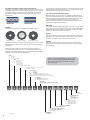
DIN EN 50173-3
Industrial area
DIN EN 50173-1
Office area
DIN EN 50288
Symmetrical cable
DIN EN 60603- 7
Connectors
DIN EN 50288-2- 1
(shielded up to 100MHz)
DIN EN 60603-7- 3
(shielded up to 100MHz)
DIN EN 50288-5- 1
(shielded up to 250MHz)
DIN EN 60603-7- 5
(shielded up to 250MHz)
DIN EN 50288-4- 1
(shielded up to 600MHz)
DIN EN 60603-7- 7
(shielded up to 600MHz)
Cabling standards
Various standards have been set down in international committees
to be independent from manufacturer and system. These divide
into various areas. The international range of validity is set down
in ISI/IEC 11801 and in the national German standard of DIN EN
50173.
DIN EN 50173-2
SoHo
DIN EN 50310
Potenzial Equalization
and Grounding
Part 1
Specification and
Quality Control
DIN EN 50174
Construction and Operation
Part 2
Installation Design and
Practices in Buildings
Part 3
Installation Design and
Practices in Outdoor
• Permanent Link
which covers the laid installation cable and also the patch panel
permanently connected to the end of the cable and the junction
box.
The standard series of EN 50173 is divided into five areas for various applications and covers „application-neutral communication
cablings for information technology".
•
•
•
•
•
EN 50173-1
EN 50173-2
EN 50173-3
EN 50173-4
EN 50173-5
General requirements
Office buildings
Industrially used buildings
Private residential units
Computing centres
There is also a difference in the individual components such as
cables and connection technology and also in the installation of
these components.
• Channel Link
Where the patch cable also used in the patch panel and the junction box can also be measured together with the components of
the Permanent Link.
The individual components are classified into the following
categories:
•
•
•
•
•
Category 5
Category 6
Category 6A
Category 7
Category 7A
up to 100 MHz
up to 250 MHz
up to 500 MHz
up to 600 MHz
up to 1000 MHz
A distinction is drawn between installed components according to
transmission classes
•
•
•
•
•
Class D
Class E
Class EA
Class F
Class FA
up to 100 MHz
up to 250 MHz
up to 500 MHz
up to 600 MHz
up to 1000 MHz
Certification and checking of the limiting values for the measurement technology of the installed transmission routes.
A distinction is drawn between two models for the transmission
routes for the cabling.
38
Defined electrical limiting values give a clear picture of the quality
of the installed system.
• Line length
• With return flow attenuation
• Max. attenuation
• Min. near end cross talk attenuation NEXT
• Min, OSNEXT
• Min. ACR
• Min. PSACR
• Min. ELFEXT
• Min. PSELFEXT
• Max. DC loop resistance
• Max. run time
• Max. run time difference