1
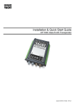
LD2103 V3.0 Page 1 of 45
Instruction Manual
VERSION 1 SmarterTRACK AIT250
Class B Marine Automatic Identification System
Part Number ZDIGAIT250
Doc Ref TU08‐0050 – VR1 Questions? Call the support line 01179 114 111 DIGITAL YACHT LTD
AIT 250 Installation & Operation Manual
General Warnings
All marine Automatic Identification System (AIS) units utilise a satellite based system such as the Global Positioning Satellite
(GPS) network or the Global Navigation Satellite System (GLONASS) network to determine position.
The accuracy of these networks is variable and is affected by factors such as the antenna positioning, how many satellites are
used to determine a position and how long satellite information has been received for.
It is desirable wherever possible therefore to verify both your vessels AIS derived position data and other vessels AIS derived
position data with visual or radar based observations.
The compass safe distance of this unit is 0.5m or greater for 0.3° deviation.
In accordance with a policy of continual development and product improvement the AIT250 hardware and software may be
upgraded from time to time and future versions of the AIT250 may therefore not correspond exactly with this manual.
When necessary upgrades to the product will be accompanied by updates or addenda to this manual.
Please take time to read this manual carefully and to understand its contents fully so that you can install and operate your AIS
system correctly.
Information contained in this manual is liable to change without notice.
FCC Compliance
Use of this equipment on US Flagged vessels is currently not authorised as Class B AIS has yet to be approved by the USCG
This equipment has been tested and found to comply with the limits for a Class B digital device, pursuant to part 15 of the
FCC Rules. These limits are designed to provide reasonable protection against harmful interference in a residential installation.
This equipment generates, uses and can radiate radio frequency energy and, if not installed and used in accordance with the
instructions, may cause harmful interference to radio communications. However, there is no guarantee that interference will not
occur in a particular installation. If this equipment does cause harmful interference to radio or television reception, which can be
determined by turning the equipment off and on, the user is encouraged to try to correct the interference by one or more of the
following measures:
Reorient or relocate the receiving antenna.
•
Increase the separation between the equipment and receiver.
•
Connect the equipment into an outlet on a circuit different from that to which the receiver is connected.
•
Consult the dealer or an experienced radio/TV technician for help.
•
The AIT250 does not contain any user serviceable parts. Repairs should only be made by an authorized Digital Yacht service
agent. Unauthorised repairs or modifications could result in permanent damage to the equipment and void your warranty and
you’re authority to operate this equipment under Part 15 regulations.
RF Emissions Notice
Caution: The AIT250 Class B AIS transponder generates and radiates radio frequency electromagnetic energy. This
equipment must be installed and operated according to the instructions contained in this handbook. Failure to do so
can result in personal injury and / or product malfunction.
Caution: Never operate the transponder unless it is connected to a VHF antenna.
To maximise performance and minimise human exposure to radio frequency electromagnetic energy you must make sure that
the antenna is mounted at least 1.5 meters away from the transponder and is connected to the transponder before power is
applied.
The system has a Maximum Permissible Exposure (MPE) radius of 1.5m. This has been determined assuming the maximum
power of the transponder and using antennas with a maximum gain of 3dBi.
DIGITAL YACHT LTD
•
•
•
•
AIT 250 Installation & Operation Manual
The antenna should be mounted as high above the deck as possible.
Higher gain VHF antennas will require a greater MPE radius.
Do not operate the unit when anyone is within the MPE radius of the antenna (unless they are shielded from the
antenna field by a grounded metallic barrier).
The antenna should not be collocated of operated in conjunction with any other transmitting antenna.
This device has been designed to operate with the supplied antenna or any standard marine VHF antennas having a maximum
gain of 3dBi. Antennas not included in this list or having a gain greater than 3dBi are strictly prohibited for use with this device.
The required antenna impedance is 50 ohms.
Licensing and Maritime Mobile Service Identity (MMSI)
IMPORTANT: In most countries the operation of an AIS unit is included under the vessel's marine VHF licence provisions. The
vessel on to which the AIS unit is to installed must therefore possess a current VHF radiotelephone licence which lists the AIS
system and the vessel Call Sign and MMSI number.
An MMSI number is required in order for the AIT250 transponder to operate.
Please contact the relevant authority in your country for more information.
DIGITAL YACHT LTD
AIT 250 Installation & Operation Manual
Product Specification
Parameter
Value
Dimensions
190 x 135 x 83 mm (L x W x H)
Weight
1450g
Power
DC (10.8 - 15.6V)
Average power consumption 4W
Peak current rating 2A
GPS Receiver (AIS Internal)
IEC 61108-1 compliant
Electrical Interfaces
RS232 38.4kBaud bi-directional
RS422 NMEA 38.4kBaud bi-directional
Connectors
VHF antenna connector
GPS antenna connector
RS232/RS422/Power
VHF Transceiver
Transmitter x 1
Receiver x 2 (One receiver time shared between AIS and DSC)
Frequency: 156.025 to 162.025 MHz in 25 kHz steps
Output Power
33dBm ± 1.5 dB
Channel Bandwidth
25kHz
Channel Step
25kHz
Modulation Modes
25kHz GMSK (AIS, TX and RX)
25kHz AFSK (DSC, RX only)
Bit rate
9600 b/s ± 50 ppm (GMSK)
1200 b/s ± 30 ppm (FSK)
RX Sensitivity
Sensitivity - 107dBm 25kHz (Message Error Rate 20%)
Co-channel 10dB
Adjacent channel 70dB
IMD 65dB
Blocking 84dB
Environmental
IEC 60945
Operating temperature: -25ºC to +55ºC
IEC 62287, Section 5, Cat (c) exposed to the weather
Indicators
Power, TX timeout, status, pre-set SRM sent.
Operator Controls
Optional pre-set safety related message (SRM) transmit button
Standards
This product complies to all the necessary standards under the European R&TTE directive for Article 3.1(a), 3.1(b), 3.2 and
3.3(e). The following standards have been followed in pursuance of this:
DIGITAL YACHT LTD
AIT 250 Installation & Operation Manual
•
IEC62287-1: 2006-03 Maritime navigation and radiocommunication equipment and systems – Class B shipborne
equipment of the automatic identification system (AIS) – Part 1: Carrier-sense time division multiple access (CSTDMA)
techniques
•
IEC60945: 2002-08 Maritime navigation and radiocommunication equipment and systems – General requirements –
Methods of testing and required test results
•
IEC61162-1: Maritime navigation and radiocommunication equipment and systems – Digital interfaces – Part 1: Single
talker and multiple listeners
•
IEC61108-1: GLOBAL NAVIGATION SATELLITE SYSTEMS (GNSS) – Part 1: Global positioning system (GPS) Receiver equipment - Performance standards, methods of testing and required test results
•
EN 301 843-1 v2.1: Electromagnetic compatibility and Radio spectrum Matters (ERM); Electromagnetic Compatibility
(EMC) standard for marine radio equipment and services; Part 1: Common technical requirements
•
EN 50383: 2002 Basic standard for calculation and measurement of electromagnetic field strength and SAR related to
human exposure from radio base stations and fixed terminal stations for wireless telecommunications system (110MHz
– 40GHz)
•
EN60950-1:2002 Information technology equipment – Safety – Part 1: General requirements
Declaration of Conformity
Digital Yacht declares that this product is in compliance with the essential requirements and other provisions of the R&TTE
directive 1995/5/EC.
The product carries the CE mark, notified body number and alert symbol as required by the R&TTE directive
The product is intended for sale in the following member states:
Intended Country of Use:
GB
FR
ES
SE
AT
NL
PT
DK
NO
BE
IT
FI
IE
LU
GR
CH
DIGITAL YACHT LTD
AIT 250 Installation & Operation Manual
Introduction
How AIS Works
The marine Automatic Identification System (AIS) is a location and vessel information reporting system. It allows vessels
equipped with AIS to automatically and dynamically share and regularly update their position, speed, course and other
information such as vessel identity with similarly equipped craft. Position is derived from the GPS network and communication
between vessels is by Very High Frequency (VHF) digital transmissions. A sophisticated and automatic method of time sharing
the radio channel is used to ensure that even where a large number of vessels are in one location blocking of individual
transmissions is minimised, any degradation of the expected position reporting interval is indicated to the user and even if the
unit suffers extreme channel overload conditions it will always recover to normal operation.
AIS Classes
There are two classes of AIS unit fitted to vessels, Class A and Class B. In addition AIS base stations may be employed by the
Coastguard, port authorities and other authorised bodies. AIS units acting as aids to navigation (A to Ns) can also be fitted to
fixed and floating navigation markers such as channel markers and buoys.
Class A units are a mandatory fit under the safety of life at sea (SOLAS) convention to vessels above 300 gross tons or which
carry more than 11 passengers in International waters. Many other commercial vessels and some leisure craft also fit Class A
units.
Class B units are currently not a mandatory fit but authorities in several parts of the world are considering this. Class B units are
designed for fitting in vessels which do not fall into the mandatory Class A fit category.
The AIT250 is a Class B unit
Position Information Source
As noted above the marine AIS system uses position information derived from networks such as the Global Positioning Satellite
(GPS) or the Global Navigation Satellite System (GLONASS) in order to determine the location of the AIS unit and thus the
vessel to which it is fitted.
The AIT250 utilises the GPS satellite network.
DIGITAL YACHT LTD
AIT 250 Installation & Operation Manual
Installing the AIT250 unit
WARNING:
Do not connect the AIT250 unit to a mains (line) AC electrical supply, as an electric shock or fire hazard could
result.
CAUTION:
Do not connect the AIT250 unit to a DC supply exceeding 15.6 V or reverse the supply polarity. Damage to
the unit may result.
CAUTION:
The AIT250 unit is designed for operation in the temperature range -25 °C to +55 °C. Do not install (or use)
the AIT250 unit in environments which exceed this range.
CAUTION:
Do not install the AIT250 unit in an environment where it can be subject to excessive exposure to water.
Electrical connections
Warning: Only the RF, data and power cables provided with the AIT250 unit should be used to connect antennas, power and
display devices so as to maintain the integrity of the enclosure.
Please see the drawings section of this manual for details of the power, data and RF cables supplied.
Remove the top of the transponder unit (eight screws) as shown.
Using the two co-axial leads supplied connect the down-lead from a VHF antenna to the VHF antenna port and connect the
down-lead of a GPS antenna to the GPS antenna port. Please see Appendix A for recommendations on antennas and antenna
installation.
If an external display unit (chart plotter, PC etc)
is to be used connect the supplied power and
data interface cable to the Power / NMEA port.
If an external display unit is not to be used
connect the supplied power/interface cable to
the Power / NMEA port and terminate and
insulate unused connections
Locate the RF, power and/or data cables into
the rubber grommets pushing them firmly to the
base of each slit. Each cable is pushed into the
grommet slit which lies directly in front of the
connector the cable is connected to.
GPS Antenna Cable
VHF Antenna Cable
Replace the top of the transponder unit taking
care to seat the cable grommets and the lid
seal correctly. Do not over-tighten the fixing
screws.
If an external display unit is to be used (such as
a chart plotter, PC serial terminal or other
display device) connect the user end of the
data interface cable to the display device. Note
that the software in the display device must be
configured for AIS operation AND to accept
standard Class B operation NMEA sentences.
This external display unit software is not part of
the AIT250 transponder package.
Power Cable (or Power and Data Cable)
Connect a 12V DC supply (9.6-15.6V) capable
of supplying 2A peak to the DC power lead
(brown/red = positive, black/blue=negative).
DIGITAL YACHT LTD
AIT 250 Installation & Operation Manual
The case of the unit is not isolated from the negative terminal of the supply and therefore it is recommended that the
unit is not attached to metal parts of the vessel. Special arrangements will need to be made on steel and aluiminium
vessels to isolate the case from the hull.
DIGITAL YACHT LTD
AIT 250 Installation & Operation Manual
Programming the transponder
Programming software
Before the AIT250 can be used it requires ‘personalisation’.
This is done via the AIT250 proAIS software package which is supplied as an accessory. The proAIS user guide contains more
detail on configuration of the transponder (included at the end of this handbook)
This software is designed to be installed on a PC and to use the data lead provided as standard with the AIT250 unit. If the PC
being used for programming does not have a 9-pin serial port then a commercially available USB to serial adaptor may be
required. This connects between the supplied data lead and the PC.
Configuration
The AIT250 personalisation data required is the ship’s MMSI, the ship’s name, its dimensions, position reference, type and call
sign. Please refer to the proAIS user guide for more information on configuration and installation diagnostics.
DIGITAL YACHT LTD
AIT 250 Installation & Operation Manual
Using the transponder
Switching on
When the 12V supply is switched on all four LEDs visible on the front panel of the unit will illuminate twice for a period of one
second on each illumination. The red and blue LEDs will then go out. When the internal GPS starts outputting valid position
information and the AIT250 unit transmits its first position report (message 18) the yellow LED will go out; note that this process
may take up to 30 minutes depending on the switch-on state of the GPS receiver. When the yellow LED goes out the green LED
will illuminate indicating that the unit is now operating correctly.
Switch functions
S
The blue switch on the front of the unit can be configured either to
trigger transmission of a "Safety Related Message" or to place the unit
into "Silent mode". This choice is made during configuration of the unit
using the proAIS application; please refer to the proAIS user guide for
further information on the configuration options.
When configured to transmit a "Safety Related Message" the button
will initiate broadcast of an AIS message containing the vessels MMSI
along with the text "MAYDAY MAYDAY". The button must be pressed
for at least two seconds to initiate this transmission and the blue LED
will illuminate to indicate the message has been sent. Additional
"Safety Related Messages" can not be sent until the blue LED has
extinguished which will occur one minute after an SRM has been sent.
Green (Unit operating OK)
Yellow (Warning)
Red (Fault)
Blue
(Status)
When configured to place the unit into "Silent mode" each press of the switch will toggle the AIS transmitter on or off. The switch
must be depressed for two seconds to change the state of the transmitter. When the transmitter is off, the yellow "Warning" LED
and blue "Status" LEDs will be illuminated and the transponders position will not be broadcast to other vessels. The position of
other vessels will still be received by the unit.
Warning and fault states
If the unit has not been able to transmit a position report during the last expected two reporting intervals (i.e. the nominal
reporting interval cannot be maintained for operational reasons such as a Message 23 quiet period, high channel load
conditions, etc) the yellow LED will illuminate. This is a warning condition only and indicates that your vessels position is not
currently being reported to other vessels. Reception of other vessel AIS information by the AIT250 is not affected. When the unit
is able to commence reporting the yellow LED goes out.
If a fault occurs the red LED will illuminate. This may illuminate briefly if the power supply is interrupted or if the VHF antenna
characteristics are briefly affected.
If the Red LED illuminates continuously the unit should be assumed to be faulty and should either be switched off (power
removed) or if this is not practical any other vessel position information derived from the unit should not be used and it should
also be assumed that the unit is not transmitting valid position information for your vessel.
The unit should be examined by a competent Digital Yacht approved equipment maintainer at the earliest opportunity.
Data port messages
The data port will output the following:
•
(At power-up) boot-loader and main application splash text screens including version numbers, and memory status
•
Details of relevant AIS transmissions received
DIGITAL YACHT LTD
AIT 250 Installation & Operation Manual
•
Details of AIS transmissions sent
•
Details of channel management messages received
•
Alarm messages generated by the BIIT function
The data port will accept the following inputs:
•
Programming information
•
Alarm acknowledgements
Please see the ‘Data Interface’ section of this manual for more details of the data port messages.
When in operation an AIS unit:
•
Uses one of two VHF channels within the international marine band allocation (channel 87B; 161.975MHz, or channel
88B; 162.025MHz) to regularly transmit information such as the vessel position, Maritime Mobile Service Identity
(MMSI), name, speed, course, etc.
•
Receives similar information from other AIS equipped vessels within VHF range and outputs that information for use by
an external display medium (AIS enabled chart plotter, PC using AIS enabled chart plotter software etc.)
Information Transmitted and Received
A Class A unit will transmit its IMO number (if known), MMSI, Call sign and Name, length and beam, ship type, time, course
over ground (COG), speed over ground (SOG), heading, navigational status, rate of turn, draught, cargo type, destination and
safety related messages via a short message service (SMS) facility. Message lengths are variable with static and voyage
related information being transmitted less often.
A Class B unit will transmit its MMSI, Call Sign and Name, length and beam, ship type, time, course over ground (COG), speed
over ground (SOG) and heading.
Built In Test
The AIT250 unit is equipped with Built In Integrity Testing (BIIT). BIIT tests run continuously or at appropriate intervals
simultaneously with the standard functions of the equipment. The BIIT detects any failure or malfunction that will significantly
reduce integrity or stop operation of the AIT250 unit.
The tests include:
•
AIS TX malfunction (synthesiser not locked and TX time-out not exceeded)
•
Antenna VSWR exceeds limit
•
Rx channel 1 malfunction (synthesiser not locked)
•
Rx channel 2 malfunction (synthesiser not locked)
•
Internal GPS not in use
•
No valid SOG information
•
No valid COG information
•
Background noise > -77dBm
•
GPS failure
•
VSWR exceeding the maximum allowed level
•
The input voltage is out of the specified range
LED Indicators
Power
DIGITAL YACHT LTD
AIT 250 Installation & Operation Manual
This is a green LED which indicates, when lit, that power has been connected correctly to the transponder, that the transponder
hardware has been configured, that the operating software is present, that the CPU has booted up, the application software is
running.
TX Timeout
This is a yellow LED which indicates when lit that the CSTDMA transmitter is prevented from transmitting. Reasons for this
include the following:
•
The transponder’s internal GPS receiver is not operating or is not yet ready. [1] requires that a class B CSTMA
transponder shall not transmit if its internal position sensor is not operating
•
The transponder was unable to transmit an AIS message due to the channel being already occupied, e.g. by
transmissions from other AIS transponders
•
The transponder is in "Silent mode"
Error
This is a red LED which indicates, when lit, one of the following status conditions is possible:
•
Transmitter lockout timer (1 second maximum) has operated
•
GPS is unable to gain lock after 30 minutes
•
VHF antenna VSWR is out of range
•
Power supply is out of range
•
Background noise level is above the threshold level (-77dBm)
DIGITAL YACHT LTD
AIT 250 Installation & Operation Manual
Status
This is a blue LED which either indicates that a Safety Related Message has been transmitted or that the unit is in "Silent
mode". The condition indicated by the blue LED is determined during configuration of the unit by the switch option selected.
Please refer to the "Switch functions" section of this manual for more detail.
•
Transmission of a Safety Related Message is indicated by both the green and blue LEDs being illuminated
POWER
•
TIMEOUT
ERROR
STATUS
Silent mode is indicated by both the yellow and blue LEDs being illuminated.
POWER
TIMEOUT
ERROR
STATUS
Antennas
The AIT250 unit requires VHF and GPS antennae independent from those in use for other purposes. Please see Appendix A for
details of the antennae required and supplied as standard with the unit
Maintenance
WARNING:
Unauthorised opening of the AIT250 system will invalidate the warranty.
CAUTION:
Avoid using chemical solvents to clean the AIT250 as some solvents can damage the case material.
NOTE:
The AIT250 contains no user serviceable parts. Contact your Service Agent for repair if replacing the fuse
fails to make the equipment serviceable.
DIGITAL YACHT LTD
AIT 250 Installation & Operation Manual
Serial Data Interface
Power Connection / Data Connection
There is a 15-way D-type male connector mounted under the transponder top cover. The standard data or power and data
cable assembly provided mates with this connector.
Power
12V DC (9.6-15.6V) is connected to the transponder power supply input via the cable assembly LD1873.
Data
A minimum keypad and display (MKD) unit, chart plotter or other display device may be connected to the AIT250 OEM unit via
the appropriate cable assembly. The default baud rate of the data link is 38.4kBaud with 8 data bits, one stop bit and no parity.
No handshaking is used.
The data interface conforms to IEC 61162-1.
VDM, VDO, ACA, ACS, ALR, TXT and ACK messages conform to NMEA 0183. Please refer to NMEA 0183 for full details of
these AIS messages.
Serial Port Input/Output
There are two serial ports, one presenting RS422 format and the other RS232 format. Data can be input from either or both
ports.
The serial port interface(s) output:
•
At power-up boot-loader and main application splash text screens including version numbers and memory status.
•
As a VHF Data Link Message (VDM) all incoming VHF Data Link (VDL) data received by the AIT250.
•
The VHF data link own vessel (VDO) messages sent by the AIT250 over the VHF Data Link.
•
AIS regional channel assignment messages (ACA) received. These are derived from an incoming VHF Data Link
message (message 22) or a DSC message.
•
AIS channel management information source (ACS) messages.
•
Alarm messages (ALR, TXT).
The data interface will accept:
•
Personality programming messages
•
Alarm acknowledgement messages (ACK)
DIGITAL YACHT LTD
AIT 250 Installation & Operation Manual
Power up messages
On power up the unit will report details of the firmware versions residing in the unit.
VHF data link messages (NMEA 0183 VDM)
Receipt of a VHF Data Link (VDL) message on either AIS radio channel causes a VDM message to be output via the data port.
Please see IEC 61193-2, Annex B for a list of messages.
VDM Message Format
!--VDM,x1,x2,x3,a,s--s,x*hh<CR><LF>
Where:
•
x1 = Total number of sentences needed to transfer the message , 1 to 9
•
x2 = Sentence number, 1 to 9
•
x3 = Sequential message identifier, 0 to 9
•
a = AIS Channel, "A" or "B"
•
s - - s = Encapsulated ITU-R M.1371 radio message
•
x = Number of fill-bits , 0 to 5
VDM Message Types
For example, the information contained in the s - - s portion of the VDM = Encapsulated ITU-R M.1371 radio message. Note
that messages 5 and 19 may be sent as multi part messages using the x1, x2 and x3 parameters for message sequence
control.
VDL Message number
VDM Message description
AIS Target Display Information
1, 2, 3, 9,18, 21
position report
4
base station report
5*
voyage related data
19*
Class B – extended data
Safety message handling
12
addressed safety related
14
broadcast safety related
External Application handling
6
binary addressed
8
binary broadcast
System control
7
binary acknowledge (INFO)
10
UTC and data inquiry (INFO)
11
UTC and data response (INFO)
13
safety related ack (INFO)
DIGITAL YACHT LTD
AIT 250 Installation & Operation Manual
VDL Message number
VDM Message description
15
interrogation (INFO)
16
assignment mode command (INFO)
17
DGNSS corrections (INFO)
20
data link management (INFO)
22
channel management (INFO)
*Note that messages 5 and 19 may be sent as multi part messages.
VHF data link own vessel messages (NMEA 0183 VDO)
This message describes the own vessel message being sent.
VDO Message Format
!--VDO,x1,x2,x3,a,s--s,x*hh<CR><LF>
Where
•
x1 = Total number of sentences needed to transfer the message , 1 to 9
•
x2 = Sentence number, 1 to 9
•
x3 = Sequential message identifier, 0 to 9
•
a = AIS Channel, "A" or "B"
•
s - - s = Encapsulated ITU-R M.1371 radio message 4
•
x = Number of fill-bits , 0 to 5
VDO Message number
VDO Message description
AIS Target Display Information
13
Safety Related Acknowledgement
18
Standard Class B position report (Includes MMSI, SOG, position accuracy, lat, long,
COG, true heading,)
24a
Class B “CS” Static data Part A (Includes MMSI and vessel name)
24b
Class B “CS” Static data Part B (MMSI, ship type, cargo type, call sign, ship dimensions)
Regional Assignment Channel Assignment Message (NMEA 0183 ACA)
An AIT250 unit can receive regional channel management information in two ways: ITU-R M.1371 message 22 or a DSC
telecommand received on channel 70,
ACA Message Format
$--ACA,x,llll.ll,a,yyyyy.yy,a,llll.ll,a1,y1y1y1y1y.y1y1,a2,x1,x2x2x2x2,x3,x4x4x4x4,x5,x6,x7,a3,x8,hhmmss.ss*hh
<CR><LF>
Where
•
x = Sequence Number , 0 to 9
•
IIII, II, a = Region Northeast corner latitude – N/S
•
yyyyy.yy,a1 = Region Northeast corner longitude – E/W
•
llll.ll,a = Region Southwest corner latitude – N/S
DIGITAL YACHT LTD
AIT 250 Installation & Operation Manual
•
y1y1y1y1y1.y1y1,a2 = Region Southwest corner longitude – E/W
•
x1 = Transition Zone Size
•
x2x2x2x2 = Channel A
•
x3 = Channel A bandwidth
•
x4x4x4x4 = Channel B
•
x5 = Channel B bandwidth
•
x6 = Tx/Rx mode control
•
x7 = Power level control
•
a3 = Information source
•
x8 = In-Use Flag
•
hhmmss.ss = Time of "in-use" change
Channel management information source messages (NMEA 0183 ACS)
This sentence is used in conjunction with the ACA sentence and identifies the originator of an ACA message.
ACS Message Format
$--ACS,x,xxxxxxxxx, hhmmss.ss,xx,xx,xxxx*hh <CR><LF>
•
x = Sequence Number , 0 to 9
•
xxxxxxxxx =MMSI of originator
•
hhmmss.ss = UTC of receipt of channel management information
•
xx = UTC Day, 01 -31
•
xx = UTC Month, 01 -12
•
xxxx = UTC Year
AIS Alarm Messages (NMEA 0183 ALR, Text)
ALR message format
$--ALR,hhmmss.ss,xxx,A,A,c--c*hh<CR><LF>
Where
•
hhmmss.ss = Time of alarm (UTC)
•
xxx = Unique alarm number
•
A = Alarm condition
•
A = Alarm acknowledge state
•
c--c = alarm description, text
Alarms descriptions presented are:
•
AIS: TX malfunction
•
AIS: Antenna VSWR exceeds limit
•
AIS: Rx channel 1 malfunction
•
AIS: Rx channel 2 malfunction
DIGITAL YACHT LTD
AIT 250 Installation & Operation Manual
•
AIS: general failure
•
AIS: no sensor position in use
•
AIS: no valid SOG information
•
AIS: no valid COG information
•
AIS: 12V alarm
•
AIS: 5V alarm
•
AIS: Loss of serial interface integrity
•
AIS: Background noise above -77dBm
ACK messages
Can be generated by a minimum keypad and display (MKD) unit, chart plotter or other display device connected to the AIT250
to acknowledge an alarm condition reported by the AIT250.
ACK message format
$--ACK,xxx*hh <CR><LF>
Where
•
xxx = unique alarm number
DIGITAL YACHT LTD
AIT 250 Installation & Operation Manual
Antenna connections
GPS Antenna
There is a TNC female bulkhead connector mounted under the unit top cover. This port provides the 5V DC feed for the active
GPS antenna required by the AIT250 unit. The AIT250 is supplied with a compact patch GPS antenna (with FME connector)
and 10m FME-TNC connect cable
VHF Antenna
There is a BNC female bulkhead connector mounted under the unit top cover. The AIT250 is supplied with a specially tuned
VHF Heliflex antenna, 20m cable with fitted BNC male connector
Antenna types and mounting
Please see Appendix A for antenna details.
DIGITAL YACHT LTD
AIT 250 Installation & Operation Manual
Electrical Connections
/BLACK
/RED
POWER AND DATA
CABLE ASSEMBLY
LD 2122
Note:
Terminate and insulate all unused connections
NMEA output is via the RS422 connections:
ORANGE = NMEA OUT + (Connect to plotter NMEA input+)
BLACK = NMEA OUT – (Connect to plotter NMEA input -)
Ensure plotter is set to receive NMEA data at 38400 baud
DIGITAL YACHT LTD
AIT 250 Installation & Operation Manual
Glossary
ACA
(AIS) Regional Assignment Channel Assignment Message
ACK
Acknowledgement
ACS
(AIS) Channel management information source messages
AFSK
Audio frequency-shift keying
ALR
(AIS) Alarm Message
A to N
Aid to Navigation
AIS
Automatic Identification System
BIIT
Built In Integrity Testing
BNC
Bayonet fitting type RF connector
CSTDMA
Carrier Sense Time Division Multiple Access
COG
Course over Ground
CR
Carriage Return
CS
Carrier Sense
CSTDMA
Carrier Sense TDMA
DC
Direct Current
DGNSS
Differential Global Navigation Satellite System
DSC
Digital Selective calling
GLONASS
Global Navigation Satellite System
GNSS
Global Navigation Satellite System
GMSK
Gaussian Minimum Shift Keying
GPS
Global Positioning Satellite / System
HF
High Frequency
IMO
International Maritime Organization
IEC
International Electrotechnical Commission
LED
Light Emitting Diode
LF
Line Feed
LNA
Low-noise amplifier
MF
Medium Frequency
MKD
Minimum Keypad and Display
MMSI
Maritime Mobile Service Identity
MPE
Maximum Permissible Exposure
NMEA
National Marine Electronics Association
PC
Personal Computer
PI
Presentation Interface
RF
Radio Frequency
DIGITAL YACHT LTD
AIT 250 Installation & Operation Manual
RTCM
Radio Technical Commission for Maritime Services Commission
RX
Receive or Receiver
RFI
Radio frequency interference
SAR
Specific Absorption Rate
SMS
Short Message System
SOG
Speed over Ground
SRM
Safety Related Message
SRT
Software Radio Technology
TDMA
Time-division Multiple Access
TNC
Threaded type BNC connector
TX
Transmit or transmitter
UTC
Universal Time Co-ordinated
VDM
(AIS) VHF Data Link Messages
VDO
(AIS) VHF data link own vessel messages
VHF
Very High Frequency
VSWR
Voltage Standing Wave Ratio
DIGITAL YACHT LTD
AIT 250 Installation & Operation Manual
Appendix A
Antennas and Antenna Mounting
GPS Antenna
We supply a compact, sensitive GPS antenna with the AIT250. The GPS antenna to be used
for AIS use must be a dedicated antenna, i.e. not shared with any other GPS receiver.
Installation of the GPS antenna is critical for the performance of the built in GPS receiver
which is used for timing of the transmitted time slots and for the supply of navigational
information should the main navigational GPS fail. We strongly recommend that:
•
The supplied GPS antenna and cable is used. Do not cut or splice the coax cable or
lengthen the assembly
•
The GPS antenna is mounted in an elevated position and free of shadow effect from
the ship’s superstructure. On a sail boat the pushpit rail or aft deck is an ideal
location. The radar arch on a motor boat is ideal. If in doubt, make a temporary
installation and use the aisPRO software to view the satellite signal strengths. The
antenna can be thru deck mounted by drilling a 13mm clearance hole and using the supplied fixing not to mount the
antenna to the surface. Note that the nut can be reversed for thicker substrates. We recommend the use of a silicon
sealant to ensure that the deck remains watertight. The supplied cable attaches to the antenna using the FME
connector. The antenna could also be rail mounted with a suitable 3rd party or custom bracket.
•
Fit the rubber boot supplied over the threaded assembly to prevent water ingress
•
The GPS antenna has a free view through 360 degrees with a vertical angle of 5 to 90 degrees above the horizon.
•
As the received GPS signal is very sensitive to noise and interference generated by other onboard transmitters, ensure
that the GPS antenna is placed as far away as possible from radar, Inmarsat and Iridium transmitters and ensure the
GPS antenna is free from direct view of the radar and the Inmarsat beam.
•
It is also important that the MF/HF and other VHF transmitter antennas are kept as far away as possible from the GPS
antenna. It is good practice never to install a GNSS antenna within a radius of 5 meters from these antennas.
The AIT250 can also utilise other passive (ie non NMEA outputting) GPS antennas such as Garmin's GA29 fitted with the
relevant TNC connector. The GPS antenna used must be of the active type (i.e. it should incorporate an LNA) and must be
suitable for marine shipboard applications (index of protection, ruggedness, means of mounting, etc.). An antenna should be
selected with a gain (in dB) depending on the length of cable between the antenna and the AIS unit; after subtraction of cable
and connector losses a minimum total gain of 25 dB should be available at the AIT250 unit GPS antenna connector. Please
note that we cannot support the use of 3rd party antennas.
VHF antenna for AIS use
We supply a Heliflex antenna tuned for use on AIS frequencies with the AIT250. We recommend the use of
this antenna which is supplied with an "L" shaped mounting bracket and 20m cable, fitted with BNC connector
Do not cut, splice or shorten this cable unless you are qualified to refit a BNC connector. The supplied
connector is moulded on and cannot be refitted. The cable should not be lengthened.
The antenna should be mast top mounted or can be pushpit mounted. Remember, the higher the antenna the
better the range. On a motor boat mount as high as possible
If an alternative VHF antenna is to be employed for AIS use:
•
Must be a dedicated antenna, i.e. not shared with any other VHF transmitter/receiver.
•
Must be suitable for marine shipboard applications (index of protection, ruggedness, means of
DIGITAL YACHT LTD
AIT 250 Installation & Operation Manual
mounting, etc.)
•
Should be omni-directional and vertically polarised with maximum gain of 3dBi and bandwidth sufficient to maintain
VSWR <1.5 over the frequency range 156 – 163 MHz. As a minimum the 3dB bandwidth must cover the two AIS
channels and the DSC Channel.
•
Should be mounted with at least a two metre vertical separation distance from any other VHF antenna used for speech
or DCS communication but see also the section “Radio Frequency Exposure Warning” below.
Warnings
VHF Antenna Connection
Connecting a badly mismatched VHF antenna, leaving the VHF antenna port disconnected, or shorting the VHF antenna port
will activate the VSWR alarm, cause the unit to stop sending position reports and could cause damage to the transponder.
Radio Frequency Exposure
To meet the requirements for Radio Frequency Exposure it is necessary to install the VHF antenna correctly and operate the
AIS equipment according to the instructions.
DIGITAL YACHT LTD
AIT 250 Installation & Operation Manual
User guide
AIT250© proAIS Application
Note
proAIS is intended as a dealer application for programming and diagnostic testing of the AIT250
It can also be used with an on board PC for real time data viewing
DIGITAL YACHT LTD
AIT 250 Installation & Operation Manual
GENERAL WARNINGS
All marine Automatic Identification System (AIS) units utilise a satellite based system such as the Global Positioning Satellite
(GPS) network or the Global Navigation Satellite System (GLONASS) network to determine position. The accuracy of these
networks is variable and is affected by factors such as the antenna positioning, how many satellites are used to determine a
position and how long satellite information has been received for. It is desirable wherever possible therefore to verify both your
vessels AIS derived position data and other vessels AIS derived position data with visual or radar based observations.
The proAIS application is intended for use as an installation and configuration tool. The application is not a navigation tool
and should not be used as such.
LICENSING
IMPORTANT: In most countries the operation of an AIS unit is included under the vessels marine VHF licence provisions. The
vessel on to which the AIS unit is to installed must therefore possess a current VHF radiotelephone licence which lists the AIS
system and the vessel Call Sign and MMSI number. Please contact the relevant authority in your country for more information.
In accordance with a policy of continual development and product improvement the AIT250 hardware and software may be
upgraded from time to time and future versions of the AIT250 may therefore not correspond exactly with this manual. When
necessary upgrades to the product will be accompanied by updates or addenda to this manual. Please take time to read this
manual carefully and to understand its contents fully so that you can install and operate your AIS system correctly.
Information contained in this manual is liable to change without notice. Digital Yacht Ltd disclaims any liability for consequences
arising from omissions or inaccuracies in this manual and any other documentation provided with this product.
DISCLAIMER
THIS SOFTWARE IS PROVIDED BY THE COPYRIGHT HOLDERS AND CONTRIBUTORS "AS IS" AND ANY EXPRESS OR
IMPLIED WARRANTIES, INCLUDING, BUT NOT LIMITED TO, THE IMPLIED WARRANTIES OF MERCHANTABILITY AND
FITNESS FOR A PARTICULAR PURPOSE ARE DISCLAIMED. IN NO EVENT SHALL THE COPYRIGHT OWNER OR
CONTRIBUTORS BE LIABLE FOR ANY DIRECT, INDIRECT, INCIDENTAL, SPECIAL, EXEMPLARY, OR CONSEQUENTIAL
DAMAGES (INCLUDING, BUT NOT LIMITED TO, PROCUREMENT OF SUBSTITUTE GOODS OR SERVICES; LOSS OF
USE, DATA, OR PROFITS; OR BUSINESS INTERRUPTION) HOWEVER CAUSED AND ON ANY THEORY OF LIABILITY,
WHETHER IN CONTRACT, STRICT LIABILITY, OR TORT (INCLUDING NEGLIGENCE OR OTHERWISE) ARISING IN ANY
WAY OUT OF THE USE OF THIS SOFTWARE, EVEN IF ADVISED OF THE POSSIBILITY OF SUCH DAMAGE.
This software uses components and source code developed by other companies or groups.
Microsoft .Net Framework V2.0:
Copyright © 2005 Microsoft Corporation
ZedGraph Graphing component dll (http://zedgraph.org): Provided under the GNU Lesser General Public License
All trademarks mentioned in this document are the property of their respective owners.
Copyright © 2008, Digital Yacht Ltd
DIGITAL YACHT LTD
AIT 250 Installation & Operation Manual
Installation guide
Prerequisites
The proAIS application is designed to operate with Microsoft Windows 200, XP and above. Recommended minimum system
requirements are:
•
•
•
Microsoft Windows XP SP2
Display resolution of at least 1024 x 768
At least one RS232 serial port (or USB to serial converter already installed*)
*If you are using a USB to serial converter please ensure this is fully installed before proceeding.
This software uses the Microsoft .Net Framework V2.0. The framework will be automatically installed during setup if not already
present on the system.
Setup
1.
2.
3.
4.
Insert the installation CD and locate the Setup.exe file.
Double click the Setup.exe file to begin the installation.
Follow on screen prompts to install the .Net framework if required
When the security warning below is displayed, select 'Install'
5.
6.
The application will install and launch automatically
A Start Menu folder and shortcut will be created with the name 'proAIS'. This short cut should be used to re-launch the
application as required
Removal
The proAIS application can be removed at any time via the windows Control Panel 'Add or Remove Programs' tool.
DIGITAL YACHT LTD
AIT 250 Installation & Operation Manual
User guide
AIS Connection
1.
2.
Launch the proAIS application by navigating to the 'proAIS' shortcut on the Start Menu.
The initial application screen will appear as shown below (exact screen display depends on version installed)
3.
The application requires a serial connection to an AIT250© transponder. Connect the transponder to an available serial
port. The application will not function correctly unless an AIT250 is powered up and connected to a serial port
Select the serial port from the drop down menu, then click 'Connect':
4.
DIGITAL YACHT LTD
AIT 250 Installation & Operation Manual
5.
Once a connection is established the application is ready to use. Connection status is indicated at the bottom left of the
application window:
6.
The functions of proAIS are arranged in a series of tabs. Each tab contains information relating to a particular aspect of
the connected AIS transponder. Depending on the version of proAIS installed not all tabs shown below may be visible.
•
Static data tab
o Displays the 'Static data' for the connected AIS transponder. This includes the vessel's name, call
sign, MMSI number and other fixed information
o Allows editing of the static data
•
GPS Status tab
o Shows the status of the internal GPS receiver, including position fix data and satellite signal strength
graph
•
Diagnostics tab
o Shows the status of key system diagnostics. Used to troubleshoot installation of the transponder and
verify correct operation.
•
Other Vessels tab
o Shows information about other vessels in the area received from the AIS transponder
•
Safety messages tab
o Displays safety related messages received from other AIS equipped vessels.
•
Commands tab
o Provides access to software controlled features of the AIT250 AIS transponder.
•
Serial Data tab
o Shows the raw NMEA serial data being generated by the transponder. Provides a facility to log this
data to a file for later analysis.
o Allows NMEA commands to be sent to the transponder
•
Software update tab
o Provides facilities to upgrade the transponder software from an update file.
Subsequent sections describe the functions of each tab in more detail.
DIGITAL YACHT LTD
AIT 250 Installation & Operation Manual
Menu Bar
The menu bar provides basic program options.
Under the 'File' menu the 'Open log file' option allows playback of a log file previously recorded using proAIS. A log file can be
recorded using the tools provided on the 'Serial Data' tab. During log file playback only data recorded in the log is available and
most buttons in the application will be inoperative.
The 'Open log file' option is not available whilst a serial connection is made. Please disconnect from the AIS transponder to
enable this option.
Under the 'Options' menu item checking 'Beep on AIS Transmission' will cause the PC to emit a sound every time the
connected AIS unit transmits.
The 'Force connection' option is used for diagnosing connection issues and should be left unselected. This feature should be
used under guidance from your technical support contact.
The Help -> About menu item displays the program splash screen and version information.
DIGITAL YACHT LTD
AIT 250 Installation & Operation Manual
Static Data Tab
This tab shows the current configuration of the AIS transponder and allows the configuration to be programmed during
installation into a vessel.
When an un-configured AIS transponder is connected for the first time the display will be similar to that shown below:
Configuring the transponder
To configure the transponder all of the data fields must be completed and saved to the AIS.
L
CAUTION:
For security reasons the MMSI of the vessel cannot be changed once programmed. Do not programme the
MMSI unless you are certain you have the correct information. Please check the number entered carefully. If
the MMSI programmed is incorrect the AIS transponder will need to be returned to the supplier for factory
reset.
DIGITAL YACHT LTD
AIT 250 Installation & Operation Manual
Configuring the transponder continued...
Enter the vessels information in the appropriate box:
•
•
•
•
•
L
Ship's name - enter the name of the vessel (20 characters maximum)
Call Sign - enter the vessel's radio call sign (7 characters maximum)
MMSI number - enter the vessel's Maritime Mobile Service Identity number
Enter the vessels dimensions as follows
o Dimension A - distance from bows to GPS antenna location to the nearest meter
o Dimension B - distance from the GPS antenna location to the stern to the nearest meter
o Dimension C - distance from the port side to the GPS antenna location to the nearest meter
o Dimension D - distance from the GPS antenna to the starboard side to the nearest meter
Select the most appropriate vessel type from the drop down menu.
CAUTION:
If no MMSI is entered (MMSI is set to 000000000) then the AIS transponder will operate in receive only mode.
The vessels own position will not be transmitted. An MMSI must be entered to allow the AIS transponder to
transmit its own position to other vessels.
Select the switch functions you require. Depending on your software version some options may not be available. Some units
may not be fitted with a switch in which case this section of configuration can be skipped
•
Select the "Press switch to send Safety Related Message" option if you want to configure the unit to transmit an AIS
"Safety Related Message" when the switch is pressed. The switch must be pressed for two seconds to initiate this
message which is broadcast with the vessels MMSI and the text "MAYDAY MAYDAY". Please note this should not be
considered as a primary means of distress call.
•
Select the "Make switch to disable transmitter" option if you will use an external latching switch for "Silent mode"
control. Whilst the switch is closed the transmitter is disabled and other vessels will not receive your position via AIS.
The receiver remains operational. The amber LED will illuminate to indicate the transmitter is disabled.
•
Select the "Press switch to toggle transmitter on / off" if you will use a push button switch to toggle "Silent mode" on
and off. The switch must be held for two seconds to toggle the transmitter off or on. When the transmitter is disabled
other vessels will not receive your position via AIS. The receiver remains operational. The amber LED will illuminate to
indicate this transmitter is disabled.
•
Select the "Switch has no function" option if you will not use a switch to control "Silent mode" or transmission of a
Safety Related Message.
Select the function of the blue LED indicator you require
•
Select the "Indicate switch state" option if you want the blue LED to illuminate when the a Safety Related Message has
been transmitted or when the unit is in "Silent mode" following use of the switch as described above.
•
Select the "Indicate received AIS traffic" if you want the blue LED to flash each time an AIS report from another vessel
is received.
•
When you have entered all of the vessel's data click the 'Save static data to AIS' button to programme this
configuration into the AIS transponder:
DIGITAL YACHT LTD
AIT 250 Installation & Operation Manual
•
A warning will be displayed asking you to verify the MMSI number. Please check the number displayed is correct
before proceeding. If the number is incorrect click the 'No' button to cancel programming of the MMSI:
•
Click the 'Yes' button if the MMSI is correct. If you select 'No' the static data will not be updated and you can correct the
MMIS before proceeding.
•
The static data tab will be updated to show the newly programmed vessel information. The MMSI number will be
displayed with a grey background to indicate that it has been programmed and cannot be changed.
DIGITAL YACHT LTD
AIT 250 Installation & Operation Manual
GPS Status tab
This tab shows the status of the internal GPS receiver. If the GPS receiver has position fix then the current position, speed and
course are shown. A bar chart of satellite signal strength is also provided.
Satellite signal strength bars are shown in green for satellites that are currently being used for navigation. Blue signal strength
bars are used to show satellites not currently being used for navigation. It is normal for the graph to display a combination of
green and blue bars.
The information on this tab is intended for use during installation of the AIS transponder in order to verify connection of the GPS
antenna.
DIGITAL YACHT LTD
AIT 250 Installation & Operation Manual
Diagnostics tab
The diagnostics tab shows key status information from the AIS transponder. This information can be used to quickly verify that
the transponder has been installed correctly and is operational.
AIS Transponder Status
A tick next to the items in this area indicates correct operation.
•
If a red cross is shown then some action may be required:
•
o
Transponder MMSI valid has a red cross - check the MMSI of the unit is configured by selecting the 'Static
Data' tab and verifying that a valid MMSI has been entered. If the MMSI is 000000000 then it has not been
programmed.
o
GPS position fix has a red cross - the GPS has not acquired a position fix. Please allow up to 5 minutes for a
fix to be acquired. If the red cross is still present check the GPS antenna is correctly connected and has a
clear view of the sky.
o
AIS has transmitted a position report has a red cross - the unit has not yet transmitted its position. Please
allow up to 5 minutes after GPS fix has been acquired for the green tick to appear. If the red cross is still
present after this time please refer to the active alarms section below. The AIS will not transmit unless it has
acquired GPS fix and has a valid MMSI programmed
o
AIS has received a position report - a position report from another vessel has been received. If there is no
other AIS equipped vessel in the area the red cross will remain against this item. If other AIS equipped
vessels are present and the red cross remains please check the VHF antenna connections.
AIS Transponder Active Alarms
Any active alarm messages generated by the AIS unit are shown here
Note that alarms may take up to 1 minute to clear from this display once their source has been corrected
•
DIGITAL YACHT LTD
•
•
AIT 250 Installation & Operation Manual
It is normal for GPS related alarms to be displayed when the AIS is first switched on. These alarms will clear once GPS
position fix is acquired.
Please refer to the troubleshooting section for a description of each alarm message
AIS Transponder Information
This section shows technical information about the connected AIS transponder including software and firmware version
information. Depending on the AIS software version the ability to display the GPS firmware version may not be present. If shown
clicking the 'Get version' button will retrieve the GPS firmware version. Please note that this operation may result in a temporary
loss of GPS fix.
LED Status
This display may not be enabled depending on the software version of your AIS transponder.
This section mirrors the LED display on the front of the AIS transponder and is useful when the unit is installed in a location
where the physical LEDs are not easily visible.
Internal Data
This display may not be enabled depending on the software version of your AIS transponder.
This section provides internal diagnostics data from you’re AIS transponder. Your dealer may request this information if
diagnosing any problems with your installation.
Statistics
This display may not be enabled depending on the software version of your AIS transponder.
This section shows the number of AIS messages received and transmitted on each of the AIS channels. You can use this
information to verify that the transponder is successfully receiving and transmitting data when other AIS equipped vessels are in
range.
DIGITAL YACHT LTD
AIT 250 Installation & Operation Manual
Serial data tab
This tab shows the raw NMEA 0183 serial data being output by the AIS. A typical display is shown below:
•
NMEA command sentences can be sent to the unit by entering them in the lower text box and clicking the 'Send'
button. proAIS will calculate and append the NMEA checksum to the sentence if the "Add Checksum" check box is
checked. In this case enter a NMEA sentence without including the asterisk that precedes the checksum.
•
Serial data can be logged to a file by clicking the 'Log to file' button and entering a file name and location in the dialog
box.
o Logging to file will continue if other tabs are selected after logging has been started
o Logging to file will cease when the 'Stop logging' button is clicked
•
The serial data display can be paused by clicking the pause button at the bottom right hand side of the data window.
Clicking the button a second time will resume output of the live serial data.
•
Transmitted AIVDO messages are indented for easy identification
DIGITAL YACHT LTD
AIT 250 Installation & Operation Manual
Software update tab
This tab provides the facility to update the AIS transponder's internal software.
L
CAUTION:
Only perform a software update using an update file intended for use with the AIT250© product.
Do not interrupt the power to the unit or disconnect from the PC during the update process unless instructed
to do so by the proAIS application.
1.
2.
3.
4.
5.
6.
Click the 'Select update file' button and navigate to the update file. This will have the extension .hex
Click the 'Start update button'
Follow the instructions provided underneath the update progress bar.
Depending on the AIS software version you may be requested to power cycle the unit at two points in the process.
Turn the power supply to the AIS off and back on again at these requests. Do not disconnect the serial connection to
the PC.
Once the 'Update completed' is displayed the AIS is ready for use
Please verify the information shown on the static data tab is correct after any software update.
DIGITAL YACHT LTD
AIT 250 Installation & Operation Manual
Other vessels tab
This tab shows information received from other AIS equipped vessels in the area.
The MMSI of each vessel is shown.
•
o Vessels equipped with Class A AIS have the MMSI displayed in black text.
o Vessels equipped with Class B AIS have the MMSI shown in blue text
•
The name and call sign of each vessel is shown
o Due to the way AIS operates this information may take some time to appear
•
The speed in knots, course in degrees, decimal latitude and longitude are shown for each vessel
•
The approximate distance to each vessel is shown when the connected unit has a GPS fix. Please note that this is an
approximate distance for indication only.
•
The class of the AIS equipment on each vessel is displayed as A or B
•
Columns can be sorted into ascending or descending order by clicking on the column heading.
DIGITAL YACHT LTD
AIT 250 Installation & Operation Manual
Safety messages tab
This tab displays safety related messages received from other AIS equipped vessels in the area. The tab displays two message
types:
•
•
Addressed Safety Related Message (VDL Message #12)
Broadcast Safety Related Message (VDL Message #14)
The UTC time the message was received, along with the MMSI of the sender will be displayed along with the text contents of
each message.
DIGITAL YACHT LTD
AIT 250 Installation & Operation Manual
Commands tab
The commands tab provides access to software controlled features of the AIT250 transponder. Depending on the AIS software
version the following commands may be available:
•
Silent mode
o Buttons to enter / exit silent mode. In Silent mode the transmitter is disabled and no position reports are
transmitted by the unit. Other AIS users will be unaware of your position in this mode so it should be used with
caution and only where allowed by local regulations.
•
Safety related message
o A button is provided to trigger the transmission of a Safety Related Message. Clicking this button will display a
confirmation dialog box. Clicking 'OK' in the confirmation dialog box will cause a Broadcast Safety Related
Message with the contents "MAYDAY MAYDAY" to be transmitted to all other AIS equipped vessels and base
stations in the area.
•
Configure baud rates
o Baud rates for the RS232 and RS422 (NMEA 0183) communications ports can be set here. The default value
is 38400 & should be used where possible. The 'Update' button should be clicked to send new settings to the
AIS transponder.
•
GPS output options
o By default the AIS transponder will output its current GPS position data every four seconds via the RS232 and
NMEA serial interfaces. This information is sent using the GPRMC sentence and can be used to provide your
vessels GPS position to a chart plotter connected to the unit. A higher position update rate (once per second)
is available as an option and will result in a more accurate display of your vessels position, speed and course
on a connected chart plotter. To use this option select the "Output GPS data every second" option and click
'Update'.
•
Alarm output options
o By default the AIS transponder will output the status of all alarms every minute using AIALR sentences. The
unit can optionally be configured to only output active alarms using the radio buttons. The 'Update' button
should be clicked to send new settings to the AIS transponder.
DIGITAL YACHT LTD
AIT 250 Installation & Operation Manual
DIGITAL YACHT LTD
AIT 250 Installation & Operation Manual
Troubleshooting guide
Problem
Possible cause
Solution
The AIS is not connected to the serial
port selected from the drop down menu
Check the number of the serial port the
AIS is connected to and retry
The AIS is not powered
Check that the power
connected and switched on
General
No AIS is detected
The serial cable is damaged or faulty
Cannot communicate with unit
supply
is
Try an alternative serial cable
The AIS is not connected to the serial
port selected from the drop down menu
Check the number of the serial port the
AIS is connected to and retry
The Serial cable is damaged or faulty
Try an alternative serial cable
No static data is displayed
The unit has not yet been configured
Follow instructions in the Static data
section to configure the unit
The MMSI can not be changed
The
MMSI
programmed
The MMSI can only be programmed
once. If it is incorrect please contact
your dealer.
The static data is incorrect
Data was entered incorrectly
Static Data tab
has
already
been
Re-enter the static data and save to the
AIS. The MMSI cannot be updated.
GPS tab
No GPS
displayed
position
information
(or graph shows only blue bars)
is
The unit has not acquired GPS fix
The GPS antenna is not correctly
connected
The GPS antenna does not have a clear
view of the sky
GPS antenna is unsuitable for use with
AIS
Check the GPS antenna connections
and power cycle the AIS unit.
Check the GPS antenna location and
make sure it's view of the sky is not
obstructed
Check the AIS installation manual
against the specification of your GPS
antenna
Diagnostics tab
Red cross against a status item
Unit
configuration
connections
or
antenna
Active alarm shown:
The unit has not acquired GPS fix
See Diagnostics tab section of this user
guide for advice on each item
Wait at least five minutes for the unit to
DIGITAL YACHT LTD
AIT 250 Installation & Operation Manual
Problem
Possible cause
Solution
acquire GPS position fix
Position sensor fault OR
SOG data fault
OR
COG data fault
OR
Active alarm shown:
Follow troubleshooting guide for GPS
tab
The VHF antenna is not connected or is
not suitable for use with the AIS
VHF Antenna VSWR fault
Active alarm shown:
Check the VHF antenna connections.
Check the AIS installation manual
against the specification of your VHF
antenna
The power supply to the AIS is outside
the specified range.
Check the power supply voltage to the
AIS against that specified in the
installation manual.
The AIS cannot transmit because the
background noise level is too high
Check the VHF antenna connections.
12V Power supply fault
Active alarm shown:
Channel A Noise fault OR
Check the AIS installation manual
against the specification of your VHF
antenna.
Channel B Noise fault
In very busy shipping channels this
alarm may appear temporarily. This is
normal operation for Class B AIS.
Active alarm shown with message not
listed here
The VHF antenna is not connected or is
not suitable for use with the AIS.
Check the VHF antenna connections.
Check the AIS installation manual
against the specification of your VHF
antenna.
AIS has an internal fault.
Please contact your dealer.
Digital Yacht Ltd is at the forefront of technology innovation and for this reason, reserves
the right to alter, without notice, the specification, design or conditions of supply of any
product of service. Information provided by Digital Yacht is believed to be accurate and
reliable. However, no responsibility is assumed by the company for its use, nor any
infringements of patents or other rights of third parties, which may result from its use. No
license is granted by implication or otherwise under any patent or patent rights of Digital
Yacht Ltd.
LD2103 V3.0 Page 45 of 45
Instruction Maual
SRT-MTB© Class B Marine AIS