1
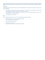
LD2103 V3.0 Page 1 of 33
SRT Marine
User Manual
Transas Class B Transponder
V1.0
LD2103 V3.0 Page 2 of 33
SRT Marine
Table of contents
Instruction
Table of contentsManual
............................................................................................................................................................................2
©
General Warnings .....................................................................................................................................................................4
SRT-MTB
Class B Marine AIS
FCC Compliance .......................................................................................................................................................................4
RF Emissions Notice ................................................................................................................................................................4
Product Specification ..................................................................................................................................................................6
Standards ...................................................................................................................................................................................6
Declaration of Conformity ...........................................................................................................................................................7
Introduction .....................................................................................................................................................................................8
How AIS Works...........................................................................................................................................................................8
AIS Classes ................................................................................................................................................................................8
Position Information Source........................................................................................................................................................8
Installing the TRANSAS AIS CLASS B- unit ...................................................................................................................................9
Electrical connections .................................................................................................................................................................9
Physical Mounting.....................................................................................................................................................................10
Programming the transponder ......................................................................................................................................................11
Programming the transponder ......................................................................................................................................................11
Programming software..............................................................................................................................................................11
Configuration ............................................................................................................................................................................11
Using the transponder ..................................................................................................................................................................12
Switching on .................................................................................................................................................................................12
Switch functions............................................................................................................................................................................12
Warning and fault states ...............................................................................................................................................................12
Data port messages..................................................................................................................................................................12
Information Transmitted and Received .....................................................................................................................................13
Built In Test...............................................................................................................................................................................13
LED Indicators ..........................................................................................................................................................................13
Maintenance .............................................................................................................................................................................15
Serial Data Interface .....................................................................................................................................................................16
Power Connection / Data Connection.......................................................................................................................................16
Serial Port Input/Output ............................................................................................................................................................16
Power up messages .................................................................................................................................................................17
VHF data link messages (NMEA 0183 VDM) ...........................................................................................................................17
VHF data link own vessel messages (NMEA 0183 VDO) .........................................................................................................18
Regional Assignment Channel Assignment Message (NMEA 0183 ACA)................................................................................18
Channel management information source messages (NMEA 0183 ACS)................................................................................19
AIS Alarm Messages (NMEA 0183 ALR, Text).........................................................................................................................19
ACK messages .........................................................................................................................................................................20
LD2103 V3.0 Page 3 of 33
SRT
Marine
Antenna connections
....................................................................................................................................................................21
GPS Antenna............................................................................................................................................................................21
VHF Antenna ............................................................................................................................................................................21
Instruction
Manual
©
Antenna types and mounting
....................................................................................................................................................21
SRT-MTB
Class
B Marine AIS
Drawings.......................................................................................................................................................................................22
Packing list................................................................................................................................................................................22
Glossary....................................................................................................................................................................................29
Appendix A ...................................................................................................................................................................................31
Antennas and Antenna Mounting..................................................................................................................................................31
GPS Antenna............................................................................................................................................................................31
VHF antenna for AIS use ..........................................................................................................................................................31
Warnings...................................................................................................................................................................................32
LD2103 V3.0 Page 4 of 33
SRT Marine
General Warnings
Instruction
Manual
All marine Automatic Identification System (AIS) units utilise a satellite based system such as the Global Positioning Satellite
© Navigation Satellite System (GLONASS) network to determine position.
(GPS) network or the Global
SRT-MTB
Class B Marine AIS
The accuracy of these networks is variable and is affected by factors such as the antenna positioning, how many satellites are
used to determine a position and how long satellite information has been received for.
It is desirable wherever possible therefore to verify both your vessels AIS derived position data and other vessels AIS derived
position data with visual or radar based observations.
The compass safe distance of this unit is 0.5m or greater for 0.3° deviation.
In accordance with a policy of continual development and product improvement the TRANSAS AIS CLASS B hardware and
software may be upgraded from time to time and future versions of the TRANSAS AIS CLASS B may therefore not correspond
exactly with this manual.
When necessary upgrades to the product will be accompanied by updates or addenda to this manual.
Please take time to read this manual carefully and to understand its contents fully so that you can install and operate your AIS
system correctly.
Information contained in this manual is liable to change without notice.
Transas Ltd. disclaims any liability for consequences arising from omissions or inaccuracies in this manual and any other
documentation provided with this product.
© 2007 Transas Ltd.
FCC Compliance
This equipment has been tested and found to comply with the limits for a Class B digital device, pursuant to part 15 of the
FCC Rules. These limits are designed to provide reasonable protection against harmful interference in a residential installation.
This equipment generates, uses and can radiate radio frequency energy and, if not installed and used in accordance with the
instructions, may cause harmful interference to radio communications. However, there is no guarantee that interference will not
occur in a particular installation. If this equipment does cause harmful interference to radio or television reception, which can be
determined by turning the equipment off and on, the user is encouraged to try to correct the interference by one or more of the
following measures:
Reorient or relocate the receiving antenna.
•
Increase the separation between the equipment and receiver.
•
Connect the equipment into an outlet on a circuit different from that to which the receiver is connected.
•
Consult the dealer or an experienced radio/TV technician for help.
•
The TRANSAS AIS CLASS B- does not contain any user serviceable parts. Repairs should only be made by an authorized
TRANSAS service agent. Unauthorised repairs or modifications could result in permanent damage to the equipment and void
your warranty and you’re authority to operate this equipment under Part 15 regulations.
RF Emissions Notice
Caution: The TRANSAS AIS CLASS B Class B AIS transponder generates and radiates radio frequency
electromagnetic energy. This equipment must be installed and operated according to the instructions contained in this
handbook. Failure to do so can result in personal injury and / or product malfunction.
Caution: Never operate the transponder unless it is connected to a VHF antenna.
To maximise performance and minimise human exposure to radio frequency electromagnetic energy you must make sure that
the antenna is mounted at least 1.5 meters away from the transponder and is connected to the transponder before power is
LD2103 V3.0 Page 5 of 33
SRT
applied. Marine
The system has a Maximum Permissible Exposure (MPE) radius of 1.5m. This has been determined assuming the maximum
Instruction
Manual
power of the transponder
and using antennas with a maximum gain of 3dBi.
©
SRT-MTB
Class
Ba greater
Marine
AIS
Higher gain antennas
will require
MPE radius.
•
•
The antenna should be mounted 3.5m above the deck in order to meet RF exposure requirements.
•
Do not operate the unit when anyone is within the MPE radius of the antenna (unless they are shielded from the
antenna field by a grounded metallic barrier).
The antenna should not be collocated of operated in conjunction with any other transmitting antenna.
•
This device has been designed to operate with standard marine VHF antennas having a maximum gain of 3dBi. Antennas not
included in this list or having a gain greater than 3dBi are strictly prohibited for use with this device. The required antenna
impedance is 50 ohms.
Licensing and Maritime Mobile Service Identity (MMSI)
IMPORTANT: In most countries the operation of an AIS unit is included under the vessel's marine VHF licence provisions. The
vessel on to which the AIS unit is to installed must therefore possess a current VHF radiotelephone licence which lists the AIS
system and the vessel Call Sign and MMSI number.
An MMSI number is required in order for the TRANSAS AIS CLASS B transponder to operate.
Please contact the relevant authority in your country for more information.
LD2103 V3.0 Page 6 of 33
SRT
Marine
Product
Specification
Parameter
Instruction Manual
Dimensions
©
Value
190 x 135 x 83 mm (L x W x H)
SRT-MTB
Class B1450g
Marine AIS
Weight
Power
DC (10.8 - 15.6V)
Average power consumption 4W
Peak current rating 2A
GPS Receiver (AIS Internal)
IEC 61108-1 compliant
Electrical Interfaces
RS232 38.4kBaud bi-directional
RS422 NMEA 38.4kBaud bi-directional
Connectors
VHF antenna connector
GPS antenna connector
RS232/RS422/Power
VHF Transceiver
Transmitter x 1
Receiver x 2 (One receiver time shared between AIS and DSC)
Frequency: 156.025 to 162.025 MHz in 25 kHz steps
Output Power
33dBm ± 1.5 dB
Channel Bandwidth
25kHz
Channel Step
25kHz
Modulation Modes
25kHz GMSK (AIS, TX and RX)
25kHz AFSK (DSC, RX only)
Bit rate
9600 b/s ± 50 ppm (GMSK)
1200 b/s ± 30 ppm (FSK)
RX Sensitivity
Sensitivity - 107dBm 25kHz (Message Error Rate 20%)
Co-channel 10dB
Adjacent channel 70dB
IMD 65dB
Blocking 84dB
Environmental
IEC 60945
Operating temperature: -25ºC to +55ºC
IEC 62287, Section 5, Cat (c) exposed to the weather
Indicators
Power, TX timeout, status, pre-set SRM sent.
Operator Controls
Optional pre-set safety related message (SRM) transmit button
Standards
This product complies to all the necessary standards under the European R&TTE directive for Article 3.1(a), 3.1(b), 3.2 and
3.3(e). The following standards have been followed in pursuance of this:
•
IEC62287-1: 2006-03 Maritime navigation and radiocommunication equipment and systems – Class B shipborne
equipment of the automatic identification system (AIS) – Part 1: Carrier-sense time division multiple access (CSTDMA)
LD2103 V3.0 Page 7 of 33
SRT techniques
Marine
•
IEC60945: 2002-08 Maritime navigation and radiocommunication equipment and systems – General requirements –
Methods of testing and required test results
Instruction Manual
©
SRT-MTB
Class
B Marine AIS
talker and multiple
listeners
•
IEC61162-1: Maritime navigation and radiocommunication equipment and systems – Digital interfaces – Part 1: Single
•
IEC61108-1: GLOBAL NAVIGATION SATELLITE SYSTEMS (GNSS) – Part 1: Global positioning system (GPS) Receiver equipment - Performance standards, methods of testing and required test results
•
EN 301 843-1 v2.1: Electromagnetic compatibility and Radio spectrum Matters (ERM); Electromagnetic Compatibility
(EMC) standard for marine radio equipment and services; Part 1: Common technical requirements
•
EN 50383: 2002 Basic standard for calculation and measurement of electromagnetic field strength and SAR related to
human exposure from radio base stations and fixed terminal stations for wireless telecommunications system (110MHz
– 40GHz)
•
EN60950-1:2002 Information technology equipment – Safety – Part 1: General requirements
Declaration of Conformity
Transas Ltd. declares that this product is in compliance with the essential requirements and other provisions of the R&TTE
directive 1995/5/EC.
The product carries the CE mark, notified body number and alert symbol as required by the R&TTE directive
The product is intended for sale in the following member states:
LD2103 V3.0 Page 8 of 33
SRT Marine
Introduction
Instruction Manual
How AIS Works
©
SRT-MTB
ClassSystem
B Marine
AIS
The marine Automatic Identification
(AIS) is a location
and vessel information reporting system. It allows vessels
equipped with AIS to automatically and dynamically share and regularly update their position, speed, course and other
information such as vessel identity with similarly equipped craft. Position is derived from a Global Navigation Satellite System
(GNSS) network and communication between vessels is by Very High Frequency (VHF) digital transmissions. A sophisticated
and automatic method of time sharing the radio channel is used to ensure that even where a large number of vessels are in one
location blocking of individual transmissions is minimised, any degradation of the expected position reporting interval is
indicated to the user and even if the unit suffers extreme channel overload conditions it will always recover to normal operation.
AIS Classes
There are two classes of AIS unit fitted to vessels, Class A and Class B. In addition AIS base stations may be employed by the
Coastguard, port authorities and other authorised bodies. AIS units acting as aids to navigation (A to Ns) can also be fitted to
fixed and floating navigation markers such as channel markers and buoys.
Class A units are a mandatory fit under the safety of life at sea (SOLAS) convention to vessels above 300 gross tons or which
carry more than 11 passengers in International waters. Many other commercial vessels and some leisure craft also fit Class A
units.
Class B units are currently not a mandatory fit but authorities in several parts of the world are considering this. Class B units are
designed for fitting in vessels which do not fall into the mandatory Class A fit category.
The TRANSAS AIS CLASS B - is a Class B unit
Position Information Source
As noted above the marine AIS system uses position information derived from networks such as the Global Positioning Satellite
(GPS) or the Global Navigation Satellite System (GLONASS) in order to determine the location of the AIS unit and thus the
vessel to which it is fitted.
The TRANSAS AIS CLASS B- utilises the GPS satellite network.
LD2103 V3.0 Page 9 of 33
SRT Marine
Installing the TRANSAS AIS CLASS B unit
Instruction
Manual
WARNING:
Do not connect the TRANSAS AIS CLASS B unit to a mains (line) AC electrical supply, as an electric shock or
©
fire hazard
could result.
SRT-MTB
Class
B Marine AIS
CAUTION:
Do not connect the TRANSAS AIS CLASS B unit to a DC supply exceeding 15.6 V or reverse the supply
polarity. Damage to the unit may result.
CAUTION:
The TRANSAS AIS CLASS B unit is designed for operation in the temperature range -25 °C to +55 °C. Do not
install (or use) the TRANSAS AIS CLASS B unit in environments which exceed this range.
CAUTION:
Do not install the TRANSAS AIS CLASS B unit in an environment where it can be subject to excessive
exposure to water.
Electrical connections
Warning: Only the RF, data and power cables provided with the TRANSAS AIS CLASS B unit should be used to connect
antennas, power and display devices so as to maintain the integrity of the enclosure.
Please see the drawings section of this manual for details of the power, data and RF cables supplied.
Remove the top of the transponder unit (eight screws) as shown.
Using the two co-axial leads supplied connect the down-lead from a VHF antenna to the VHF antenna port and connect the
down-lead of a GPS antenna to the GPS antenna port. Please see Appendix A for recommendations on antennas and antenna
installation.
If an external display unit (chart plotter, PC etc)
is to be used connect the supplied power and
data interface cable to the Power / NMEA port.
If an external display unit is not to be used
connect the supplied power only interface cable
to the Power / NMEA port.
Locate the RF, power and/or data cables into
the rubber grommets pushing them firmly to the
base of each slit. Each cable is pushed into the
grommet slit which lies directly in front of the
connector the cable is connected to.
Replace the top of the transponder unit taking
care to seat the cable grommets and the lid
seal correctly. Do not over-tighten the fixing
screws.
GPS Antenna Cable
VHF Antenna Cable
If an external display unit is to be used (such as
a chart plotter, PC serial terminal or other
display device) connect the user end of the
data interface cable to the display device. Note
that the software in the display device must be
configured for AIS operation AND to accept
standard Class B operation NMEA sentences.
This external display unit software is not part of
the TRANSAS AIS CLASS B transponder
package.
Connect a 12V DC supply (9.6-15.6V) capable
of supplying 2A peak to the DC power lead
(brown/red = positive, black/blue=negative).
Power Cable (or Power and Data Cable)
The case of the unit is not isolated from the negative terminal of the supply and therefore it is recommended that the
LD2103 V3.0 Page 10 of 33
SRT
unit is notMarine
attached to metal parts of the vessel.
Instruction
Manual
Physical Mounting
©
It is recommended that the
unit is attached
a solid wooden surface
SRT-MTB
Class
Bto Marine
AISwith 20mm M3 self tapping screws. A template for drilling
pilot holes is shown on page 23.
LD2103 V3.0 Page 11 of 33
SRT Marine
Programming the transponder
Instruction Manual
Programming software
©
SRT-MTB
Marine
AIS
Before the TRANSAS AISClass
CLASS B can B
be used
it requires ‘personalisation’.
This is done via the TRANSAS AIS CLASS B proAIS package which is supplied as an accessory. The proAIS user guide
contains more detail on configuration of the transponder.
This software is designed to be installed on a PC and to use the data lead provided as standard with the TRANSAS AIS CLASS
B unit. If the PC being used for programming does not have a 9-pin serial port then a commercially available USB to serial
adaptor may be required. This connects between the supplied data lead and the PC.
Configuration
The TRANSAS AIS CLASS B personalisation data required is the ship’s MMSI, the ship’s name, its dimensions, position
reference, type and call sign. Please refer to the proAIS user guide for more information on configuration and installation
diagnostics.
LD2103 V3.0 Page 12 of 33
SRT Marine
Using the transponder
Instruction Manual
Switching on
©
SRT-MTB
Class B Marine AIS
When the 12V supply is switched on all four LEDs visible on the front panel of the unit will illuminate twice for a period of one
second on each illumination. The red and blue LEDs will then go out. When the internal GPS starts outputting valid position
information and the TRANSAS AIS CLASS B unit transmits its first position report (message 18) the yellow LED will go out;
note that this process may take up to 30 minutes depending on the switch-on state of the GPS receiver. When the yellow LED
goes out the green LED will illuminate indicating that the unit is now operating correctly.
Switch functions
S
The blue switch on the front of the unit can be configured either to
trigger transmission of a "Safety Related Message" or to place the unit
into "Silent mode". This choice is made during configuration of the unit
using the proAIS application; please refer to the proAIS user guide for
further information on the configuration options.
When configured to transmit a "Safety Related Message" the button
will initiate broadcast of an AIS message containing the vessels MMSI
along with the text "MAYDAY MAYDAY". The button must be pressed
for at least two seconds to initiate this transmission and the blue LED
will illuminate to indicate the message has been sent. Additional
"Safety Related Messages" can not be sent until the blue LED has
extinguished which will occur one minute after an SRM has been sent.
Green (Unit operating OK)
Yellow (Warning)
Red (Fault)
Blue
(Status)
When configured to place the unit into "Silent mode" each press of the switch will toggle the AIS transmitter on or off. The switch
must be depressed for two seconds to change the state of the transmitter. When the transmitter is off, the yellow "Warning" LED
and blue "Status" LEDs will be illuminated and the transponders position will not be broadcast to other vessels. The position of
other vessels will still be received by the unit.
Warning and fault states
If the unit has not been able to transmit a position report during the last expected two reporting intervals (i.e. the nominal
reporting interval cannot be maintained for operational reasons such as a Message 23 quiet period, high channel load
conditions, etc) the yellow LED will illuminate. This is a warning condition only and indicates that your vessels position is not
currently being reported to other vessels. Reception of other vessel AIS information by the TRANSAS AIS CLASS B is not
affected. When the unit is able to commence reporting the yellow LED goes out.
If a fault occurs the red LED will illuminate. This may illuminate briefly if the power supply is interrupted or if the VHF antenna
characteristics are briefly affected.
If the Red LED illuminates continuously the unit should be assumed to be faulty and should either be switched off (power
removed) or if this is not practical any other vessel position information derived from the unit should not be used and it should
also be assumed that the unit is not transmitting valid position information for your vessel.
The unit should be examined by a competent equipment maintainer at the earliest opportunity.
Data port messages
The data port will output the following:
•
(At power-up) boot-loader and main application splash text screens including version numbers, and memory status
LD2103 V3.0 Page 13 of 33
SRT
Marine
Details
of relevant AIS transmissions received
•
•
Details of AIS transmissions sent
Instruction
Manual
Details of
channel management messages received
•
©
Alarm messages generated by the BIIT function
•
SRT-MTB
Class B Marine AIS
The data port will accept the following inputs:
•
Programming information
•
Alarm acknowledgements
Please see the ‘Data Interface’ section of this manual for more details of the data port messages.
When in operation an AIS unit:
•
Uses one of two VHF channels within the international marine band allocation (channel 87B; 161.975MHz, or channel
88B; 162.025MHz) to regularly transmit information such as the vessel position, Maritime Mobile Service Identity
(MMSI), name, speed, course, etc.
•
Receives similar information from other AIS equipped vessels within VHF range and outputs that information for use by
an external display medium (AIS enabled chart plotter, PC using AIS enabled chart plotter software etc.)
Information Transmitted and Received
A Class A unit will transmit its IMO number (if known), MMSI, Call sign and Name, length and beam, ship type, time, course
over ground (COG), speed over ground (SOG), heading, navigational status, rate of turn, draught, cargo type, destination and
safety related messages via a short message service (SMS) facility. Message lengths are variable with static and voyage
related information being transmitted less often.
A Class B unit will transmit its MMSI, Call Sign and Name, length and beam, ship type, time, course over ground (COG), speed
over ground (SOG) and heading.
Built In Test
The TRANSAS AIS CLASS B- unit is equipped with Built In Integrity Testing (BIIT). BIIT tests run continuously or at appropriate
intervals simultaneously with the standard functions of the equipment. The BIIT detects any failure or malfunction that will
significantly reduce integrity or stop operation of the TRANSAS AIS CLASS B- unit.
The tests include:
•
AIS TX malfunction (synthesiser not locked and TX time-out not exceeded)
•
Antenna VSWR exceeds limit
•
Rx channel 1 malfunction (synthesiser not locked)
•
Rx channel 2 malfunction (synthesiser not locked)
•
Internal GNSS not in use
•
No valid SOG information
•
No valid COG information
•
Background noise > -77dBm
•
GPS failure
•
VSWR exceeding the maximum allowed level
•
The input voltage is out of the specified range
LED Indicators
Power
LD2103 V3.0 Page 14 of 33
SRT
Marine
This is a green
LED which indicates, when lit, that power has been connected correctly to the transponder, that the transponder
hardware has been configured, that the operating software is present, that the CPU has booted up, the application software is
running.
Instruction
Manual
TX Timeout
©
SRT-MTB
Class
B litMarine
AIS
This is a yellow LED which
indicates when
that the CSTDMA
transmitter is prevented from transmitting.
Reasons for this
include the following:
•
The transponder’s internal GPS receiver is not operating or is not yet ready. [1] requires that a class B CSTMA
transponder shall not transmit if its internal position sensor is not operating
•
The transponder was unable to transmit an AIS message due to the channel being already occupied, e.g. by
transmissions from other AIS transponders
•
The transponder is in "Silent mode"
Error
This is a red LED which indicates, when lit, one of the following status conditions is possible:
•
Transmitter lockout timer (1 second maximum) has operated
•
GPS is unable to gain lock after 30 minutes
•
VHF antenna VSWR is out of range
•
Power supply is out of range
•
Background noise level is above the threshold level (-77dBm)
LD2103 V3.0 Page 15 of 33
SRT
Marine
Status
This is a blue LED which either indicates that a Safety Related Message has been transmitted or that the unit is in "Silent
mode". The condition indicated by the blue LED is determined during configuration of the unit by the switch option selected.
Instruction
Manual
Please refer to the "Switch functions" section of this manual for more detail.
©
SRT-MTB
Class B Marine AIS
Transmission of a Safety Related Message is indicated by both the green and blue LEDs being illuminated
•
POWER
•
TIMEOUT
ERROR
STATUS
Silent mode is indicated by both the yellow and blue LEDs being illuminated.
POWER
TIMEOUT
ERROR
STATUS
Antennas
The TRANSAS AIS CLASS B - unit requires VHF and GPS antennae independent from those in use for other purposes. Please
see Appendix A for details of the antennae required.
Maintenance
WARNING:
Unauthorised opening of the TRANSAS AIS CLASS B system will invalidate the warranty.
CAUTION:
material.
Avoid using chemical solvents to clean the TRANSAS AIS CLASS B as some solvents can damage the case
NOTE:
The TRANSAS AIS CLASS B contains no user serviceable parts. Contact your Service Agent for repair if
replacing the fuse fails to make the equipment serviceable.
LD2103 V3.0 Page 16 of 33
SRT Marine
Serial Data Interface
Instruction Manual
Power Connection / Data Connection
©
SRT-MTB
Bmounted
Marine
There is a 15-way D-typeClass
male connector
under theAIS
transponder top cover.
The standard data or power and data
cable assembly provided mates with this connector.
Power
12V DC (9.6-15.6V) is connected to the transponder power supply input via the cable assembly LD1873.
Data
A minimum keypad and display (MKD) unit, chart plotter or other display device may be connected to the TRANSAS AIS
CLASS B unit via the appropriate cable assembly. The default baud rate of the data link is 38.4kBaud with 8 data bits, one stop
bit and no parity. No handshaking is used.
The data interface conforms to IEC 61162-1.
VDM, VDO, ACA, ACS, ALR, TXT and ACK messages conform to NMEA 0183. Please refer to NMEA 0183 for full details of
these AIS messages.
Serial Port Input/Output
There are two serial ports, one presenting RS422 format and the other RS232 format. Data can be input from either or both
ports.
The serial port interface(s) output:
•
At power-up boot-loader and main application splash text screens including version numbers and memory status.
•
As a VHF Data Link Message (VDM) all incoming VHF Data Link (VDL) data received by the TRANSAS AIS CLASS B.
•
The VHF data link own vessel (VDO) messages sent by the TRANSAS AIS CLASS B over the VHF Data Link.
•
AIS regional channel assignment messages (ACA) received. These are derived from an incoming VHF Data Link
message (message 22) or a DSC message.
•
AIS channel management information source (ACS) messages.
•
Alarm messages (ALR, TXT).
The data interface will accept:
•
Personality programming messages
•
Alarm acknowledgement messages (ACK)
LD2103 V3.0 Page 17 of 33
SRT
Power Marine
up messages
On power up the unit will report details of the firmware versions residing in the unit.
Instruction Manual
©
VHF data link messages
0183 VDM)
SRT-MTB
Class(NMEA
B Marine
AIS
Receipt of a VHF Data Link (VDL) message on either AIS radio channel causes a VDM message to be output via the data port.
Please see IEC 61193-2, Annex B for a list of messages.
VDM Message Format
!--VDM,x1,x2,x3,a,s--s,x*hh<CR><LF>
Where:
•
x1 = Total number of sentences needed to transfer the message , 1 to 9
•
x2 = Sentence number, 1 to 9
•
x3 = Sequential message identifier, 0 to 9
•
a = AIS Channel, "A" or "B"
•
s - - s = Encapsulated ITU-R M.1371 radio message
•
x = Number of fill-bits , 0 to 5
VDM Message Types
For example, the information contained in the s - - s portion of the VDM = Encapsulated ITU-R M.1371 radio message. Note
that messages 5 and 19 may be sent as multi part messages using the x1, x2 and x3 parameters for message sequence
control.
VDL Message number
VDM Message description
AIS Target Display Information
1, 2, 3, 9,18, 21
position report
4
base station report
5*
voyage related data
19*
Class B – extended data
Safety message handling
12
addressed safety related
14
broadcast safety related
External Application handling
6
binary addressed
8
binary broadcast
System control
7
binary acknowledge (INFO)
10
UTC and data inquiry (INFO)
11
UTC and data response (INFO)
13
safety related ack (INFO)
15
interrogation (INFO)
16
assignment mode command (INFO)
LD2103 V3.0 Page 18 of 33
SRT
Marine
VDL Message number
VDM Message description
17
DGNSS corrections (INFO)
Instruction Manual
20
©
data link management (INFO)
SRT-MTB
Classchannel
B Marine
AIS
22
management (INFO)
*Note that messages 5 and 19 may be sent as multi part messages.
VHF data link own vessel messages (NMEA 0183 VDO)
This message describes the own vessel message being sent.
VDO Message Format
!--VDO,x1,x2,x3,a,s--s,x*hh<CR><LF>
Where
•
x1 = Total number of sentences needed to transfer the message , 1 to 9
•
x2 = Sentence number, 1 to 9
•
x3 = Sequential message identifier, 0 to 9
•
a = AIS Channel, "A" or "B"
•
s - - s = Encapsulated ITU-R M.1371 radio message 4
•
x = Number of fill-bits , 0 to 5
VDO Message number
VDO Message description
AIS Target Display Information
13
Safety Related Acknowledgement
18
Standard Class B position report (Includes MMSI, SOG, position accuracy, lat, long,
COG, true heading,)
24a
Class B “CS” Static data Part A (Includes MMSI and vessel name)
24b
Class B “CS” Static data Part B (MMSI, ship type, cargo type, call sign, ship dimensions)
Regional Assignment Channel Assignment Message (NMEA 0183 ACA)
An TRANSAS AIS CLASS B unit can receive regional channel management information in two ways: ITU-R M.1371 message
22 or a DSC telecommand received on channel 70,
ACA Message Format
$--ACA,x,llll.ll,a,yyyyy.yy,a,llll.ll,a1,y1y1y1y1y.y1y1,a2,x1,x2x2x2x2,x3,x4x4x4x4,x5,x6,x7,a3,x8,hhmmss.ss*hh
<CR><LF>
Where
•
x = Sequence Number , 0 to 9
•
IIII, II, a = Region Northeast corner latitude – N/S
•
yyyyy.yy,a1 = Region Northeast corner longitude – E/W
•
llll.ll,a = Region Southwest corner latitude – N/S
•
y1y1y1y1y1.y1y1,a2 = Region Southwest corner longitude – E/W
•
x1 = Transition Zone Size
•
x2x2x2x2 = Channel A
LD2103 V3.0 Page 19 of 33
SRT
Marine
x3
= Channel A bandwidth
•
•
x4x4x4x4 = Channel B
Instruction
Manual
x5 = Channel
B bandwidth
•
©
x6 = Tx/Rx mode control
•
SRT-MTB
Class B Marine AIS
•
x7 = Power level control
•
a3 = Information source
•
x8 = In-Use Flag
•
hhmmss.ss = Time of "in-use" change
Channel management information source messages (NMEA 0183 ACS)
This sentence is used in conjunction with the ACA sentence and identifies the originator of an ACA message.
ACS Message Format
$--ACS,x,xxxxxxxxx, hhmmss.ss,xx,xx,xxxx*hh <CR><LF>
•
x = Sequence Number , 0 to 9
•
xxxxxxxxx =MMSI of originator
•
hhmmss.ss = UTC of receipt of channel management information
•
xx = UTC Day, 01 -31
•
xx = UTC Month, 01 -12
•
xxxx = UTC Year
AIS Alarm Messages (NMEA 0183 ALR, Text)
ALR message format
$--ALR,hhmmss.ss,xxx,A,A,c--c*hh<CR><LF>
Where
•
hhmmss.ss = Time of alarm (UTC)
•
xxx = Unique alarm number
•
A = Alarm condition
•
A = Alarm acknowledge state
•
c--c = alarm description, text
Alarms descriptions presented are:
•
AIS: TX malfunction
•
AIS: Antenna VSWR exceeds limit
•
AIS: Rx channel 1 malfunction
•
AIS: Rx channel 2 malfunction
•
AIS: general failure
•
AIS: no sensor position in use
•
AIS: no valid SOG information
•
AIS: no valid COG information
LD2103 V3.0 Page 20 of 33
SRT
Marine
AIS:
12V alarm
•
•
AIS: 5V alarm
Instruction
Manual
AIS: Loss
of serial interface integrity
•
©
AIS: Background noise above -77dBm
•
SRT-MTB
Class B Marine AIS
ACK messages
Can be generated by a minimum keypad and display (MKD) unit, chart plotter or other display device connected to the
TRANSAS AIS CLASS B to acknowledge an alarm condition reported by the TRANSAS AIS CLASS B.
ACK message format
$--ACK,xxx*hh <CR><LF>
Where
•
xxx = unique alarm number
LD2103 V3.0 Page 21 of 33
SRT Marine
Antenna connections
Instruction Manual
GPS Antenna
©
SRT-MTB
Class
Bmounted
Marine
This is a TNC female bulkhead
connector
under the AIS
unit top cover.
GPS antenna required by the TRANSAS AIS CLASS B unit.
VHF Antenna
This is a BNC female bulkhead connector mounted under the unit top cover.
Antenna types and mounting
Please see Appendix A for antenna details.
This port provides the 5V DC feed for the active
LD2103 V3.0 Page 22 of 33
SRT Marine
Drawings
Instruction Manual
Packing list
SRT-MTB© Class B Marine AIS
REVISION HISTORY
REV
1
2
DESCRIPTION
DATE
PRODUCTION RELEASE
MAGNET PACK REMOVED
APPROVED
23/2/06
15/6/06
THIRD ANGLE PROJECTION
7
5
8
9
10
2
1
3
ITEM
5
DESCRIPTION
QTY
LD2095
AIS CLASS B TRANSPONDER UNIT
2
NA
POLYTHENE BAG 300 x 300 mm
1
3
NA
SILICA GEL SACHET
1
4
11
SRT PARTNo.
1
LD2098
OUTER PACKING CARTON
5
LD2099
INNER PACKING (2 ITEMS)
6
NA
CARTON IDENTIFICATION LABEL
7
LD2103
INSTRUCTION MANUAL
8
LD2104
INSTALLATION TEMPLATE
1
1
1
1
1
1
9
LD2110
INSTALLATION DIAGRAM
10
LD2111
UNIT DIMENSIONS DRAWING
11
LD2121
POWER CABLE ASSEMBLY, KIT 3 (0.5m LONG)
1
12
LD2134
MOUNTING SCREW KIT
1
1
1
NA = NOT APPLICABLE
MATERIAL
REFER TO LIST
4
NAME
DRAWN
FINISH
12
6
SOFTWARE RADIO TECHNOLOGY PLC
COPYRIGHT
THIS DRAWING IS NOTTO BE REPRODUCED
WITHOUTWRITTEN PERMISSION FROM SRTPLC.
DATE
M. KENDALL 06/15/06
WESTFIELD INDUSTRIAL ESTATE
MIDSOMER NORTON, BATH, UK.
BA3 4BS
TITLE
CHECKED
AIS CLASS B TRANSPONDER
PACKED ASSEMBLY
UNLESSOTHERWISE SPECIFIED
SIZE DWG NO
DIMENSIONS ARE IN MILLIMETERS
ANGLES ± 0.5°
FILE NAME: LD2114-2.dft
0.0 ± 0.2 0.00 ± 0.1
REV
2
A1
SCALE:
SHEET1 OF 1
LD2103 V3.0 Page 23 of 33
SRT
Fixing Marine
Template (NOT TO SCALE)
Instruction Manual
SRT-MTB© Class B Marine AIS
REVISION HISTORY
REV
DESCRIPTION
DATE
APPROVED
MOUNTING HOLES IN BASE PLATE
ARE O5.5 TO SUITM5 SCREWS
100,0
MOUNTING HOLE
FIXING CENTRES
TEMPLATE
FRONTOF UNIT
160,0
NAME
DATE
M.KENDALL 24/2/06
DRAWN
CHECKED
SOFTWARE RADIO TECHNOLOGY PLC
WESTFIELD INDUSTRIAL ESTATE
MIDSOMER NORTON, BATH, UK. BA3 4BS
TITLE
AIS CLASS B TRANSPONDER
INSTALLATION TEMPLATE
SIZE DWG NO
LD2104
REV
UNLESS OTHERWISE SPECIFIED
A4
2
DIMENSIONS ARE IN MILLIMETERS
FILE NAME: LD2104-2.dft
ANGLES ± 0.5°
0.0 ± 0.2 0.00 ± 0.1
SCALE: 1:1
SHEET1 OF 1
LD2103 V3.0 Page 24 of 33
SRT Marine
General arrangement
Instruction Manual
SRT-MTB© Class B Marine AIS
REVISIO N HISTO RY
REV
1
2
DESCRIPTION
DATE
PRODUCT ION RELEASE
BUTTO NC HANG ED TO M EM BRANESWITC H
APPRO VED
2 3/0 2/06
15/6/0 6
TH IRD AN GLE PRO JEC T
IO N
17 5,0
4H OLES
O 5 ,5
13 5,0
10 0,0
16 0,0
R 8,0
90 ,7
7 ,5
M ATERIAL
2, 0
16 0,0
19 0,0
30 ,0
1 5 ,0
20 ,0
COP
Y IRGH T
SOFTWARE RADIO TECHNO LOGY PLC
T
H IS DRAWIN G IS NOT T
O BEREPRO DUC ED
RUBBERSHEET
WITHO UTWRITTENPE RMI SSIO NFRO M SRT PL
C . WESTFI
ELD INDUSTRIAL ESTATE
1m m THICK
MIDSOMERNORTON, BATH, UK.
G RADE TO BE DECIDED.
NAME
DATE
DRAWN
FIN ISH
CHECKED
M . KENDA LL 0 6/1 5 /0 6
BA3 4BS
TITLE
AIS CLASS B TRANSPONDER
UNITDIMENSIO NS
UNLE
S SOTHERWISESPECIF IED SIZE DWG NO
DIMENSIONSAREINM ILLIMETERS
ANGLES± 0.5 °
F
I LE N AME: LD 21 11 - 2.d
ft
0. 0 ± 0.2 0 .0 0± 0.1
S
C AL E
1: :1
A1
REV
LD 2111
2
SHEET 1 OF 1
LD2103 V3.0 Page 25 of 33
SRT Marine
Mechanical Breakdown
Instruction Manual
SRT-MTB© Class B Marine AIS
REVI SION HISTORY
DESCRIPTIO N
DAT E
1
THIRD ANGLE PROJEC TION
12
8
8
7
14
8
2
3
20
18
4
19
(COMPONENTS NOT SHOWN)
24
REFER TO NOTE
16
6
REFER TO NOTE
17
6
NA = NO T APPLICABLE
15
6
25
5
THIS DRAWING SHOWS TWO BUILD VARIANTS.
1. FITTED WITH MEMBRANE ALERT SWITCH PANEL - USE ITEM 24.
2. NO ALERT SWITCH FITTED - USE ITEM 25.
6
14
6
MATERIAL
COPYRIGHT
13
NAME
6
DRAWN
FINISH
DATE
06/15/ 06
CHECKED
BA3 4BS
TITLE
AIS CLASS 'B' TRANSPONDER
GENERAL ASSEMBLY
SIZE DWG NO
ANG LE S ±0.5°
0.0 ±0.2 0.00 ±0.1
LD 2007
FILE NAME: LD2007-4.df t
SCALE: 0.85:1
SHEET1 OF 2
REV
4
LD2103 V3.0 Page 26 of 33
SRT Marine
Cable Assemblies
Instruction Manual
SRT-MTB© Class B Marine AIS
POWER CABLE ASSEMBLY
LD 2109
LD2103 V3.0 Page 27 of 33
SRT Marine
Instruction Manual
SRT-MTB© Class B Marine AIS
CLAS S B TRANSP O NDER
VHF E XTERNA L CABLE
LD 2131
LD2103 V3.0 Page 28 of 33
SRT Marine
Instruction Manual
SRT-MTB© Class B Marine AIS
/BLACK
/RED
POWER AND DATA
CABLE ASSEMBLY
LD 2122
LD2103 V3.0 Page 29 of 33
SRT Marine
Glossary
ACA
(AIS) Regional Assignment Channel Assignment Message
Instruction
Manual
©
ACK
Acknowledgement
SRT-MTB
Class B Marine AIS
ACS
(AIS) Channel management information source messages
AFSK
Audio frequency-shift keying
ALR
(AIS) Alarm Message
A to N
Aid to Navigation
AIS
Automatic Identification System
BIIT
Built In Integrity Testing
BNC
Bayonet fitting type RF connector
CSTDMA
Carrier Sense Time Division Multiple Access
COG
Course over Ground
CR
Carriage Return
CS
Carrier Sense
CSTDMA
Carrier Sense TDMA
DC
Direct Current
DGNSS
Differential Global Navigation Satellite System
DSC
Digital Selective calling
GLONASS
Global Navigation Satellite System
GNSS
Global Navigation Satellite System
GMSK
Gaussian Minimum Shift Keying
GPS
Global Positioning Satellite / System
HF
High Frequency
IMO
International Maritime Organization
IEC
International Electrotechnical Commission
LED
Light Emitting Diode
LF
Line Feed
LNA
Low-noise amplifier
MF
Medium Frequency
MKD
Minimum Keypad and Display
MMSI
Maritime Mobile Service Identity
MPE
Maximum Permissible Exposure
NMEA
National Marine Electronics Association
PC
Personal Computer
PI
Presentation Interface
RF
Radio Frequency
RTCM
Radio Technical Commission for Maritime Services Commission
RX
Receive or Receiver
LD2103 V3.0 Page 30 of 33
SRT
Marine
RFI
Radio frequency interference
SAR
Specific Absorption Rate
SMS
Short Message System
Instruction
Manual
© over Ground
SOG
Speed
SRT-MTB
Class B Marine AIS
SRM
Safety Related Message
TDMA
Time-division Multiple Access
TNC
Threaded type BNC connector
TX
Transmit or transmitter
UTC
Universal Time Co-ordinated
VDM
(AIS) VHF Data Link Messages
VDO
(AIS) VHF data link own vessel messages
VHF
Very High Frequency
VSWR
Voltage Standing Wave Ratio
LD2103 V3.0 Page 31 of 33
SRT Marine
Appendix A
Instruction Manual
©
Antennas
and BAntenna
Mounting
SRT-MTB
Class
Marine AIS
GPS Antenna
The GPS antenna used must be of the active type (i.e. it should incorporate an LNA) and must be suitable for marine shipboard
applications (index of protection, ruggedness, means of mounting, etc.). An antenna should be selected with a gain (in dB)
depending on the length of cable between the antenna and the AIS unit; after subtraction of cable and connector losses a
minimum total gain of 25 dB should be available at the TRANSAS AIS CLASS B unit GPS antenna connector.
The GPS antenna to be used for AIS use must be a dedicated antenna, i.e. not shared with any other GPS receiver.
Installation of the GPS antenna is critical for the performance of the built in GPS receiver which is used for timing of the
transmitted time slots and for the supply of navigational information should the main navigational GPS fail. We strongly
recommend that:
•
The GPS antenna is mounted in an elevated position and free of shadow effect from the ship’s superstructure
•
The GPS antenna has a free view through 360 degrees with a vertical angle of 5 to 90 degrees above the horizon.
•
As the received GPS signal is very sensitive to noise and interference generated by other onboard transmitters, ensure
that the GNSS antenna is placed as far away as possible from radar, Inmarsat and Iridium transmitters and ensure the
GPS antenna is free from direct view of the radar and the Inmarsat beam.
•
It is also important that the MF/HF and other VHF transmitter antennas are kept as far away as possible from the
GNSS antenna. It is good practice never to install a GNSS antenna within a radius of 5 meters from these antennas.
VHF antenna for AIS use
The VHF antenna employed for AIS use:
•
Must be a dedicated antenna, i.e. not shared with any other VHF transmitter/receiver.
•
Must be suitable for marine shipboard applications (index of protection, ruggedness, means of mounting, etc.)
•
Should be omni-directional and vertically polarised with maximum gain of 3dBi and bandwidth sufficient to maintain
VSWR <1.5 over the frequency range 156 – 163 MHz. As a minimum the 3dB bandwidth must cover the two AIS
channels and the DSC Channel.
•
Should be mounted with at least a two metre vertical separation distance from any other VHF antenna used for speech
or DCS communication but see also the section “Radio Frequency Exposure Warning” below.
LD2103 V3.0 Page 32 of 33
SRT
Marine
Warnings
VHF Antenna Connection
Instruction
Manual
Connecting a badly mismatched VHF antenna, leaving the VHF antenna port disconnected, or shorting the VHF antenna port
will activate the VSWR©alarm, cause the unit to stop sending position reports or cause damage to the transponder.
SRT-MTB
Class B Marine AIS
Radio Frequency Exposure
To meet the requirements for Radio Frequency Exposure it is necessary to install the VHF antenna correctly and operate the
AIS equipment according to the instructions.
LD2103 V3.0 Page 33 of 33
SRT Marine
Instruction Manual
SRT-MTB© Class B Marine AIS