1
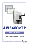
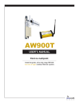
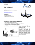
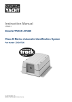
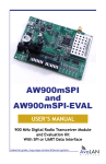
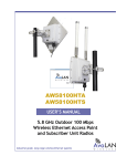
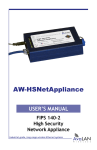
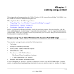
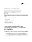
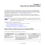
AW2400R2-PAIR
User’s Manual
2.4 GHz Outdoor Wireless RS-232 Bridge
Industrial-grade, long-range wireless systems
AvaLAN
W
I
R
E
L
E
S
S
AW2400R2-PAIR User’s Manual
Thank you for your purchase of the AW2400R2-PAIR Outdoor Wireless RS-232 Bridge.
If you have any questions when configuring your AvaLAN system, the best place to
get answers is to visit www.avalanwireless.com. You will also find the latest updates
there.
If more assistance is needed, send email to [email protected].
To speak to a live technician, please call technical support at the number below
during normal business hours.
Limited Warranty
This product is warranted to the original purchaser for normal use for a period of 360 days
from the date of purchase. If a defect covered under this warranty occurs, AvaLAN will repair
or replace the defective part, at its option, at no cost. This warranty does not cover defects
resulting from misuse or modification of the product.
© by AvaLAN Wireless Systems Inc. All rights reserved.
Revision 04.10.2013
125A Castle Drive
Madison, AL 35758
Sales: (866) 533-6216
Technical Support: (650) 384-0000
Customer Service: (650) 641-3011
Fax: (650) 249-3591
Technical support (650) 384-0000
PAGE 2
www.avalanwireless.com
User’s Manual AW2400R2-PAIR
Operational summary
RS-232 is a point-to-point serial data connection that requires just three wires:
Transmit Data, Receive Data and Ground. Because there is no handshake involved,
both ends must be configured for matching data timing and protocol or communication will not occur. Also, it is possible to lose data if the receiving device cannot
keep up with the sending device. The AW2400R2-PAIR supports data rates from 9600
Baud to 115,200 Baud and has a 4 KB data buffer. When properly configured, this
pair of radios behave just like an RS-232 cable but without the length constraint and
without a physical wire.
The AW2400R2-PAIR is shipped from the factory pre-configured to meet most user’s
needs. If this configuration works for you, most of the rest of the information in this
manual is not relevant. The pre-configuration settings are:
• One radio is the Access Point or master and the other radio is the Subscriber
Unit or client.
• The RF frequency channel will automatically change to avoid interference.
• The Network ID and AES Encryption Key are all zeros.
• The serial port settings are 115200 Baud, 8 data bits, 2 stop bits, no parity.
• Tuning parameters are optimized for minimum latency: Next Byte Delay - 00,
Minimum Packet Size - 01, Maximum Packet Size - 024. These parameters are
explained on page 7.
AW2400R2 radios may be re-configured by removing the cover and connecting a PC
to a USB port on the module inside. A utility program from AvaLAN is then run on
the PC that can set the configuration and check the link status. The LED display on
the inside module is also a very useful indicator of the condition of the wireless
connection.
The access point (AP) automatically scans for the best of the 29 available radio
frequency channels, encrypts RS-232 data received, and transmits it wirelessly to
the subscriber unit (SU). The AP is constantly monitoring the radio link and can
automatically change the channel if performance is degraded due to interference.
If two AP units from two different bridges are very close to one another, they may
interfere if operating on adjacent frequency channels. Place them at least 10 feet
apart or manually select non-adjacent channels for their operation. Also, the two
radios in the bridge should be placed at least 10 feet apart to avoid overloading the
radio receivers.
At each end of the wireless bridge, the RS-232 device wired to the AW2400R2-PAIR
must have its transmit signal connected to the radio’s receive and vice versa. Miswiring will not cause damage, but will prevent communication.
Technical support (650) 384-0000
PAGE 3
www.avalanwireless.com
AW2400R2-PAIR User’s Manual
Electrical Connections
The AW2400R2-PAIR 2.4 GHz Outdoor Wireless RS-232 Bridge contains two each of
the following items:
• Outdoor wireless RS-232 radios
• AW2-2400 Omnidirectional Antennas
• RJ-45 to Screw Terminal 30 foot cables
• DB-9 Female to Screw Terminal breakout adapters
• 20” USB to Mini-USB Adapter Cables
• 120VAC to 12 VDC Wall Hanger Power Supplies
Antennas or other useful accessories such as pole-mounting brackets may be purchased from AvaLAN Wireless or our distributors.
To power up a radio, make connections to it as shown in this diagram:
Terminal Block
RS-232
Data
Source
Receive
Rx (orange twisted pair)
Transmit
Tx (green twisted pair)
Ground
GND (brown twisted pair)
+ (blue twisted pair)
White-striped
wire: +12 VDC
Plain black
wire
30’ Cable
Screw Terminals
to RJ-45
2.4 GHz
Antenna
12 VDC Power Supply
Weatherproof
Sealing Gland
Connect both ends of the wireless link to their respective RS-232 devices, power
supplies and antennas in similar fashion. The radios use an RJ-45 connector for
data because they leverage the weatherproof solution already developed for our
Ethernet products. If the length or termination method of the cable supplied does
not meet your needs, an inexpensive CAT5 cable can be used by installing an RJ-45
plug on the radio end and terminating the other end however you wish.
Provide some physical separation between two radio module antennas — at least
ten feet. If their antennas are in close proximity, the module radio receivers will be
overloaded, causing degradation in the bit error rate and slower link performance.
Technical support (650) 384-0000
PAGE 4
www.avalanwireless.com
User’s Manual AW2400R2-PAIR
Configuration
Setting or changing the configuration (Baud rate, etc.) of the AW2400R2-PAIR is done
via the USB interface on their internal modules. Follow these steps with both radios:
1. Remove the four screws holding the radio’s cover. The screws have a 1/8” Allen
hex head. Be careful not to damage the rubber sealing gasket or the lip on the box.
A labeled picture of the internal module may be found on page 10.
2. The PC that you will connect via USB to the module must have a USB 2.0 or later
port available and be running MS Windows XP or later. In addition, three critical
pieces of software must be installed; a driver, a utility and a dll.
3. Your PC requires a virtual COM port driver to allow communication with the USB
interface chip in the module. This driver may be downloaded from the chip manufacturer’s website, http://www.ftdichip.com. On their site menu, select “Drivers”
and “VCP” (Virtual COM Port). Next, choose the driver corresponding to your PC’s
operating system and our chip, which is an FT232R. We tested Driver Version
2.06.02, dated 31 March 2010. Download the zip file from their site. You would also
be advised to download the installation guide for your operating system, available
from the link at the top of the driver selection page. Extract the driver zip file to a
folder of your choice, connect the module to your PC using the supplied USB cable
and follow the instructions in the installation guide. Once you are successful, you
should be able to open Windows Device Manager and see something like this in the
“Ports” section:
The device labeled “USB Serial Port (COM6) is the connection to the radio module.
Windows chooses which COM port number to assign, so yours is unlikely to be COM6.
In fact, every time you plug and unplug the USB or restart your computer, the assigned COM port number will probably be different.
4. Next, you will need a configuration utility and its associated dll file from AvaLAN.
Go to our website, http://www.avalanwireless.com. Navigate to “Support” then
“Downloads.” Choose the “AvaLAN Evk Utility Lite” file and download the zip file.
This zip archive contains two files, EvkUtilityLite.exe and ZedGraph.dll. Extract both
of these to the same folder of your choice. The utility does not use the Windows
registry and can be placed anywhere, but the dll must be in the same folder.
Technical support (650) 384-0000
PAGE 5
www.avalanwireless.com
AW2400R2-PAIR User’s Manual
5. Run EvkUtilityLite.exe and you should see a window like this:
6. Use the dropdown menu labeled “Boot Config Serial Port” to select the virtual
COM port connected to your AW2400R2 radio. Note that the list is populated only
when EvkUtilityLite first starts. If you change your cable connection or plug in another module, restart the utility to see the changes. Next click the “Get” button to
fetch the current configuration from the radio.
7. Here is an explanation of the parameters that may be set on the Boot Configuration
page:
Radio Configuration
Meaning
AccessPoint/Subscriber
Unit
Buttons to select whether this radio is the master or the client of the pair.
Each RS-232 wireless link must have an Access Point at one end and a Subscriber Unit at the other.
Number of Subscriber
Units/Subscriber ID
A two digit number, leading zero required, that must be set to “01” for
these AW2400R2 radios. (Other numbers are needed for multi-drop RS-485
versions.)
Channel 00-29
The RF channel for the radio. The frequencies corresponding to each channel
are shown in the table on page 11. Choose “00” for automatic channel selection or set “01” to “29” for a fixed choice.
Network Name
A 32-bit value (8 Hex digits, 0 to 9 and A to F) that must be the same for the
two radios of the link. If you have multiple links operating in the same vicinity, give each pair of radios a unique value.
AES Private Key
A 128-bit value (32 Hex digits) that must be the same for the two radios in
the link. This key is used to encrypt the transmitted data and decrypt the
received data.
Technical support (650) 384-0000
PAGE 6
www.avalanwireless.com
User’s Manual AW2400R2-PAIR
Serial Port Settings
These settings must match the RS-232 device wired to the radio.
Baud Rate
Drop down menu providing 6 choices from 9600 Baud to 115,200 Baud (serial
data rate).
Data Bits
Selectable 7 or 8 data bits (8 is the most common choice)
Parity
Selectable among “none”, “even”, “odd”, “mark” or “space” (“none” is the
most common choice)
Stop Bits
Select 1 or 2 stop bits (2 is the most common choice)
Tuning Parameters
These affect the behavior of the RF packet transmissions relative to the
incoming serial data. We suggest leaving these at the default values unless
the nature of the serial data or the requirements of the protocol being used
demand otherwise.
Next Byte Delay
The amount of time the bus must be idle after the Minimum Packet Size has
expired before the radio sends everything in it’s serial buffer. Values of 00 to
10 may be chosen, with a default of 00. Each unit of time is the reciprocal of
the Baud Rate (e.g. 104 µs at 9600 Baud).
Minimum Packet Size
Expected packet size bytes. Values of 01 to 99 may be chosen, with a default
of 01. Packets smaller than this will wait to see if additional packets arrive
during this time window. If additional packets arrive, they will be combined
into a single transmission.
Maximum Packet Size
Maximum number of bytes per transmission. Values from one more than
the Minimum Packet Size to 768 may be chosen with a default of 024 bytes.
Packets larger than this size will be sent over the RF as fragments and reassembled at the receiver radio.
8. Here is additional information about the tuning parameters. The data protocol
you are using may require certain groupings of the bytes or particular timing of the
information:
• If you want minimum latency so that data is received as soon as possible after
it is sent, select a Next Byte Delay of 00 and a Minimum Packet Size of 01.
• If you are sending large blocks of data, a Minimum Packet Size of 01 can cause
the AW2400R2’s buffer to overflow and bytes will be lost. The value can be increased to a maximum that depends on the Baud Rate, corresponding to about
5.3 milliseconds:
Baud Rate
Largest Minimum Packet Size
9600
5
19200
10
38400
20
57600
30
76800
40
115200
60
Technical support (650) 384-0000
PAGE 7
www.avalanwireless.com
AW2400R2-PAIR User’s Manual
• Dumping a large volume of data at a fixed high Baud rate runs the risk of data
corruption if anything (tuning, noise retries, channel switching, etc.) causes
the 4 KB buffer in the sending radio to be overwritten.
9. The AW2400R2’s chosen configuration can be saved to a local data file for future
use by clicking the “Save” button. You might want to do this when configuring both
ends of the link since the AccessPoint/Subscriber Unit choice is the only difference.
The configuration can then be retrieved using the “Load” button. In each case, a file
explorer popup allows you to save and retrieve the config file to a location of your
choice. The default filename is EVK.conf.
10. When you are ready to upload the configuration to the AW2400R2 module, click
the “Send” button. This uploads the configuration and causes the module to reboot.
You can reboot without upload by clicking “Reboot Target.” Keep straight which
COM port belongs to which USB interface. It is common to connect the two modules
of a link at the same time to two different USB ports and if you get confused about
which port is which, the wrong configuration can be overwritten.
11. After both modules of the link are configured and rebooted, they should successfully find each other and link. The successful accomplishment of this linkage
can be determined either by the Stats & Spectrum tab in EvkUtilityLite or by seeing
the correct pattern of LEDs on the modules.
12. Click the Stats & Spectrum tab at the top of the EvkUtilityLite window. Make
sure that you select the right COM port with the dropdown menu at the top. (It
will not change automatically to match the port selected on the Boot Configuration
tab.) This page will appear:
Note: This screen shot was made using an AW900R2-PAIR,
but the AW2400R2-PAIR is very similar.
Technical support (650) 384-0000
PAGE 8
www.avalanwireless.com
User’s Manual AW2400R2-PAIR
13. A snapshot of the module’s status can be retrieved by clicking the “Get Stats”
button. Here is an explanation of the values returned:
Name
Meaning
RSSI
Received Signal Strength Indication in dBm. This is useful when aligning
antennas or evaluating path attenuation.
Radio Block Error Rate
Percentage of radio data blocks that are incorrectly received.
Radio Failed Packets
Count of failed data packets since the last reboot. This may remain zero
because of retries even when the Radio Block Error Rate climbs because of
a poor connection.
Radio Passed Packets
Count of successful data packets since the last reboot.
Radio Total Packets
Total packets transmitted since last reboot.
Radio Average TX Size
Average bytes transmitted per packet, a function of the serial data source
and the selected tuning parameters.
Radio Average RX Size
Average bytes received per packet, a function of the serial data source and
the selected tuning parameters.
Current RF Channel
The RF channel currently in use. If a fixed channel is configured, this
number should match. If automatic selection, this number may change
from time to time as the radios look for the channel with the lowest block
error rate.
Connected Subscribers/
Subscriber Key
This number should always be 1 for the AW2400R2.
RF Connected
True if the two radios are linked and able to exchange data. False otherwise.
Radio Active
True if the radio has a valid configuration and is linked or searching for a
link. False otherwise.
Radio Version
2.4 GHz Full Band for this product.
Radio Firmware Release
The version of the firmware running in this module. Check www.avalanwireless.com from time to time to see if a later version is available.
14. The Spectrum Scan may be used to identify interference issues. When “Get
Spectrum Scan” is clicked, the module’s transmitter is disabled, interrupting the
serial data flow. The receiver is tuned across the 2.4 GHz band and the RSSI is plotted for each frequency. You can select the frequency step size and the number of
samples to be taken and averaged at each frequency. The smaller the step size and
the larger the number of samples averaged, the longer the scan will take. If you
perform a scan from the Subscriber Unit, you will see large transient spikes caused
by the Access Point scanning the channels because the Subscriber Unit has gone off
line. Scanning from the Access Point will show a better picture of external interference sources. After a spectrum scan, the radio will resume normal operation.
15. The LEDs on the AW2400R2 PC board can be very useful in determining whether
the link is operating normally or if not, where the trouble might be. The next page
shows where these LEDs are located and the meaning of each. When you are satisfied that the AW2400R2-PAIR radios are operating correctly, replace their covers.
Technical support (650) 384-0000
PAGE 9
www.avalanwireless.com
AW2400R2-PAIR User’s Manual
Reset Switch:
Press momentarily to
cycle power and reboot
the module.
DIP Switches
(only used
during factory testing)
LEDs
LED
SER RX
SER TX
RF RX
RF TX
CH1
CH2
CH4
CH8
CH16
CH32
Shows link quality (more
lit the better) or indicates
“key exchange mode” if
blinking sequentially
PWR
USB RX
USB TX
Function
Blinks when module is receiving RS-232 data
Blinks when module is transmitting RS-232 data
Blinks when module is receiving RF data
Blinks when module is transmitting RF data
By adding the numbers that are lit, you can determine the current radio channel. Valid channels are 1 to 29, CH32 is not used.
For the frequency of each channel, see the table on page 11.
Color
Green
Green
Green
Green
Green
Excellent link quality: no retransmissions
Very good link quality: few retransmissions
Good link quality: occasional retransmissions
Fair link quality: some retransmissions
Poor link quality: frequent retransmissions
No link quality: no link available
Lit when the module has DC power
Located between the USB and power connectors, these LEDs
indicate activity through the USB port.
Green
Green
Amber
Amber
Red
Red
Red
Amber
Amber
If LEDs CH1 to CH8 are cycling in a binary count and only the bottom link quality
LED is lit, the radio is active and searching for another module to link to. When link
is accomplished, the Channel LEDs will stop, showing the RF channel selected and
the link quality LEDs will show the signal strength.
Technical support (650) 384-0000
PAGE 10
www.avalanwireless.com
User’s Manual AW2400R2-PAIR
Technical specifications
Characteristic
Specification/Description
Serial Baud Rate
9600, 19200, 38400, 57600, 76800, 115200
RS-232 Signal Characteristics
See data sheet for Maxim 3221 chip (www.maxim-ic.com)
RF transmission rate
1.536 Mbps
RF Output Power
+21 dBm (4 Watts EIRP with 15 dBi antenna)
Receiver Sensitivity
-97 dBm at 10-4 Bit Error Rate
Range
Up to 30 miles line-of-sight with 19 dBi antennas
RF channels/bandwidth
29 non-overlapping with 2.0833 MHz spacing and 1.75 MHz bandwidth,
automatic selection or manual via USB
Adjacent band rejection
SAW receiver filter attenuates cellular and pager interference
Error correction
Sub-block error detection and retransmission
Encryption
128-bit AES, meets FIPS 197 Standard
Evk Utility Management Tools
Serial port configuration, encryption keys, tuning parameters, QoS
statistics, spectrum analyzer
Status LEDs
power, RF activity, serial data activity, channel, link quality
Connectors
RF: RPTNC Female; RS-232 and power: RJ-45 weatherproof with cable
sealing gland; 30’ cable with screw terminals included as well.
Power consumption
Transmit: 0.54 Watts, Receive: 0.45 Watts
Voltage
5-45 VDC
Power regulation
Switching regulator
Transmit current draw
140 ma at 12 VDC
Operating Temperature Range
-40 ºC to +80 ºC
Enclosure
Die cast aluminum, powder-coated, gasket-sealed connectors and
cover. Meets IP66 for water and dust resistance.
Size
6 by 8 by 20 cm, 0.8 Kg, connectors included
Mounting holes on bottom flange, 52 by 190 mm by 4 mm dia.
2.4 GHz Channels
Channel
0
1
2
3
4
5
6
7
8
9
10
11
12
13
14
Center Frequency
Auto Mode
2.416667 GHz
2.418750 GHz
2.420833 GHz
2.422917 GHz
2.425000 GHz
2.427083 GHz
2.429167 GHz
2.431250 GHz
2.433333 GHz
2.435417 GHz
2.437500 GHz
2.439583 GHz
2.441667 GHz
2.443750 GHz
Technical support (650) 384-0000
Channel
15
16
17
18
19
20
21
22
23
24
25
26
27
28
29
PAGE 11
Center Frequency
2.445833 GHz
2.447917 GHz
2.450000 GHz
2.452083 GHz
2.454167 GHz
2.456250 GHz
2.458333 GHz
2.460417 GHz
2.462500 GHz
2.464583 GHz
2.466667 GHz
2.468750 GHz
2.470833 GHz
2.472917 GHz
2.475000 GHz
www.avalanwireless.com
AW2400R2-PAIR User’s Manual
FCC Certification
The AW2400R2 OEM RF Module complies with Part 15 of the FCC rules and regulations.
Compliance with labeling requirements, FCC notices and antenna regulations is required.
IMPORTANT: The AW2400R2 OEM RF Modules have been certified by the FCC for use with
other products without any further certification (as per FCC section 2.1091). Changes or
modifications not expressly approved by AvaLAN could void the user’s authority to operate
the equipment.
IMPORTANT: OEMs must test their final product to comply with unintentional radiators
(FCC section 15.107 and 15.109) before declaring compliance of their final product to Part 15
of the FCC Rules.
IMPORTANT: The AW2400R2 OEM RF Modules have been certified for fixed base station
and mobile applications. If modules will be used for portable applications, the device must
undergo SAR testing.
Labeling Requirements
In order to inherit AvaLAN’s FCC Certification, compliance requires that the following be
stated on the device:
Contains FCC ID: R4N-AW2400MR
The enclosed device complies with Part 15 of the FCC Rules. Operation is subject to the following
two conditions:
(1) this device may not cause harmful interference and
(2) this device must accept any interference received, including interference that may cause
undesired operation.
The Original Equipment Manufacturer (OEM) must ensure that FCC labeling requirements are
met. This includes a clearly visible label on the outside of the final product enclosure that
displays the contents shown in the box above.
User’s Manual Requirements
In order to inherit AvaLAN’s FCC Certification, compliance requires that the following be
stated in the user’s manual:
Compliance Statement ( Part 15.19 )
This device complies with Part 15 of the FCC Rules.
Operation is subject to the following two conditions:
1. This device may not cause harmful interference, and
2. This device must accept any interference received, including interference that may cause undesired operation.
Warning ( Part 15.21 )
Changes or modifications not expressly approved by the party responsible for compliance could void the user’s
authority to operate the equipment.
RF Exposure ( OET Bulletin 65 )
To comply with FCC RF exposure requirements for mobile transmitting devices, this transmitter should only be used
or installed at locations where there is at least 20cm separation distance between the antenna and all persons.
Information to the User - Part 15.105 (b)
This equipment has been tested and found to comply with the limits for a Class B digital device, pursuant to part 15
of the FCC Rules. These limits are designed to provide reasonable protection against harmful interference in a residential installation. This equipment generates, uses and can radiate radio frequency energy and, if not installed and
used in accordance with the instructions, may cause harmful interference to radio communications. However, there
is no guarantee that interference will not occur in a particular installation. If this equipment does cause harmful
interference to radio or television reception, which can be determined by turning the equipment off and on, the
user is encouraged to try to correct the interference by one or more of the following measures:
--Reorient or relocate the receiving antenna.
--Increase the separation between the equipment and receiver.
--Connect the equipment into an outlet on a circuit different from that to which the receiver is connected.
--Consult the dealer or an experienced radio/TV technician for help.
Technical support (650) 384-0000
PAGE 12
www.avalanwireless.com