1
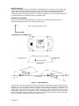
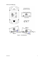
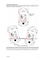
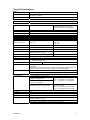
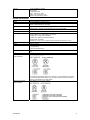
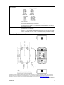
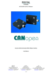
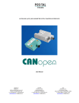
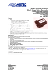
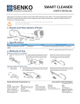
TECHNICAL DATASHEET #TDAX06025X Inclinometer CANopen®, 2 5-pin M12 Connectors P/N: AX06025X Features: 1 or 2 axis inclination or slope sensors 2 axis (-80º…80º), functional up to +90 º 1 axis, vertically positioned (-180º …180º or 0…360º) High resolution and accuracy Option: Three 0-5VDC outputs for direct connection to an analog monitoring control Option: RS232 output CANopen® (SAE J1939 models also available) 12V, 24VDC nominal Aluminum enclosure with 2 integral M12 5-pin connector(s) IP67 protection (Option: D version for underwater applications) .EDS provided to interface to standard CANopen® tools for user programmability Applications: Industrial Automation, Cranes, Hoists, Utility Vehicles, Off-highway, Ag, and Forestry Equipment Ordering Part Numbers: Inclinometers: AX060250 (D) – Inclinometer, CANopen®, 2 5-pin M12 Connectors (For a model with 1 Deutsch IPD DT15-4P connector, refer to TDAX06045X.) AX060251 (D) – Inclinometer, CANopen®, 3 Analog Outputs, 2 5-pin M12 Connectors AX060252 (D) – Inclinometer, CANopen®, 1 RS-232, 2 5-pin M12 Connectors Note: (D) refers to a version for underwater applications. Please add D to the p/n to order this version. Accessories: AX070114 - A mating plug with CAN termination, P/N: AX070114, can be ordered to plug the 2nd connector for applications requiring only one CAN and Power connection as well as requiring a termination of the CAN network. Mating cables are not supplied. Documentation: EDS File User Manual UMAX06025X-45X. Description: The inclinometer is designed to accurately measure inclination angles in two directions X and Y in the range of ±80º. The CANopen® device profile for inclinometers [DS-410], defines the X-axis as the longitudinal measurement, and the Y-axis as the lateral measurement. For both axes, the range of measurement is up to ±90º. If vertically installed, the sensor can also measure an inclination angle in one sensing direction in the ±180º (0-360º) range. The angles are measured by a two-axis MEMS sensor, which senses acceleration caused by the gravity force in two orthogonal directions. The sensor provides two output signals corresponding to each sensing direction. The output signals from the MEMS sensor are normalized and processed by a powerful microcontroller to receive inclination angles. The resolved angles can be then sent to the CAN bus, RS232 port (AX060252 only) or output as voltages (AX060251 only). The inclinometer alsos support a variety of extra features that makes it a more versatile sensor. Several of the optional Communication objects outlined in DS-301 are supported by the Inclinometer beyond those referenced in the device profile DS-410. The unit has user programmable functionality using SDO object access, per CiA DS-301. An .EDS file is provided to interface to standard CANopen ® tools. The standard inclinometer is IP67 rated and is packaged in a cast Aluminum housing with 2 M12 5-pin connectors. Note: CANopen® is a registered community trade mark of CAN in Automation e.V. Other Functions Using standard CANopen tools, the inclinometer can be reprogrammed for another function. Besides using CAN to output angles, the inclinometer can work as a CAN bus reader, presenting CAN input signals as voltages at any of the inclinometer signal voltage outputs. It can also send CAN input signals as text messages using the inclinometer RS-232 port. In a tilt sensor application, an out-of-range state (signal) can be transmitted at one of its voltage outputs in the AX060251 model. Standard Functionality There are two identical functional blocks: Sensor X and Sensor Y presenting angular data from two orthogonal sensing directions X and Y of the inclinometer sensor. X Figure 1.0 Sensing Direction Vectors Y Longitudinal (X) Axis Measuring Figure 2 – X-Axis Mounting The inclinometer measures angles between the sensing directions and the ground plane (relative to gravity). Normally, the sensor is mounted horizontally, with the sensing direction vectors being in parallel with the ground plane. This initial sensor position corresponds to the zero degree inclination on both axes. The zeroed value may be set after the sensor has been mounted by writing to object 6012h for the X-axis (longitudinal) or 6022h for the Y-axis (lateral). When a sensing direction vector points up, out of the ground plane, the inclination angle is considered to be positive, and when the sensing direction vector points down, into the ground plane, it is negative, as shown in Figures 2 and 3. TDAX06025X 2 Lateral (Y) Axis Measuring Figure 3 – Y-Axis Mounting TDAX06025X 3 Vertical Mount (360º) Measuring This functional block is used only when the inclinometer is mounted vertically, i.e. orthogonally (at 90º) to the ground plane. In this position, if kept vertical, the inclinometer can measure an inclination angle in one direction in the whole ±180º (0-360º) degree range. Figure 4 – Vertical Mounting The sensing direction of the vertically mounted sensor is the same as the Y sensing direction of the regularly (horizontally) mounted sensor. When the X sensing direction points up and the Y sensing direction points to the right, and is in parallel with the ground plane, the inclination angle is zero. The counterclockwise rotation of the sensor produces positive angles and the clockwise, correspondingly, negative, as shown in Figure 4. TDAX06025X 4 Technical Specifications: Input Power Supply Input Supply Current Protection 12V, 24V nominal (9…43 VDC power supply range) 40 mA at 12 V Typical 22 mA at 24 V Typical Reverse polarity and transient protection is provided. Outputs Operation Modes Dual Axis or Single Axis Single Axis – Angle Range Single Axis: -180º…180º (0…360º) Resolution Initial Accuracy Repeatability Nonlinearity ±0.05º Maximum ±0.25º Maximum, at 25ºC ±0.05º Maximum ±0.1º Typical Dual Axis – Angle Range Dual Axis: -80º…80º Functional up to ±90º Dual Axis Measurement Range Low-angle range -30º…30º High-angle range -80º…-30º 30º…80º Vertical position of the inclinometer should be maintained within the maximum displacement angle (±20º, by default) Resolution ±0.05º Maximum ±0.2º Maximum Initial Accuracy ±0.25º Maximum, at 25ºC ±0.5º Maximum, at 25ºC Repeatability ±0.05º Maximum ±0.2º Maximum Temperature Drift ±0.0015 º/ ºC Typical, at 0º over the full temperature range -40…85ºC - Nonlinearity Cross-Axis Sensitivity ±0.1º Typical 0.5% Typical ±0.25º Typical Cut-off frequency, Fc 5 Hz (default) 1…20 Hz (User configurable) 0.3 sec. Typical at Fc > 5Hz from 0 to 95% of the static output value Settling Time CAN Protection Output Voltages 1 CAN port CANopen® By default, the inclinometer transmits longitudinal and lateral angles (objects 6010h and 6020h) on TPDO1 to the CAN network, according to CiA Standard DS-410. Short circuit to ground Connection to the power supply (24V maximum) In P/N: AX060251: 3 Analog (0-5V) Voltage Output 1: Sensor X Angle (default) Voltage Output 2: Sensor Y Angle (default) Voltage Output 3: Vertical Mount Sensor Angle (default) Maximum Output Current Resolution Initial Accuracy Temperature Drift Protection TDAX06025X Dual-axis mode -90º 0 V (default, user configurable) 90º 5 V (default, user configurable) Axis direction is the same as the Y-axis in the dual-axis mode -180º 0 V (default, user configurable) 180º 5 V (default, user configurable) 5mA per channel 1 mV 0.15% @25ºC 30 ppm/ ºC over the full temperature range -40…85ºC Overcurrent (short circuit) Current is limited at 11.5mA Connection to the power supply. Connection to a reverse polarity voltage source (24V maximum) 5 RS-232 In P/N: AX060252: 1 RS-232 Text Format 115200 Baud Rate Data – 8 bit, Parity – None, Stop – 1 bit. Flow Control – No. Short circuit protection to ground. General Specifications Microprocessor Sensor Control Logic Node ID and Baudrate User Interface Operating Conditions Packaging Protection Weight Vibration Shock Approvals Electrical Connections Model AX060250 32-bit, 128 KByte flash program memory Dual axis MEMS acceleration sensor User programmable functionality using SDO object access, per CiA DS-301 Refer to UMAX06025X-45X for details. By default, the inclinometer ships factory programmed with a Node ID = 127 (0x7F) and with Baudrate = 125 kbps. These parameters are user programmable. .EDS provided to interface to standard CANopen® tools -40 to 85 C (-40 to 185 F) Cast Aluminum enclosure 2 Round M12 5-pin A-coded integral connector(s) CONEC P/N: 43-02079 (M12 FEMALE) CONEC P/N: CONEC 43-02080 (M12 MALE) Encapsulated, Lid Gasket Dimensions: 2.90 x 5.35 x 1.42 inches 73.66 x 135.99 x 36.16 mm (L x W x H) IP65 (IP67 on request for underwater applications) 0.85 lbs, 0.39 kg MIL-STD-202G, Test 204D and 214A (Sine and Random) 10 g peak (Sine) 7.86 Grms peak (Random) MIL-STD-202G, Test 213B 50g CE marking A mating plug with CAN termination, P/N: AX070114, can be ordered to plug the 2nd connector for applications requiring only one CAN and Power connection as well as requiring a termination of the CAN network. Electrical Connections Model AX060251 TDAX06025X 6 Electrical Connections Model AX060252 Installation Mounting holes accept #10 or M5 screws. The thickness of the mounting flange is 0.13 inch or 3.18 mm. The CAN wiring is considered intrinsically safe. All field wiring should be suitable for the operating temperature range of the module. Network Termination All chassis grounding should go to a single ground point designated for the machine and all related equipment. The CAN port is electrically isolated from all other circuits. Refer to the CAN 2.0B specification for more information. It is necessary to terminate the network; therefore an external CAN termination is required. No more than two network terminators should be used on any one single network. A terminator is a 121Ω, 0.25 W, 1% metal film resistor placed between CAN_H and CAN_L terminals at the end two nodes on a network. Dimensional Drawing Specifications are indicative and subject to change. Actual performance will vary depending on the application and operating conditions. Users should satisfy themselves that the product is suitable for use in the intended application. All our products carry a limited warranty against defects in material and workmanship. Please refer to our Warranty, Application Approvals/Limitations and Return Materials Process as described on www.axiomatic.com/service.html. Form: TDAX06025X-08/21/15 TDAX06025X 7