1
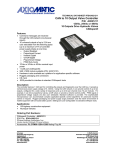
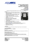
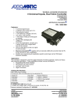
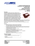
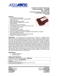
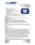
TECHNICAL DATASHEET #TDAX021901 8 In, 5 Output Valve Controller 6 Universal Analog Inputs, 1 Digital Input 1 Magnetic Pickup Sensor Input 4-2.5A Proportional or On/Off Outputs 1-2.5A Digital Output CANopen® P/N: AX021901 Features: Inputs: o 6 universal analog signal inputs (current, voltage, resistive, frequency, digital or PWM) o 1 digital input for enable/disable functionality o 1 magnetic pickup sensor input (RPM) Outputs: o 4 proportional or on/off valve drivers up to 2.5 A o Open or closed loop (PID) drive is user configurable. o 1 digital output up to 2.5A o Fully protected 1 CANopen® port (SAE J1939 model is p/n AX021900) 12V or 24Vdc nominal Rugged IP67 packaging and connectors for harsh environments Vibration compliant for mobile equipment applications Program the controller for a specific application using its predefined internal functional blocks and any commercially available CANopen® tool. Applications: The controller is designed for harsh operating environments. Typical applications can include: Industrial, off-highway (mobile) and marine applications for the control of hydraulic proportional poppet or spool valves Closed loop control of hydraulic valves Interface with a diesel engine’s electronic control module PWM signal to drive accessories Transmission controls Fan drive controls (on request) Vehicle traction control (on request) Ordering Part Numbers: CANopen® Valve Controller: AX021901 EDS File, UMAX021901: Downloadable from www.axiomatic.com. Go to the Log-In page and request the password from [email protected]. Accessories: Mating Plug Kit: PL-DTM06-12SA-12SB Description: The 8 Input, 5 Output Valve Controller (8i5o) is designed for versatile control of up to four proportional outputs to directly drive coils or other loads. Its flexible circuit design gives the user a wide range of configurable input or output types. The sophisticated control algorithms allow the user to program the controller for a wide range of applications without the need for custom software. The controller has six fully programmable universal inputs that can be setup to read: voltage; current; resistive; frequency; or digital input signals. For added flexibility, it also has a magnetic sensor circuit that can read AC signals and convert them into a frequency (RPM) pickup. Lastly, there is an eighth digital input that can be used for global enable/disable or overrides of one or all of the outputs. There are four universal outputs that can be setup to drive: proportional current (up to 2.5A each); hotshot digital current; proportional voltage (up to supply); proportional PWM; or straight on/off digital loads. For applications requiring a fifth digital output, there is also one high-side (sourcing) output for up to a 2.5A digital load. The 8i5o valve controller is highly programmable and allows the user to configure it for their application. Its sophisticated control algorithms allow for open or closed loop drive of the proportional outputs. It can be operated as either a self-contained control system, driving the outputs directly from the on-board inputs, and/or it can be integrated into a CANopen® network of controllers. All I/O and logical function blocks on the unit are inherently independent from one another, but can be programmed to interact in a large number of ways. Refer to the block diagram, Figure 1A, for the hardware features. Figure 1B shows the logical function blocks (software) available on the 8i5o. The 8i5o has a number of built-in protection features that can shut off the outputs in adverse conditions. They include hardware shutoffs to protect the circuits from being damaged as well as software shutdown features that can be enabled in safety critical systems. The various function blocks supported by the 8i5o are outlined below. The programmable internal architecture provides users with an ultimate flexibility, allowing them to build their own custom controller with a required functionality from a set of predefined internal functional blocks using any commercially available CANopen® tools. Table 1.0 – Pin out: AX021901 Pin # 1 2 3 4 5 6 7 8 9 10 11 12 Grey Connector Function CAN HI CAN LO CAN Shield Output GND Output GND BATT – (Output GND) BATT + LAMP Output 4 Output 3 Output 2 Output 1 TDAX021901 Pin # 1 2 3 4 5 6 7 8 9 10 11 12 Black Connector Function Analog Input 1 Analog Input 2 Analog Input 3 Analog Input 4 Analog Input 5 Analog Input 6 Digital Input 1 Magnetic Pickup Sensor Input Magnetic Pickup Sensor GND Analog GND Analog GND Analog GND 2 Figure 1A –Hardware Block Diagram TDAX021901 3 Figure 1B –Logical Functional Block Diagram 剌 TDAX021901 4 Technical Specifications: Inputs Power Supply Input - Nominal Protection CAN Input Grounds RPM Input Digital Input DI8 Universal Signal Inputs (Refer to Table 2.0.) 12V or 24Vdc nominal (9…60 Vdc power supply range) Reverse polarity protection is provided. Surge protection up to 75VDC is provided. Under-voltage shutdown protection of 7.5VDC is provided. Over-voltage shutdown protection is provided. The CANopen object dictionary of the 8i5o Controller is based on CiA device profile DS-404 V1.2 (device profile for Closed Loop Controllers). The object dictionary includes Communication Objects beyond the minimum requirements in the profile, as well as several manufacturer-specific objects for extended functionality. 3 GND connections are provided. 1 Magnetic Pickup Sensor Input Range: 0.5 Hz to 10 kHz; 100mV to 100V RMS 1 digital input, user selectable as: Active High/Active Low Configurable 10kOhm pullup or pulldown resistor Debouncing provided at 1 ms resolution 6 universal inputs are provided. Refer to Table 2.0. All input types are user selectable using a CANopen configuration tool as: Voltage; Current; Resistive; Frequency; RPM; PWM; or Digital. All analog inputs can be configured as active high digital. Inputs are sampled every 1 msec. Protected against shorts to GND or +Vcc Table 2.0 – Universal Input – User Selectable Parameters Voltage Input 0-1V (1 MΩ impedance) 0-2.5V (1MΩ impedance) 0-5V (150 KOhm impedance) 0-10V (133 KOhm impedance) Current Input Current sense resistor 124 Ω 0-20 mA 4-20 mA Resistive Input Self-calibrating for a range of 25Ω to 250 kΩ PWM Input 1 M Ω impedance 0 to 100% (at 10 Hz to 1kHz or 100 Hz to 10 kHz) Selectable 10kΩ pullup to +5V or pulldown to AGND resistor Frequency Input 1 MΩ impedance 0.5 Hz to 50 kHz range: 0.01 Hz resolution 10 Hz to 1kHz range: 0.1 Hz resolution 100 Hz to 10 kHz range: 1 Hz resolution Selectable 10kΩ pullup to +5V or pulldown to AGND resistor Digital Input Function 5V CMOS 1 MΩ impedance Active High for AI 1..AI7. Normal, Inverse or Latched (push-button) response Debouncing provided at 1 ms resolution Input Accuracy Input Resolution Error Detection/Reaction TDAX021901 Voltage: +/- 1% full scale error (all types) Current: +/- 2% full scale error Resistive: +/- 1% full scale error, self-calibrating throughout the range Frequency: +/- 1% full scale error (all ranges) PWM: +/- 1% full scale error (all frequencies) 12-bit Analog to Digital (voltage, current, resistive) 15-bit Timer (frequency, RPM, PWM) Voltage: 1mV, Current: 1uA, Resistive: 1Ω, PWM: 0.01% Frequency 0.5 to 50Hz Range: 0.01Hz resolution Frequency 10Hz to 1kHz Range: 0.1Hz resolution Frequency 100 Hz to 10kHz Range: 1Hz resolution Out of Range High and Low detection EMCY code generation (object 1003h) and fault reaction possible (1029h) Output(s) shutdown function can be enabled. 5 Outputs CAN The CANopen object dictionary of the 8i5o Controller is based on CiA device profile DS-404 V1.2 (device profile for Closed Loop Controllers). The object dictionary includes Communication Objects beyond the minimum requirements in the profile, as well as several manufacturer-specific objects for extended functionality. Four fully independent software controlled outputs selectable as: Proportional Current Hotshot Digital (See Figure 2.) PWM Duty Cycle Proportional Voltage On/Off Digital Half-bridge outputs, current sensing, grounded load. High side sourcing up to 2.5A Current sensing for close-loop control, current feedback on object 2370h High frequency output drive at 25kHz (except in PWM output mode) Universal Outputs Current Outputs: Software controlled PID current, Factory calibrated. User configurable. Fully configurable dither from 50 to 400Hz. Voltage Outputs: Average output based on unit power supply High frequency drive at 25kHz PWM Outputs: Configurable frequency ONLY if no voltage or current output types are used. Digital Output Dither Output GND Protection Output Accuracy Output Resolution Error Detection/Reaction Digital On/Off: Load at supply voltage must not draw more than 2.5A. High side sourcing up to 2.5A, grounded load Can be used to drive a diagnostic lamp Works with inductive or resistive loads Independent dithering is available on all four analog outputs. Fully configurable from 50Hz to 400Hz Adjustable amplitude up to 50% full scale 2 GND connections are provided. Fully protected against short circuit to ground and short circuit to power supply rail. Unit will fail safe in the case of a short circuit condition, self-recovering when the short is removed. Output Current mode +/-2% full scale error Output Voltage mode +/-5% full scale error Output PWM Duty Cycle mode +/-1% full scale error Current: 1mA, Voltage: 0.1V, PWM: 0.1% EMCY code generation (object 1003h) and fault reaction possible (1029h) when an open or short circuit is detected at the output (current mode only) Figure 2 – Hotshot Digital Output (User selectable) TDAX021901 6 General Specifications Microprocessor Control Logic Communications User Interface Diagnostics Operating Conditions Weight Protection Vibration and Shock Compliance TDAX021901 DSP56F8366 User programmable functionality is provided using SDO object access, per CiA DS-301. Refer to the user manual for details. (Application-specific control logic is available on request.) 1 CAN 2.0B port, protocol CiA CANopen ® – N.B. Default baud rate is 125kBit/s (user configurable). By default, the 8i5o Controller transmits measured input (FV object 7100h) and output current feedback (FV object 2370h) on TPDO1 The controller’s object dictionary is compatible with the CiA DS-404 device profile (Device profile for measurement devices and closed-loop controllers). In addition to the standard objects for this device profile, the controller also includes a number of manufacturer specific objects to extend the functionality beyond that of the basic profile. The Axiomatic AX021901 is compliant with the following CAN in Automation (CiA) standards. [DS-301] CiA DS-301 V4.1 – CANopen® Application Layer and Communication Profile. CAN in Automation 2002 [DS-404] CiA DS-404 V1.2 – Device Profile for Measurement Devices and Closed-Loop Controllers. CAN in Automation 2002 [DS-305] CiA DS-305 V2.0 – Layer Setting Service (LSS) and Protocols. CAN in Automation 2006 .EDS provided to interface to standard CANopen ® tools Refer to the User Manual. -40 to 85 C (-40 to 185 F) 0.55 lb. (0.25 kg) IP67 rating for the product assembly MIL-STD-202G, Test 204D, 214A and 213B 7.68 Grms (Random) 10 g peak (Sine) 50 g (Shock) 7 Electrical Connections Packaging and Dimensions Deutsch DTM series 24 pin receptacle (DTM13-12PA-12PB-R008) Mating plug: Deutsch DTM06-12SA and DTM06-12SB with 2 wedgelocks (WM12S) and 24 contacts (0462-201-20141). 20 AWG wire is recommended for use with contacts 0462-201-20141. Refer to Table 1.0 for the pin out. High Temperature Nylon housing - Deutsch IPD PCB Enclosure (EEC-325X4B) 4.62 x 5.24 x 1.43 inches 117.42 x 133.09 x 36.36 mm (W x L x H excluding mating plugs) Note: CANopen® is a registered community trade mark of CAN in Automation e.V. Specifications are indicative and subject to change. Actual performance will vary depending on the application and operating conditions. Users should satisfy themselves that the product is suitable for use in the intended application. All our products carry a limited warranty against defects in material and workmanship. Please refer to our Warranty, Application Approvals/Limitations and Return Materials Process as described on www.axiomatic.com/service.html. Form: TDAX021901-07/03/15 TDAX021901 8