1
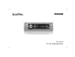
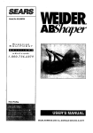
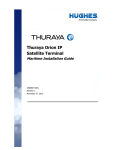
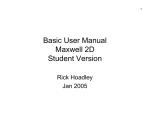
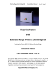
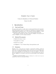
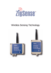
OUTDOOR INSTALLATION WARNING
IMPORTANT SAFETY PRECAUTIONS:
LIVES MAY BE AT RISK! Carefully observe these instructions and any special instructions that are included with the equipment
you are installing.
IMPORTANT: Look over the site before beginning any installation, and anticipate possible hazards, especially these:
CONTACTING POWER LINES CAN BE LETHAL. Make sure no power lines are
anywhere where possible contact can be made. Antennas, masts, towers, guy wires or cables
may lean or fall and contact these lines. People may be injured or killed if they are touching or
holding any part of equipment when it contacts electric lines. Make sure there is NO possibility
that equipment or personnel can come in contact directly or indirectly with power lines.
Assume all overhead lines are power lines.
The horizontal distance from a tower, mast or antenna to the nearest power line should be at least twice the total length of the
mast/antenna combination. This will ensure that the mast will not contact power if it falls either during installation or later.
TO AVOID FALLING, USE SAFE PROCEDURES WHEN WORKING AT HEIGHTS ABOVE GROUND.
•
•
•
•
•
•
Select equipment locations that will allow safe, simple equipment installation.
Don’t work alone. A friend or co-worker can save your life if an accident happens.
Use approved non-conducting ladders and other safety equipment. Make sure all equipment is in good repair.
If a tower or mast begins falling, don’t attempt to catch it. Stand back and let it fall.
If anything such as a wire or mast does come in contact with a power line, DON’T TOUCH IT OR ATTEMPT TO
MOVE IT. Instead, save your life by calling the power company.
Don’t attempt to erect antennas or towers on windy days.
MAKE SURE ALL TOWERS AND MASTS ARE SECURELY GROUNDED, AND ELECTRICAL CABLES
CONNECTED TO ANTENNAS HAVE LIGHTNING ARRESTORS. This will help prevent fire damage or human injury
in case of lightning, static build-up, or short circuit within equipment connected to the antenna.
•
•
•
The base of the antenna mast or tower must be connected directly to the building protective ground or to one or more
approved grounding rods, using 1 OAWG ground wire and corrosion-resistant connectors.
Refer to the National Electrical Code for grounding details.
Lightning arrestors for antenna feed coaxial cables are available from HyperLink Technologies, Inc.
IF A PERSON COMES IN CONTACT WITH ELECTRICAL POWER, AND CANNOT MOVE:
•
•
•
DON’T TOUCH THAT PERSON, OR YOU MAY BE ELECTROCUTED.
Use a non-conductive dry board, stick or rope to push or drag them so they no longer are in contact with electrical power.
Once they are no longer contacting electrical power, administer CPR if you are certified, and make sure that emergency
medical aid has been requested.
Copyright © This drawing is property of L-com Global Connectivity. All rights reserved.
L-COM, INC. 45 BEECHWOOD DRIVE NORTH ANDOVER, MA 01845
WWW.L-COM.COM E-MAIL: [email protected] PHONE: 1-800-343-1455 FAX: 1-978-689-9484
© L-com, Inc. All Rights Reserved. L-com Global Connectivity and the L-com logo are registered marks.
End-User Manual
Model HA2401-XI-325X
FCC ID: MYF-XI-325X
IC: 2837A- XI-325X
Interference Statement
This device complies with Part 15 of the FCC Rules and with RSS-210 of Industry Canada.
Operation is subject to the following two conditions: (1) this device may not cause harmful
interference, and (2) this device must accept any interference received, including interference
that may cause undesired operation.
Warning: Changes or modifications not expressively approved by the party responsible
for compliance could void the user’s authority to operate the equipment.
The term “IC:” before the radio certification number only signifies that Industry Canada
technical specifications were met.
Information to the user
NOTE: This equipment has been tested and found to comply with the limits for a Class
B digital device, pursuant to Part 15 of the FCC Rules. These limits are designed to
provide reasonable protection against harmful interference in a residential installation.
This equipment generates, uses, and can radiate radio frequency energy. If not
installed and used in accordance with the instructions, it may cause harmful
interference to radio communications. However, there is no guarantee that
interference will not occur in a particular installation. If this equipment does cause
harmful interference to radio or television reception, which can be determined by
turning the equipment off and on, the user is encouraged to try and correct the
interference by one or more of the following measures:
Reorient or relocate the receiving antenna.
Increase the distance between the equipment and the receiver.
Connect the equipment to an outlet on a circuit different from that to which the receiver
is connected.
Consult the dealer or an experienced radio/TV technician for help.
Copyright © This drawing is property of L-com Global Connectivity. All rights reserved.
L-COM, INC. 45 BEECHWOOD DRIVE NORTH ANDOVER, MA 01845
WWW.L-COM.COM E-MAIL: [email protected] PHONE: 1-800-343-1455 FAX: 1-978-689-9484
© L-com, Inc. All Rights Reserved. L-com Global Connectivity and the L-com logo are registered marks.
Any changes or modifications of equipment not expressly approved by the
manufacturer could void the user’s authority to operate the equipment and the
company’s warranty.
The device and its antenna and must not be co-located or operating in
conjunction with any other antenna or transmitter.
When this device is installed either as a fixed-mount or mobile application there
is a minimum required separation distance of 20 cm from users.
For further information contact:
Hyperlink Technologies, Inc.
Technical Support Department
1201 Clint Moore Road
Boca Raton, FL 33487
Email: [email protected]
Copyright © This drawing is property of L-com Global Connectivity. All rights reserved.
L-COM, INC. 45 BEECHWOOD DRIVE NORTH ANDOVER, MA 01845
WWW.L-COM.COM E-MAIL: [email protected] PHONE: 1-800-343-1455 FAX: 1-978-689-9484
© L-com, Inc. All Rights Reserved. L-com Global Connectivity and the L-com logo are registered marks.
When locating the antenna or operating this device you must observe the following
exposure limits:
When this device is installed either as a fixed-mount or mobile application there
is a minimum required separation distance of 20 cm from users.
Non-Amplified Systems:
For non-amplified systems simply plug the antenna connector into the antenna port on
the PC card and proceed to PC Card and Software Installation on the next page.
Amplified Systems:
Amplifier connections are clearly labeled on the amplifier unit as shown below.
1. Connect the antenna to the amplifier output labeled “ANTENNA”.
2. Connect the PC Card to the Amplifier input labeled “RADIO” using the pigtail cable.
3. Plug the AC adapter into the amplifier’s DC power jack and wall outlet.
Proceed to PC Card and Software Installation on the next page.
Copyright © This drawing is property of L-com Global Connectivity. All rights reserved.
L-COM, INC. 45 BEECHWOOD DRIVE NORTH ANDOVER, MA 01845
WWW.L-COM.COM E-MAIL: [email protected] PHONE: 1-800-343-1455 FAX: 1-978-689-9484
© L-com, Inc. All Rights Reserved. L-com Global Connectivity and the L-com logo are registered marks.
PC Card and Software Installation
I. Network Configuration
XI-325 is an IEEE802.11b-compliant PCMCIA Type II DSSS wireless LAN PC card.
It fully supports wireless networking under Windows 95/98/2000/XP and NT 4.0.
XI-325 can be operated in Ad-Hoc and Infrastructure network configurations. Ad-Hoc mode
allows XI-325 users to join an Basic Service Set (i.e., peer-to-peer mode, without access point).
Infrastructure mode allows XI-325 users to join a Extended Basic Service Set (i.e., connect to
access point)
II. Package Content
XI-325 11 Mb PC Card
Antenna
Amplifier Kit (Optional)
III. XI-325 and Utility Installation under Windows
1. Download XI-325 PC-Card drivers and utility zip file and extract files.
2. Insert the XI-325 card into the PCMCIA slot, then start Windows. Windows will autodetect new hardware and Windows Wizard will display “New Hardware Found”.
3. Click on ‘Next’
4. Once [Insert Win 95/98/2000/XP CD-Rom into appropriate drive, then click ‘OK’]
window appears, please follow by either inserting the Windows CD-Rom or finding the
Windows source path within the appropriate drives, then click ‘OK’.
5. Click ‘Finish’ to complete the installation. Restart Windows.
6. To install the XI-325 Utility, go to the ‘Utility’ folder from the downloaded zip file, then
execute setup.exe.
7. Follow the on-screen instructions to complete utility installation, then afterward doubleclick on
Copyright © This drawing is property of L-com Global Connectivity. All rights reserved.
L-COM, INC. 45 BEECHWOOD DRIVE NORTH ANDOVER, MA 01845
WWW.L-COM.COM E-MAIL: [email protected] PHONE: 1-800-343-1455 FAX: 1-978-689-9484
© L-com, Inc. All Rights Reserved. L-com Global Connectivity and the L-com logo are registered marks.
the Utility icon. Utility interface will then appear and configuration can be accomplished here.
IV. Using Utility to Set Up Ad-Hoc Network
If wireless LAN has already been set up, simply plug in XI-325.
network by taking the following steps:
1.
Otherwise, set up a wireless
On the main utility interface, click on [Diagnostic tools], then click on [Site Survey].
This would disable wireless network links temporarily and display channel quality.
Please note that the blue bars indicate the best quality channels.
Note that amplified kits are shipped factory set to channel 6 and can not be changed.
2. Back on the main utility interface, click on [Network Configuration] and “Configure the
Adapter” window will appear. Setup procedures are as follows:
1) ESSID denotes the assigned name for the designated wireless LAN. If ESSID differs,
then wireless connection between wireless end devices will not be accomplished.
Please note that selecting [Use Non-Specified ESSID: ANY] will possibly be connected
to other wireless LAN. Therefore, ESSID setup is highly recommended.
Example: Specify ESSID as : TEST001.
Notice: Once the ESSID is set on the initial XI-325, and while the rest of the ESSID
remains as default value ANY, then the initial XI-325 with the ESSID must be started
first.
2) Select [Ad-Hoc] under ‘Network Type’, select the Channel in step 1 for [Ad-Hoc
Default Channel] (Note: Only channel 6 is selectable for amplified systems).
(Notice: Under Ad-Hoc, it would require a single uniform channel to enable a wireless
networking group).
3) Use WEP ** (will be available soon). The default is ‘ Disable’. If you require high
security in transmission, please select the “Enable” item and select [Encryption].
When you enter encryption configuration, you can type keyword and press [Generate]
to create 4 new encryption keys and select one of them to scramble your transmission
data.
Notice: When your use WEP to communicate with the other wireless clients, all the
wireless devices in this network must have the same encryption key and keyword.
4) Upon completing steps 1~3, click on [Modify] to save altered values.
V. Using Utility to Connect to Access Points
1. On the main Utility interface, click on [Diagnostic Tools], then click on [Access Point
Browser]. This would disable wireless connection temporarily and the subsequent display
Copyright © This drawing is property of L-com Global Connectivity. All rights reserved.
L-COM, INC. 45 BEECHWOOD DRIVE NORTH ANDOVER, MA 01845
WWW.L-COM.COM E-MAIL: [email protected] PHONE: 1-800-343-1455 FAX: 1-978-689-9484
© L-com, Inc. All Rights Reserved. L-com Global Connectivity and the L-com logo are registered marks.
would show status for all available access points.
By using this tool, it is possible to find
out ESSID for the connected wireless group.On the main Utility interface, click on [Network
Configuration] and configuration screen will appear. Setup procedures are as follows:
1) ESSID denotes the assigned name for the designated wireless LAN.
If ESSID differs,
then wireless connection between wireless end devices will not be accomplished.
Please note that selecting [Use Non-Specified ESSID: ANY] will possibly be connected
to other wireless LAN with different ESSID. Therefore, ESSID setup is highly
recommended. Example : Specify ESSID as : TEST001.
Notice: If the ESSID of PC card remains as default value ANY, then the PC card is
possible to be connected to all available Access Points.
2) Select [Infrastructure] under ‘Network Type’
3) Use WEP ** (will be available soon). The default is ‘ Disable’. If you require high
security in transmission, please select the “Enable” item and select [Encryption]. When you
enter encryption configuration. You can type keyword and press [Generate] to create 4 new
encryption keys and select one of them to scramble your transmission data.
Notice: When your use WEP to communicate with the other wireless clients, all the wireless
devices in this network must have the same Encryption Key and keyword. )
4) Upon completing steps 1~3, click on [Modify] to save altered values.
Infrastructure network configuration provides roaming to mobile users. Multiple (at
least 2) AP connection allows LANEscape users to access seamless wireless connection
while moving freely within the coverage area. To enable Extended Service Sets (ESS),
all LANEscape wireless end devices (XI-325, AP, etc.) will have to be under same
ESSID.
Utility Information
Copyright © This drawing is property of L-com Global Connectivity. All rights reserved.
L-COM, INC. 45 BEECHWOOD DRIVE NORTH ANDOVER, MA 01845
WWW.L-COM.COM E-MAIL: [email protected] PHONE: 1-800-343-1455 FAX: 1-978-689-9484
© L-com, Inc. All Rights Reserved. L-com Global Connectivity and the L-com logo are registered marks.
ESSID
Select the wireless network group to join
(“ANY” is default setting).
Network Type Select the station operation mode,
Ad-Hoc: (without Access Point)
Infrastructure: (with Access Point, default
setting).
RTS Threshold To solve the “Hidden Node Problem” (Default
setting : “Disable”)
Network
Frag Threshold To obtain better performance if XI325
Configuration
always transmits large files in wireless LAN.
(Default setting : “Disable”)
Use WEP
To have high security in transmission.
(will be
(Default setting : “Disable”)
available soon)
Power Save
To make power management.
(Default setting : “Disable”)
Transmission Select the transmission rate
Rate
(Default setting : “Fully Auto”)
Site Survey
Inspect channel quality for your site.
Link Quality Inspect the point-to-point data transmission
Diagnostic
Test
quality between two wireless LAN stations.
Tools
Access Point To browser all the active Access Points in this
Browser
environment.
Copyright © This drawing is property of L-com Global Connectivity. All rights reserved.
L-COM, INC. 45 BEECHWOOD DRIVE NORTH ANDOVER, MA 01845
WWW.L-COM.COM E-MAIL: [email protected] PHONE: 1-800-343-1455 FAX: 1-978-689-9484
© L-com, Inc. All Rights Reserved. L-com Global Connectivity and the L-com logo are registered marks.
7
8
HG2407U
HG2408U
N/A
N/A
N/A
N/A
21.2
21.2
20.0
17.8
15.9
14.1
14.1
14.1
11.2
11.2
11.2
10.0
N/A
N/A
N/A
N/A
17.6
15.7
12.5
11.1
29
8.9
28
N/A
N/A
22.4
18.9
18.9
17.8
15.9
14.1
12.6
12.6
12.6
10.0
10.0
10.0
8.9
8.0
Appendix A
27
N/A
25.1
20.0
16.8
16.8
15.9
14.1
12.6
11.2
11.2
11.2
8.9
8.9
8.9
8.0
7.1
26
24
25.1
17.8
14.1
11.9
11.9
11.2
10.0
8.9
8.0
8.0
8.0
6.3
6.3
6.3
5.6
5.0
21.8
19.5
13.8
11.0
9.2
9.2
8.7
7.8
6.9
6.2
6.2
6.2
4.9
4.9
4.9
4.4
3.9
-
-
3.0
-
-
-
-
-
-
-
3.8
3.8
3.8
3.0
3.0
2.7
17.5
C a rd A lone
Copyright © This drawing is property of L-com Global Connectivity. All rights reserved.
31.7
22.4
17.8
15.0
15.0
14.1
12.6
11.2
10.0
10.0
10.0
8.0
8.0
8.0
7.1
6.3
L-COM, INC. 45 BEECHWOOD DRIVE NORTH ANDOVER, MA 01845
WWW.L-COM.COM E-MAIL: [email protected] PHONE: 1-800-343-1455 FAX: 1-978-689-9484
© L-com, Inc. All Rights Reserved. L-com Global Connectivity and the L-com logo are registered marks.
Configurations with N/A are not permissible, via. FCC 15.247(b)(4)(i)
Configurations in RED can only be used in FIXED MOUNTED Installations
Configurations in BLACK Can be used in either MOBILE OR FIXED MOUNTED Installations
12
15
6
HG2406U
HG2412U
HG2415U-PRO
5
10
N/A
5
RE05U
HG2405
HG2410U
N/A
5
RE05E
8.5
15.7
3
8.5
15.7
3
HG2403UR
HG2404CU
HG2409U
12.5
3
HG2403RD
HGV-2409U
12.5
2
HG2402RD
9.9
1
HG2401U
29.9
Gain (dBi)
Antenna Model
Appendix A - Minimum Separation Distance (cm)
A mplifie r P owe r R a ting ( dB )
www.L-com.com
FCC / IC Compliant Configurations - Channels of Operation
Amplifier Power Rating
1000
800
630
500
400
Gain (dBi)
29.9
29
28
27
26
1
6
6
6
6
6
2
6
6
6
6
6
3
6
6
6
6
6
3
6
6
6
6
6
3
6
6
6
6
6
5
6
6
6
6
6
5
6
6
6
6
6
5
6
6
6
6
6
6
6
6
6
6
6
7
N/A
6
6
6
6
8
N/A
6
6
6
6
8.5
N/A
6
6
6
6
8.5
N/A
6
6
6
6
10
N/A
N/A
6
6
6
12
N/A
N/A
N/A
6
6
15
N/ A
N/A
N/A
N/A
6
Channel
1
2
3
4
5
6
7
8
9
10
11
Frequency (MHz)
2412
2417
2422
2427
2432
2437
2442
2447
2452
2457
2462
250
24
6
6
6
6
6
6
6
6
6
6
6
6
6
6
6
6
150
21.8
6
6
6
6
6
6
6
6
6
6
6
6
6
6
6
6
Card Alone
(mW) - as labeled
17.5
(dBm)
1-11
1-11
1-11
1-11
1-11
1-11
1-11
-
L-COM, INC. 45 BEECHWOOD DRIVE NORTH ANDOVER, MA 01845
WWW.L-COM.COM E-MAIL: [email protected] PHONE: 1-800-343-1455 FAX: 1-978-689-9484
© L-com, Inc. All Rights Reserved. L-com Global Connectivity and the L-com logo are registered marks.
Copyright © This drawing is property of L-com Global Connectivity. All rights reserved.
Configurations in BLACK can be used in either MOBILE OR FIXED MOUNTED Installations (FILTER REQUIRED)
Configurations in BLUE can be used in either MOBILE OR FIXED MOUNTED Installations (NO FILTER REQUIRED)
Configurations in RED can only be used in FIXED MOUNTED Installations (FILTER REQUIRED)
Configurations with N/A are NOT PERMISSIBLE, via. FCC 15.247(b)(4)(i)
Configurations with "-" are NOT PERMISSIBLE as they do not meet the FCC Part 15 restricted band limits
Antenna Model Antenna Type
HG2401U
whip/monopole
HG2402RD
whip/monopole
HG2403RD
whip/monopole
HG2403UR
whip/monopole
HG2404CU
whip/monopole
RE05E
whip/monopole
RE05U
whip/monopole
HG2405
whip/monopole
HG2406U
whip/monopole
HG2407U
whip/monopole
HG2408U
whip/monopole
HG2409U
whip/monopole
HGV-2409U
whip/monopole
HG2410U
whip/monopole
HG2412U
whip/monopole
HG2415U-PRO whip/monopole
Appendix B
www.L-com.com