1
BSC-HT Haas Top
9
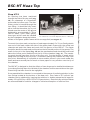
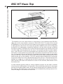
An opening has been machined
through the side of the top unit (Fig.
4b) for placement of a thermistor
probe near the inflow port. The thermistor probe is inserted through the
luer fitting. It should be fully inserted so that the thermistor tip is positioned near the center of the groove
designed to accommodate it. Slices
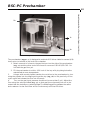
rest on elastic nylon mesh (pantyFigure 5.
hose type) which must be installed
The BSC-BU with BSC-HT, BSC-ZT and BSC-PC
by the investigator along the bottom
surface of the green plastic frames which are supplied (see Figure 6).
To mount the nylon mesh,cut a piece of mesh approximately 5 x 11 cm.Gently stretch
one end of the mesh under the side of the green plastic frame with the milled out
channels and push the frame and mesh into the groove of the BSC-HT. The frame
should be above the mesh and positioned on the horizontal portion of the groove. The
small circles cut in the frame (Fig. 4d) are the prechambers and should be positioned
above the inflow ports (farthest from the lip of the chamber) (Fig. 4e). The remaining mesh should hang over the lip of the top unit. Cut the section of mesh which
hangs over the edge to form a point. The solution leaving the chamber will drip from
this point. Alternatively, it is possible to use a smaller piece of nylon mesh under the
frame and use a second piece of mesh or tissue paper to carry solution over the lip of
the chamber.
The BSC-HT is designed so that the effects of two drugs can be studied simultaneously-one drug flowing down the left side of the chamber and the second down the right.
Intermixing has been found to be negligible.
Once assembled, the chamber is connected to the sources of perfusing solution by the
luer fittings located at the bottom of the base unit. Flow rates of 0.5 mil/min per
chamber can be obtained by keeping the solutions in bottles pressurized to approximately 0.2 kg/CM2 by a 95% O2/5% CO2 gas mixture. Electronically switched valves
are recommended for solution changes to minimize disruption of solution flow.
Harvard Apparatus Brain Slice Chamber System User's Manual
Step HT-2