1
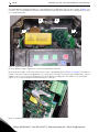
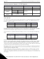
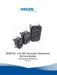
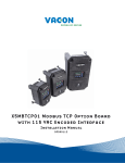
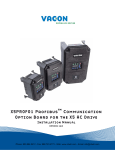
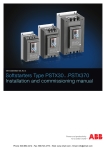
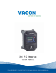
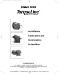
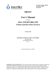
X5OPT01 115 VAC Encoder Interface
Option Board
Installation Manual
DPD00113
Phone: 800.894.0412 - Fax: 888.723.4773 - Web: www.clrwtr.com - Email: [email protected]
X5OPT01 115 VAC / Encoder Interface Option Board
vacon
3
Installing the X5OPT01 115 VAC /
Encoder Interface Option Board
Introduction
The X5OPT01 provides the option of controlling X5 AC drives from 115 VAC control signals, or to connect a shaftmounted encoder to the drive to improve speed regulation. A maximum of five channels of 115 VAC control is
available for use in selecting direction, preset speeds, or other drive functions.
With this option, an encoder with a nominal rating of up to 2048 pulses per revolution can be connected to the X5
unit to improve speed load regulation of the drive. Overall encoder frequency at maximum process speed must be
limited to 100kHz.
This option also provides two additional control relays, each rated for 115 VAC, 1 amp, or for 230 VAC, 0.5 amp.
Applicable Documents
This manual is supplied as a supplement to the X5 AC Drive User’s Manual (DPD 00089, previously Form 1434).
Option Kit Contents
The option kit includes the following materials:
Part Number
Description
25100079C
115 VAC / Encoder Option Board
32100391
Flexible cable assembly
Phone: 800.894.0412 - Fax: 888.723.4773 - Web: www.clrwtr.com - Email: [email protected]
4
X5OPT01 115 VAC / Encoder Interface Option Board
vacon
Installation Procedures
!
WARNING
SENSITIVE EQUIPMENT
This assembly contains static-sensitive components. It should be handled only by a static-safe installer,
using a grounded wrist strap.
Failure to observe this precaution may cause premature equipment failure.
!
DANGER
HAZARDOUS VOLTAGE
• Disconnect all power before servicing a drive unit or its components. WAIT 5 MINUTES until the DC
bus capacitors discharge.
• Ensure that any other power sources that may feed control logic have been disconnected.
• DO NOT short across DC bus capacitors or touch unshielded components or terminal strip screw
connections with voltage present.
• Install all covers before applying power or starting and stopping the drive.
• The user is responsible for conforming to all applicable code requirements with respect to grounding
all equipment.
• Many parts in a drive, including printed circuit boards, operate at line voltage. DO NOT TOUCH. Use
only electrically-insulated tools.
Before servicing any drive.
• Disconnect all power.
• Place a “DO NOT TURN ON” label on the drive disconnect.
• Lock the disconnect in the open position.
Failure to observe these precautions will cause shock or burn, resulting in severe personal injury
or death.
Figure 1 on page 5 illustrates the option board and the location of the terminals and the power supply selector.
Phone: 800.894.0412 - Fax: 888.723.4773 - Web: www.clrwtr.com - Email: [email protected]
X5OPT01 115 VAC / Encoder Interface Option Board
vacon
Encoder / 115 VAC Interface
Control Relay Terminals
Encoder Interface Power
Supply Selector
Figure 1: Option Board Layout
Before you can install the option board, you must first remove the drive cover.
Figure 2 shows the locations of the cover screws. The torque range for the X5 Size 1 cover is 18-26 in/lbs.
Cover screw locations
Cover screw locations
Figure 2: Cover Assembly and Screw Locations
Phone: 800.894.0412 - Fax: 888.723.4773 - Web: www.clrwtr.com - Email: [email protected]
5
6
X5OPT01 115 VAC / Encoder Interface Option Board
vacon
The option board is installed just above the control board in all configurations (a Size 1 unit is shown in Figure 3 for
reference). The screws labeled “A” must be removed from the drive unit; those labeled “B” need only to be loosened
to accept the board slot.
.
B
B
A
A
Figure 3: Option Mounting Locations
Once the board is in place, tighten the screws to a maximum of 26 in-lbs.
Next, install the flexible circuit to finish the interface to the control board. (Refer to Figure 4 on page 6.) To install the
flexible circuit, first remove the keypad frame (necessary in this size unit). The frame is attached with two screws in
opposite corners; the screws thread into fasteners in the plastic assembly. After the flexible circuit is installed,
replace these screws, limiting the installation torque to 12 in-lbs..
Figure 4: Flexible Circuit Interface to Control Board
Phone: 800.894.0412 - Fax: 888.723.4773 - Web: www.clrwtr.com - Email: [email protected]
X5OPT01 115 VAC / Encoder Interface Option Board
vacon
7
115 VAC Interface / Relay / Encoder Interface Terminals
The X5OPT01 option kit includes five 115 VAC inputs, two additional
programmable relays, and an encoder interface. The details of the terminals on
the board related to the 115 VAC interface and the encoder are shown in the
following table:
Terminal
Figure 5: 115 VAC Interface /
Encoder Terminals
Note that the connections
described in Table 1 work only
when the encoder has an internal
pull-up resistor on the open collector. Alternatively, it might be
preferable to pull the + channel
high, and attach the open collector to the - channel. For example,
if using Channel A, A+ on the
option board would be tied to
VDC, and A- would be connected
to the open collector coming
from the encoder. The advantage
in this method is that no pull-up/
down resistors are needed; if the
encoder has an internal pull-up,
this does not affect anything.
Description
DI-A
DI-B
DI-C
DI-D
DI-E
115 VAC logic input; connect input to 115 VAC to activate.
The programmable functionality of these inputs is controlled
by parameters 728, 729, 730, 731, and 732. Each of these
inputs can be disabled or configured to emulate the function
of the FWD, REV, R/J, EN, MOL, DI1, DI2, DI3, DI4, or DI5 input
terminals on the X5 control board.
Refer to the X5 User’s Manual for more information.
ACn
The neutral connection for the 115 VAC control inputs
NO3
RC3
NC3
The third auxiliary relay.
The function of this relay is set by parameter 709.
Functionally, it is capable of each of the features outlined in
the X5 User’s Manual under parameters 705-708.
Terminal NO3 is a normally-open contact; it will close when
the relay activates. NC3 is a normally-closed contact; it will
open when the relay activates. RC3 is the common terminal
associated with both contacts.
The ratings of these contacts are 115 VAC, 1 amp; and 230
VAC, 0.5 amp.
NO4
RC4
NC4
The fourth auxiliary relay.
The function of this relay is set by parameter 710.
Functionally, it is capable of each of the features outlined in
the X5 User’s Manual under parameters 705-708.
Terminal NO4 is a normally-open contact; it will close when
the relay activates. NC4 is a normally-closed contact; it will
open when the relay activates. RC4 is the common terminal
associated with both contacts.
The ratings of these contacts are 115 VAC, 1 amp; and 230
VAC, 0.5 amp.
A+
A-
Channel A input from the encoder. Compatible with line
driver, open collector, or totem pole outputs from an
encoder. If it is an open collector or totem pole-type, encoder
outputs are used; connect the A- terminal to Ecom.
B+
B-
Channel B input from the encoder. Compatible with line
driver, open collector, or totem pole outputs from an
encoder. If it is an open collector or totem pole-type, encoder
outputs are used; connect the B- terminal to Ecom.
C+
C-
Channel C input from the encoder, the home pulse.
Compatible with line driver, open collector, or totem pole
outputs from an encoder. If it is an open collector or totem
pole-type, encoder outputs are used; connect the Cterminal to Ecom.
VDC
Ecom
Power supply terminal for use with a customer-supplied
encoder. It can be either +12 VDC or +5 VDC based on the
position of the encoder interface power supply selector
shown in Figure 1. Voltage regulation: +/- 5%; maximum
current available is 100 mA.
Signal common for the encoder interface
Phone: 800.894.0412 - Fax: 888.723.4773 - Web: www.clrwtr.com - Email: [email protected]
8
X5OPT01 115 VAC / Encoder Interface Option Board
vacon
Specifications for Encoder / 115 VAC Interface
Encoder Interface
Speed regulation
115 VAC Interface
< 0.1 Hz (1)
On state
Input frequency (max.)
100 kHz
Off state
< 10 VAC
Input voltage
10-24 VDC +/- 5%
Input frequency
58-62 Hz
Suggested pull-up
resistor
Terminal block wire
limitations
5 VDC
500 ohms
12 VDC
1k ohms
24 VDC
3.3k ohms
12-24 AWG
90-140 VAC
On/off delay
30 ms maximum
Terminal block wire
limitations
12-24 AWG
(1) PID feedback plus optimal motor turning in SLV mode employed
Setup and Use
The encoder interface is most effective if used in conjunction with the vector mode of operation. Refer to Chapter 6
of the X5 User’s Manual for detailed information about using the vector mode. Three additional parameters are
provided to calibrate the encoder:
Parameter #
Parameter Name
Range
Default Value
219
Encoder Pulses per Revolution
0-16383
1024
220
Encoder Filter Time
10-1000 ms
20 ms
221
Encoder Speed Protection
0-20.0%
0%
Parameter 219, Encoder Pulses per Revolution, can either be extracted from the encoder nameplate or the data
sheet supplied with it. Parameter 220, Encoder Filter Time, is used to filter the encoder signal in the event of noise.
Parameter 221 is for limiting the response of the drive, in the event of the loss of encoder signal.
Two other parameters are provided to allow more flexibility in encoder selection, and to improve PID application
usage:
Parameter #
Parameter Name
Range
Default Value
EncoderType
Quadrature
or Single
Channel
Quadrature
223
224
Encoder Range
0-24000 rpm
0 rpm
Parameter 223, Encoder Type, allows the use of either quadrature or single-channel types of encoders.
Parameter 224, Encoder Range, improves PID application flexibility. This parameter should be used in situations
where the encoder feedback signal is not always directly proportional to the motor speed, for example, a winder
using an encoder mounted on an idler pulley feeding a winding spool. The PID may be attempting to maintain a
constant linear speed on the wound media, but as the diameter of the media on the spool changes, the motor turning
the spool needs to vary its speed to maintain the linear speed at the idler pulley.
When parameter 224 is set to 0, it is ignored, and the PID calculates the feedback percentage based on parameter
301, Maximum Frequency. When this parameter is set to a non-zero value, the PID uses instead Parameter 224’s
setting to calculate the feedback percentage.
Encoder feedback works similarly to an analog input as configured in parameters 850 (PID Configure), 851 (PID
Feedback), 852 (PID Prop Gain), 853 (PID Int Gain), and 859 (PID Derivative Gain). The “feed forward” options are
suggested for setting parameter 850. More specific details on each of the listed parameters can be found in the X5
User’s Manual.
Phone: 800.894.0412 - Fax: 888.723.4773 - Web: www.clrwtr.com - Email: [email protected]
X5OPT01 115 VAC / Encoder Interface Option Board
vacon
9
The encoder interface can easily serve as one of the inputs to the X5’s Keeper Function (data logging). More
information on this feature is in the X5 User’s Manual.
Both the Vmet and Imet output from the drive can be configured to indicate the status of the encoder. Parameters
700 (Vmet) and 702 (Imet) that relate to the setup and calibration of the Vmet and Imet outputs, both have selections
related to the status of the encoder input.
The Program Sequencer function can also key off the encoder’s home pulse. To make use of this function, the
encoder’s home pulse (1 pulse per revolution) must be connected to the C- input of the encoder board.
Troubleshooting
Any problem with the encoder interface will result in an F37 fault. Four advanced fault codes are available to help
you determine whether you have an encoder calibration problem, or a defect. For more information on
troubleshooting, refer to the Troubleshooting chapter in the X5 User’s Manual.
Phone: 800.894.0412 - Fax: 888.723.4773 - Web: www.clrwtr.com - Email: [email protected]