1
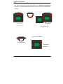
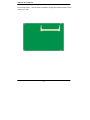
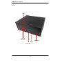
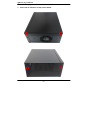
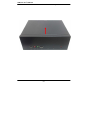
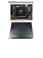
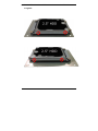
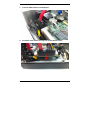
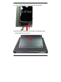
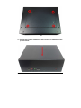
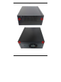
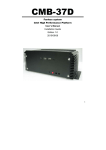
CMB-377
Mini Barebone system
Intel High Performance Platform
Installation Guide
Edition 1.1
2013/06/18
1
Document Content:
z
z
z
Packing List
Product Specification
Hardware Installation
CMB-377 Chassis x 1
(Including LS-377 Motherboard)
DSPD-080-12A 80W AC-DC Adapter x 1
CPU Cooler x 1
PS/2 Keyboard & Mouse Cable x 1
DVI Adapter x1
DVI Cable x1
2
CMB-377
Packing List:
COM PORT cable x 1
CMB-377
DC_IN Power Cable x 1
SATA (7P+15P)Cable x 1
CD Driver x1
3
Hardware Installation:
<Motherboard placement>
JCSEL2
JP1/JP2
JCSEL1
USB
JFRNT IR
COM2
HD Audio
DIO
SYSFAN
Mini Card
CPUFAN
Mini-PCI
DC_OUT
JRTC
SATA
DC_IN
CN_INV
JAT
CD_IN
JVLCD
For Connector
4
For Jumper
SO-DIMM
COM
CRT
PS/2
USB
LAN
5
<Jumper Location & Reference>
Jumper
JRTC
JAT
JP1
JP2
JCSEL1
JCSEL2
Function
CMOS Operating/Clear Setting
Power mode select
COM1 signal mode switch (For Pin-1 & Pin-9)
COM2 signal mode switch (For Pin-1 & Pin-9)
CN_COM2 RS-232 RS422 RS485 Setting / CN_IR IrDA
Setting
Jumper: JAT
Type: onboard 3-pin header
Power Mode
JAT
AT Mode
1-2
ATX Mode
2-3
Default setting:
ATX Mode
3
1
Jumper: JP1 (COM 1)
Type: onboard 6-pin header
Power Mode
JP1
Pin1 with 5V signal
1-2,5-6
Pin9 with 12V signal
3-4,5-6
Default setting:
6
5-6
2
6
1
5
Jumper: JP2 (COM 2)
Type: onboard 6-pin header
Power Mode
JP2
Pin1 with 5V signal
1-2,5-6
Pin9 with 12V signal
3-4,5-6
Default setting:
5-6
2
6
1
5
<Setting RS-232, RS-422, RS-485 & IrDA >
Function
JCSEL1
JCSEL2
2
8
2
12
1
7
1
11
2
8
2
12
1
7
1
11
2
8
2
12
1
7
1
11
2
8
2
12
1
7
1
11
IrDA
RS-422
RS-485
RS-232
7
<Internal Connectors>
Connector
CPU
SO-DIMM
SATA1/2
DC_IN
CN_AUDIO
CD_IN
CN_DIO
CN_USB 1/2
CPUFAN
SYSFAN
CN_LVDS
CN_INV
CN_IR
JFRNT
Mini-PCI
Mini-PCIE
CN_COM2
JAT
Function
Socket rPGA989 for PGA988 CPU
204 -pin DDR3 SO-DIMM socket
7-pin Serial ATA connector
DC 9~24V input connector
5 x 2-pin audio connector
4-pin CD-ROM audio input connector
6 x 2-pin digital I/O connector
5 x 2-pin USB connector
4-pin CPU cooler fan connector
3-pin system cooler fan connector
20 x 2-pin LVDS connector
5-pin LCD inverter connector
5-pin IrDA connector
10-pin front panel switch/indicator
connector
124-pin Mini-PCI socket Type IIIA
52-pin Mini-PCIE socket
9-pin RS422/485/232
Power mode select
Remark
<External Connectors>
Connector
RJ45
COM1 + CRT
PS/2
USB
8
Function
RJ45 LAN connector
COM1 Connect DB15 and analog VGA connector
PS/2 keyboard and mouse connector
2 x USB
Remark
CMB-377 User’s Manual
<CPU and Memory Setup>
The board comes with the socket rPGA-988A for Intel Arrandale and Clarkfield
Processor, Intel® Smart 8MB Cache. Please follow the instruction to install the CPU
properly.
Unlock way
Check point
1. Use the flat-type
screw drive to unlock
2. Follow the pin
4. CPU socket has 989 pins
3. Lock the socket
Socket-M CPU
Check point
-9 -
CMB-377 User’s Manual
2.4.2 <Memory Setup>
The board provides 1 x 204-pin DDR3 SO-DIMM to support 800/1066MHz DDR3 memory
module up to 4GB.
-10-
CMB-377 User’s Manual
I/O panel:
Front:
USB
Line-Out
Mic Phone
Power Button
HD LED
Power LED
-11-
CMB-377 User’s Manual
Rear panel:
DVI
COM1
VGA
-12-
CMB-377 User’s Manual
Chassis Setup procedure:
1. Screw off as indication of the picture below.
-13-
CMB-377 User’s Manual
2. Push the Chassis shield towards the back then open it.
-14-
CMB-377 User’s Manual
3. Turn the CPU cooler screws and then refer the page.9 to install the
CPU.(After installing CPU, please turn the CPU FAN screws to tighten.)
4. Screw off as indication of the picture below.
-15-
5. Insert the DDRII SO-DIMM module into the socket at 45 degree.
Press down the module with a click sound.
16
6. Put on HDD driver into HDD holder then turn the HDD drive screws
to tighten.
17
7. Connect SATA cable to motherboard.
8. Put SATA cable holder through the motherboard holder.
18
9. Connect SATA cable from motherboard to the HD drive.
10. Put the Chassis shield back and screw on as indication of the
picture below Turn the screws.
19
11. Put the top Chassis shield back and screw on as indication of the
picture below.
20
12. Screw on as indication of the picture below.
21
13. Finish
22
Contact Information
Any advice or comment about our products and service, or
anything we can help you please don’t hesitate to contact with
us. We will do our best to support you for your products,
projects and business
Taiwan Commate Computer Inc.
Address
19F, No. 94, Sec. 1, Xintai 5th Rd., Xizhi Dist
New Taipei City, Taiwan
TEL
+886-2-26963909
FAX
+886-2-26963911
Website
E-Mail
Facebook
Twitter
TUhttp://www.commell.com.twUT
[email protected] (General Information)
[email protected] (Technical Support)
https://www.facebook.com/pages/Taiwan-Commate-Computer-Inc/547993955271899
https://twitter.com/Taiwan_Commate
Commell is a brand name of Taiwan Commate Computer Inc.
23