1
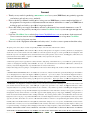
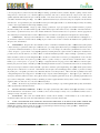
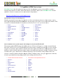
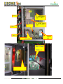
www.CheckMateLasers.com
User Manual
(CheckMate Laser systems)
V1.2
P.O. Box 27116, Las Vegas, NV 89126
www.CheckMateLasers.com
Forward
☆ Thank you very much for purchasing a CheckMate Lasers laser system (XM8 Laser),, we genuinely appreciate
your business and welcome you to our family.
☆ Please read this User Manual carefully prior to using your new XM8 Laser, to ensure complete familiarity of
☆
☆
☆
the equipment. It is imperative to fully understand the information outlined
o
here to ensure your XM8 Laser is
working properly and safely to provide for long term production.
Please shut off the power supply immedi
immediately and refer to this manual if any unusual circumstance occurs.
occurs If
you can’t resolve
solve the problem yourself, please contact CheckMate Lasers or your local agent through email
or phone.
Login into CheckMate Lasers website ((http://www.CheckMateLasers.com) at any time to obtain current and
correct contact information immediately, so you may obtain new
ew information or help from CheckMate
Lasers or your local agent at any time
time.
Please refer to the “Equipment maintenance and safe
safety notice”, in order to ensure operator and machine safety.
TERMS & CONDITIONS
The placing of this order by Buyer constitutes acceptance by the Buyer of the terms and conditions herein contained.
1. PURCHASE OF EQUIPMENT. Seller shall sell to Buyer, and Buyer shall purchase from Supplier for the Price provided above, the Equipment
described above in accordance with the terms and conditions set forth in this Agreement. For purposes of this Agreement, the term "Equipment" shall
include all components of the Equipment, all associated software licensed by Seller pursuant tto
o Section 2 hereof, and all upgrades, enhancements, and
replacements thereof made available, or required to be made available, to Buyer pursuant to this Agreement.
2. LICENSE OF RELATED SOFTWARE.
nonexclusive, fully paid-up,
up, transferable license to possess and use the operational computer
A.Seller hereby grants to Buyer a perpetual, irrevocable, nonexcl
software for the Equipment, including, without limitation, the object code embodiment thereof and all related documentation (collectively,
(
the
Software), solely with the Equipment and to reproduce the Software in connection with such use.
B. Buyer acknowledges that it is acquiring no ownership interest in the Software and that all right, title, and interest in and to the Software remain with
Seller.
3. INSTALLATION AND TRAINING: Prior to the delivery date set forth above, if Buyer and Seller have agreed, Buyer shall prepare the installation
site for the Equipment in accordance with Supplier's installation specifications. Upon notice by Buyer of the arrival of the Equipment at Buyer’s
facility, Seller shall install the Equipment in a timely manner and in accordance with Seller’s installation specifications. In addition, Seller will provide
Buyer with reasonable product and user training as per the quotation accepted by Buyer. Buyer
yer agrees that no one will use the Equipment who has
not been trained and who does not use the required safety equipment and safety practices outlined during the training.
4. WARRANTY:
The Equipment is warranted to Buyer to be free from defects in material and workmanship for a period of twelve months for all
parts and labor (less laser tube and optics).. Seller will repair or replace at its option and no cost to Buyer, any Equipment delivered to Seller's
designated facility in a non-operating
operating condition pursuant to the above warranties. Buyer shall be responsible for determining that the Equipment is in
a non-operating
operating condition upon receipt and will identify the suspected malfunction to Seller. The Seller’s warranty does not apply to performance of
the Equipment caused by abrasive materials,
rials, corrosion due to aggressive fluids, lightning, improper voltage supply, mishandling or misapplication in a
manner inconsistent with that identified in Seller's catalogs and literature. Any warranty granted by Seller to the Buyer shall
sha be deemed void if the
Equipment is used for any purpose not permitted hereunder. In the event that the Equipment is altered or repaired by the Buye
Buyer without prior written
approval by the Seller, all warranties are void. In no event shall Seller be liable for collateral or consequential damages. In addition, the Buyer shall
indemnify Seller and hold Seller harmless from and against any and all claims, damages, losses, costs, expenses, and other liability
li
of whatever nature
that Seller suffers or incurs by reason of any such
ch unintended use. This warranty is made in lieu of any warranty expressed, implied, or statutory; and
no agreement extending or modifying it will be binding upon Seller unless in writing and signed by a duly authorized officer.
EXCEPT FOR THE
EXPRESS WARRANTIES STATED ABOVE, LECME,
LECME, INC. DISCLAIMS ALL WARRANTIES ON PRODUCTS INCLUDING ALL IMPLIED
WARRANTIES OF MERCHANTABILITY AND FITNESS AND THE STATED WARRANTIES ARE IN LIEU OF ALL OBLIGATIONS OR
P.O. Box 27116, Las Vegas, NV 89126
www.CheckMateLasers.com
LIABILITIES ON THE PART OF LECME,, INC. FOR DAMAGES, INCLUDING BUT NOT LIMITED TO SPECIAL, INDIRECT OR
CONSEQUENTIAL DAMAGES, INCLUDING BUT NOT LIMITED TO SPECIAL, INDIRECT OR CONSEQUENTIAL DAMAGES ARISING
OUT OF OR IN CONNECTION WITH THE USE OR PERFORMANCE OF THE PRODUCTS.
5. INDEMNITY: Buyer shall indemnify and save the
he Seller harmless from any and all claims by, for, or against the Seller or Buyer as a result of injury
or damage to Buyer, Buyer's employees, or other persons caused by the equipment during the course of its use herein sold by the
t Seller to the Buyer,
unless
less the injury or damages is as result of negligent manufacture or otherwise.
6. GENERAL PROVISIONS: This contract is made, governed by, and shall be construed in accordance with the laws of the State of Nevada. Seller
and Buyer hereby consent to the jurisdiction of the courts of Nevada or of federal courts located in Nevada with respect to any dispute, controversy or
other matter relating to or arising out of this order. This contract is non
non-assignable, and any attempt to assign any right, duties or obligations under this
contract will be void, except in the case of a change in ownership, contract will insure to present owner. All rights and remedies
re
of either party,
whether evidenced hereby or by any other contract, instrument oorr paper, shall be cumulative and may be evidenced hereby or by any other contract,
instrument or paper, shall be cumulative and may be exercised singularly or concurrently. In the event either party shall, on
o any occasion, fail to
perform any term of this contract, and the other party shall not enforce that term, failure to enforce on that occasion shall not prevent enforcement on
any other occasion.
7. NOTICES:
All notices, requests, consents, and other communications required, or permitted hereunder shall be in writing and shall be mailed by
registered or certified mail, postage prepaid, or transmitted by Telex, TXW, or Facsimile to addresses set forth below, addresses
addre
subject to change by
written notice.
8. ENTIRE AGREEMENT: This Agreement constitutes the en
entire
tire Agreement of parties with reference to the subject matter hereof.
9. SHIPMENT AND PASSAGE OF TITLE: Shipment will be made F.O.B. Point of Origin.
In the absence of specific shipping instruct
instructions,
method of shipment will be determined by the Seller. In all cases, Seller's responsibility (except as stated in its warranty) cease and risk of loss shall
pass upon delivery of the material to the carrier, irrespective of the method of shipment and method of payment for shipment.
10.
SECURITY INTEREST:
Buyer hereby grants to seller a first priority lien and purchase money security interest in the Equipment purchased
hereunder and in all subsequently purchased Equipment, and any and all components, material, systems and sub
sub-systems
systems incorporated therein, togethe
together
with all operating and maintenance manuals and other documents required by this Agreement, and all moneys, securities and oth
other property resulting
from the sale, pledge or other disposition of the same. Buyer will keep the Equipment free from any and all adverse liens, security interests and
encumbrances. Buyer hereby agrees to execute any and all promissory notes, UCC
UCC-1
1 Financing Statements and other documents, and pay any and all
fees, taxes or other costs as necessary to allow the Seller to perfect its interest in the Equipment Seller agrees that upon full satisfaction of the purchase
price and all related charges for the Equipment, Seller shall execute UCC termination statements as necessary.
11.
DELIVERY:
Seller will endeavor to meet delivery schedules, but in no case shall Seller incur any liability, consequential or otherwise, for
any delays or failure to deliver as the result of any cause beyond its reasonable control, including, without limiting the generality
ge
of the foregoing, acts
of God, of a publicc enemy, or of the Buyer; or disputes, accidents, transportation conditions, government actions of any kind, inability to secure
sec
adequate material or labor, or any cause similar or dissimilar to the foregoing. Quoted delivery dates are Seller's best estimate,
est
on the basis of current
schedules. In no event shall Seller be liable for special or consequential damages resulting from failure to meet requested delivery schedules.
Incremental or additional costs incurred by Seller as a result of Buyer's alterna
alternation
tion of the delivery schedule, whether or not such alteration constitutes a
change under Paragraph 11 hereof, will be borne by Buyer.
Buyer agrees to inspect the equipment at Seller's designated facility prior to shipment, at Buyer's expense, for the pur
purpose
pose of confirming the operating
condition, functions, features, and performance of the equipment. If buyer fails to inspect the equipment prior to shipment to Buyer's designated facility,
Buyer relinquishes the right to refuse acceptance of and to make ppayment
ayment for the equipment for reasons relating to the equipment's functions, features
and/or performance.
12.
TERMINATION AND BREACH: This contract may be terminated by Buyer only when approved in writing by Seller.
In the event of
termination, Seller will take
ke immediate steps to mitigate termination costs to Buyer, but Buyer shall reimburse Seller for the cost of labor, overhead,
and material costs and other commitments made by seller in reliance upon this order. Insolvency of the Buyer, the filing of a petition in bankruptcy or
the commencement of any insolvency or receivership proceeding shall be deemed a termination of the Buyer. Notwithstanding an
any provision to the
contrary herein, if Seller shall at any time have grounds for insecurity with respect to Bu
Buyer's
yer's performance hereunder and buyer shall fail to provide
adequate assurance of due performance within thirty (30) days after the mailing to it by Seller of a demand for such assurance,
assuranc then Seller may
consider this contract repudiated and shall have all the rights to a Seller for such repudiation under the General laws of Nevada.
Nevada
P.O. Box 27116, Las Vegas, NV 89126
www.CheckMateLasers.com
13.
CHANGES: No change shall be made in descriptions and specifications relating to this order without the written consent of Seller.
Se
Subject
to the foregoing,
g, Buyer, by written order, may make changes in drawings, specifications, delivery schedules, shipment or packing of articles if such
changes increase or decrease the cost of, or the time required for performance of this order, or otherwise affects any of the provisions of this order, an
equitable adjustment shall be made in the price or delivery schedule, or both, and in such other provisions of this order as may be so affected, and the
order shall be modified in writing accordingly.
Any claim for adjustm
adjustment
ent hereunder may be asserted at any time prior to shipment of the last item due
under this order. It is agreed that the prices stated herein are based upon normal supplied and labor costs and that any req
request of Buyer necessitating
overtime or other expense
nse shall be deemed a change under this provision.
14.
REPRODUCTION RIGHTS: Designs, processes, drawings, specifications, reports, photographs, data and other technical or proprietary
proprie
information relating to this order shall remain the property of Seller and Buyer agrees that it will not use any of such items or information therein for
the production or procurement from any other source of articles furnished in connection with this order, nor reproduce or otherwise
oth
appropriate the
same without the prior written
n authorization of Seller or until such items or information become publicly known through a source other than Buyer.
15.
CONFIDENTIAL: Buyer agrees that it will not disclose or make available to any third party any of the items referred to in Paragraph
Pa
14, or
any information contained in such items without obtaining the prior written consent of Seller or until such information becomes
becom publicly known,
through a source other than Buyer.
16.
INFRINGEMENT: Except insofar as this order calls for articles or materials not manufactured by Seller, or manufactured by Seller pursuant
to Buyer's drawings or specifications, Seller agrees to defend any suit or proceedings against Buyer based upon an infringement
infringeme claim that any article
or part thereof manufactured hereunder, by
y reason of its manufacture, sale or use, infringes any United States patent which was issued at date of
contract, and agrees to pay the amount of any judgment against Buyer resulting therefrom, together with all costs and expenses
expense incident thereof,
provided
ed however, that such claim does not relate to articles or materials manufactured pursuant to Buyer's drawings or specifications,
specificati
provided,
further, that Seller is notified of such an infringement claim or the threat of commencement of such suit or proceed
proceeding
ing within two weeks of the time
Buyer received notice thereof and is given an opportunity, with the cooperation of Buyer, to conduct the defense or settlement
settlemen thereof. Seller's
liability to pay or incur expenses or to pay any costs, damages or judgments under the foregoing provision shall be limited to an amount equal to
Purchase price paid for the articles or material upon which such infringement claim is based less a reasonable allowance for the use and depreciation.
Seller reserves the right to substitute
ute for articles, materials, or parts thereof, which in its opinion might infringe, other equally suitable products without
altering the other conditions before or after sale. Seller shall also have the right to take back infringing articles, mater
materials, or parts thereof, refuting
the purchase price or an equitable portion thereof less a reasonable allowance of use and depreciation. Seller assumes no re
responsibility for the actual
or alleged infringement of any foreign patent or other matter except as expre
expressly
ssly stated in this Paragraph 17. Buyer agrees to pay to Seller all costs
and expenses incurred by Seller in its defense, and to pay the amount of any judgment against Seller, in any suit or proceedi
proceeding against Seller based
upon a claim of infringement, resulting
sulting from Buyer's combining any articles supplied hereunder with any articles or device not manufactured or
supplied by Seller or from the sale or use of any such combination by Buyer.
17.
TAXES: The amount of any present future sales, use, or similar taxe
taxes,
s, and import or export tariffs applicable to the products sold hereunder,
shall be payable by Buyer when and as incurred.
18.
SELLER'S ADDITIONAL REMEDIES: In addition to the rights specified herein, Seller shall have all the rights and remedies of a Seller
under the General Laws of Nevada and no waiver of or failure to enforce and as such right or remedy on one occasion shall be deemed a waiver of
such right or remedy on any future occasion.
19.
SEVERABILITY:
These terms and conditions sha
shall
ll be severable and the invalidity or unenforceability of any of them under any
circumstances shall not affect those terms and conditions which are not held to be invalid or unenforceable.
20.
BUYER ACKNOWLEDGES THAT SELLER HAS THOROUGHLY EXPLAINED TO BUYER HO
HOW
W TO SAFELY OPERATE THE
EQUIPMENT AND EXPLAINED ALL POTENTIAL HAZARDS THAT COULD RESULT FROM THE IMPROPER USE OF THE EQUIPMENT.
NOTICE: The equipment sold hereby should only be used by properly trained personnel who follow proper safety precautions. Fa
Familiarize all
persons with safety practices before they use the equipment.
P.O. Box 27116, Las Vegas, NV 89126
www.CheckMateLasers.com
1. Introduction
1.1 Safety introduction:
The XM8 Laser described here is a Class I laser device (Class III with red diode pointer) and is considered
dangerous if not operated properly.
• The laser beam can instantly ignite cloth
cloth, wood, paper, plastics, and many
ny other common items and can
seriously burn flesh, including eyes.
yes.
• Care must be taken to avoid serious injury and/or blindness.
b
• Always operate this and any other high power laser
lasers in an environment free of flammable materials, children,
pets, spectators, etc.
• Always use infrared eye protection ggoggles when operating this laser. Failure
ailure to due so may result in
permanent blindness.
• The XM8 Laser uses lethal high voltages.
oltages. Care must be taken when working with the high voltage. Failure to
do so may result in serious injury
njury or death.
• Builder and/or user assume all risks!
isks! By assembling this laser kit or by using the information contained in
this manual to build, repair, or otherwise work with lasers or other high
high voltage devices of any kind you do
so at your own risk.
1.2 Additional items require for XM8 Laser setup
You will need the following items in order to complete setup of the XM8 Laser:
• One large water bucket with a capacity of 5 gallons of distilled water (water
water from which all gases and
minerals have been removed) will be used for cooling of the laser
aser tube if water circulator/chiller was not
purchased.
• A single strand of copper wire at 12 gauge (.081” or 2mm diameter), a bit thicker than standard wire coat
hanger, will be required for grounding.
1.3 Technical specifications
This manual uses the CheckMate Lasers Queen laser system as the example; the XM8 Laser is equipped with a CO2
glass laser tube. The high-power laser beam is created by the laser tube, under high pressure, which will first pass
through a series of reflective mirrors prior to passing through the focal lens which is focused onto the surface of the
material which vaporizes that material in order to raster engrave and/or vector cut the material successfully.
•
•
•
•
High grade and exact mechanics are
re used to guarantee the precision and long time, stable production
production.
Exhaust-fans, air-exhaust
exhaust pipe, and track exhaust are used to ventilate away the fumes and dust created by
the laser beams vaporization process. Effectively minimizing
minimi
smoke and debris on the optics. The
ventilation system allows the laser system to operate cleanly, safely and properly.
Air assist is the hose plumbing from outside the laser system to the laser beam output location. This
addresses three (3) key laser beam issues:
o Cleanliness: Keeps the area be laser engraved or cut clean of debris and smoke
o Airborne: Gets the debris and smoke airborne so the ventilations system can expel outdoors
o Flammage: Minimizes to nearly eliminates flammage that is inherent when cutting materials
A constant clean electrical power current ensures quality engraving and/or cutting without any fluctuation in
beam quality output.
P.O. Box 27116, Las Vegas, NV 89126
www.CheckMateLasers.com
2. Capabilities of XM8 Laser systems
CheckMate Lasers has wide applications in many fields, the XM8 Laser you havee chosen will be essential to
targeting many materials, products, markets and industry opportunities.
opportunities Refer to the CheckMate Lasers Forums
regularly for articles to expand your laser system business opportunities:
http://www.checkmatelasers.com/index.php/forums/
What materials can be processed by CO2 laser?
Virtually any materials except unprocessed metals (see below)) and substances that are too heat sensitive, such as
foam. Other than that the materials the XM8 Laser can raster engrave into and/or vector cut are nearly limitless. Here
is a brief list of materials that have been proven to work well (you
(
may come up with many more).
more
•
Acrylic
•
Glass
•
Painted Metals
•
Anodized Aluminum
•
Kevlar
•
Plastics
•
Carbide
•
Laminated Plastics
•
Polycarbonate
•
Ceramic Substrates
•
Leather
•
Polyester
•
Cloth
•
Marble
•
Pressboard
•
Coated Metals
•
Masonite
•
Rubber
•
Composites
•
Matte Board
•
Silicon
•
Delrin
•
Melamine
•
Stone
•
Fabrics
•
Mylar
•
Styrene
•
Fiberglass
•
Nylon
•
Veneer
•
Foam
•
Paper
•
Wood
Can CheckMate Laser systems engrave or cut unprocessed (non-anodized)
(non
metal?
Unfortunately without HIGH wattage units (400+ watts) no CO2 laser will engrave or cut into raw metal directly
unassisted.. CO2 lasers use a wave frequency that allows the lasering of virtually any material (see above) with the
exception of raw metals. Only anodized or coated metal can be engraved by CO2 lasers. Although,
Although there is metal
marking a solution available that when used according to the manufacturer guidelines generates a chemical reaction
crystallizes their “paste” which creates solid black engraving on un
un-coated
coated metals. This procedure when done
correctly is extremely durable and under testing ha
has withstood military testing, outer space applications, lubricants,
salt water spray, high heat testing, high pressure water washing and abrasion tests.
•
To date marks have been made on:
•
The solution is also expected to work on:
•
Aluminum
•
Carbide
•
Brass
•
Gold
•
Chromed Steel
•
Niobium
•
Copper
•
Palladium
•
Lead-coated Steel
•
Pewter
•
Stainless Steel
•
Platinum
•
Tin
•
Silver
•
Titanium
•
Tantalum
•
Tungsten Carbide
P.O. Box 27116, Las Vegas, NV 89126
www.CheckMateLasers.com
3. Components of CheckMate Lasers
3.1 Components of the XM8 Laser
Laser cabinet
cover/lid
X stepper motor
Safety Switch
The
second
mirror
The
third
mirror
The
Focus
lens
Operation
Control Panel
Power
Switch
Panel
X
Work table
Y
Y
X
P.O. Box 27116, Las Vegas, NV 89126
www.CheckMateLasers.com
The laser tube
The
First
mirror
Laser tube
Y
adjustment
Y stepper
per motor
Exhaust out
S
Sockets
Power wire
Ground
Air intake
Chiller
Socket
P.O. Box 27116, Las Vegas, NV 89126
www.CheckMateLasers.com
X Drive
36V switch
power
supply for Drive
switch power
supply control PCB
24V
Relay
Y Drive
Z Drive
Main Switch:
air switch
9V transformer for light
Main Control
PCB Board
Laser Power Supply
P.O. Box 27116, Las Vegas, NV 89126
www.CheckMateLasers.com
Auto or Manual
engrave operation
Emergency Switch
Panic Button
• When
hen the red light is
off, the laser tube will fire
as all doors
door are closed.
• When
hen the red light is on,
laser tube will NOT fire,
regardless if the doors are
opened or closed.
Following are steps required to install and setup the XM8 Laser
:
Install the laser tube and ensure the distilled water is circulating freely through the laser tube, after the wire ties
have been removed, proceed as follows:
1. Turn on Air Switch (located within the side door)
2. Turn on Master Power (located on front of XM8 Laser)
3. Turn on Drive Power (located on front of XM8 Laser)
4. Turn on Laser Power (located
ed on front of XM8 Laser)
5. Turn on Laser Switch (located on the control panel)
panel
6. Conduct beam alignment procedures
P.O. Box 27116, Las Vegas, NV 89126
www.CheckMateLasers.com
4. Installation and Setup
4.1 Installation of the XM8 Laser
4.1.1 Working environment
Note: Although XM8 Laser have been designed to be user serviceable, we recommend only
o
qualified or trained
personnel be authorized to install, upgrade or repair the XM8 Laser!
1. The XM8 Laser must be located in the dry environment. Abnormal operation will occur if wet, which could
include short circuit of electronic component
components, high-voltage discharge, etc. moreover,
oreover, the moisture
environment will cause metal components to degrade and rust.
2. The XM8 Laser must be in a clean, dust, dirt free environment
environment. Excessive dust will pollute the optics
optic (lens
and mirrors) and shorten their
ir lifespan, in addition to increase the speed of abrasion of all mechanical parts.
3. Working condition
a. Surrounding temperature 10—
—30°C relative humidity <70%
b. Power supply single phase: 100-120V/200-240V
1
50Hz 1.6KW
c. The XM8 Laser should be well ggrounded, with a grounding resistance less than 4Ω.
4
4.1.2 Unpacking of XM8 Laser
Open the plywood box to remove the accessories and check them according to the provided accessory checklist.
Remove the plastic wrap covering XM8 Laser. Check for any damage as a result of shipment.
Attention!
If damage is discovered during installation, immediately take photographs and NOTIFY
delivery/trucking/shipping company,
ompany, then inform CheckMate Lasers.
Remove
emove Wire Tie
P.O. Box 27116, Las Vegas, NV 89126
www.CheckMateLasers.com
4.1.3 Location of the machine
The XM8 Laser should be placed on a flat surface near the desired outdoor ventilation location (window, door, wall
outlet, etc.) then adjust the four feet to lift the XM8 Laser off of the four wheels for stability.
Adjust feet to secure
XM8 Laser off wheels
Adjust the height of the machine with a wrench, and tighten the nut.
4.1.4 Grounding
A single strand of copper wire at 12 gauge ((.081” or 2mm diameter), a bit thicker than standard wire coat
hanger, will be required for grounding.
Fasten one side of the wire to the designated connector (PE),
(PE) and the other side to a grounded source.
4.1.5 Connection with the general power supply.
Insert power line into the INPUT at the back of the machine,
machine while connecting the wiring to the switch block.
P.O. Box 27116, Las Vegas, NV 89126
www.CheckMateLasers.com
4.1.6a Installation of the water pump accessory
1. Connect water pump to the XM8 Laser.
2. Place the pump into the bucket
3. Insert the power
ower wire into the main engine
4. Connect the water outlet with the water inlet of the machine
5. Insert
nsert the water outlet of the machine into the rubber tube
6. Finally place the rubber tube into the bucket.
4.1.6b Installation of the water circulator/chiller
circulator/
Attention!
Do not plug into 220v socket if unit is 110v or the unit will be permanently damaged.
1.
2.
3.
4.
Remove the water inlet cover, located on top of the circulator/chiller.
Pour distilled water into the water tank until full.
Connect the water outlet of the chiller to the water inlet of the XM8 Laser
Connect the water inlet of the unit to the water outlet of the XM8
P.O. Box 27116, Las Vegas, NV 89126
www.CheckMateLasers.com
4.1.7 Installation of the air pump/compressor
1. Insert the power line of the air pump into the XM8 Laser
2. Connect the rubber tube of pump/compressor air outlet with the air inlet of the XM8 Laser
4.1.8 Installation of the smoke exhaust fan
1. Connect the air inlet of the exhaust fan with exhaust port of the XM8 Laser
2. Plug in the power line of the fan.
4.1.9 Installation of the laser tube
1. Remove the screw from the two mounts used for mounting of the laser tube.
2. Place the laser tube on the two bases.
3. Attention! Laser beam output is located on right side
side, position laser output facing mirror #1
4. Secure the laser tube
5. Plug in water inlet and outlet tubes
6. Connect the laser tube power wires.
7. Turn on the power supply of the XM8 Laser
8. The water pump should start pumping water.
a. Ensure there are no bubbless in the laser tube (check in 1+ minutes)
b. Rotate the laser tube to remove any bubbles.
c. Attention! Water inlet of the laser tube should be lower than the water outlet
9. Insert the power line of the laser power supply into the control box.
4.1.10 Detections
Turn on the Master Power key, the Drive Power, then Laser Power of the XM8 Laser
1. If the X, Y are not in home position, lens assembly will move back to its home origin
2. If the X, Y stays in original position
position, and you cannot move lens assembly manually in any direction this
indicates that the drive
ive system of the XM8 Laser is operating properly
3. Press ‘test’ button, if the XM8 Laser operates properly, the amperage meter hand indicator will move
P.O. Box 27116, Las Vegas, NV 89126
www.CheckMateLasers.com
4.2. Installation of the XM8 Laser USB cable
Your personal computer (PC) will indicate XM8 Laser connection with “finding new hardware” or similar message,
dependent upon operating system, on the PC.
PC
4.3 Detection of software
Open the software; press each button on the control panel of XM8 Laser to ensure proper operation.
4.4 Beam Alignment of the laser beam path
4.4.1 The laser beam optical path reference diagram
1.
2.
3.
4.
5.
6.
7.
Laser tube
The first reflective mirror
The second reflective mirror
The third reflective mirror
Focus lens
Object being laser engraved/cut
Working platform
Proper laser beam alignment is essential to the proper operation of the XM8 Laser system. The complete system is
made up of the laser tube, three reflective mirrors, one focusing lens and related adjustment screws. These are the
main beam alignment items of the XM8 Laser.
Laser The laser beam path has a direct relationship to the engraving and
cutting quality, therefore be patient and meticulous when adjusting the laser beam alignment path.
Attention!
Ensure the water pump/circulator/chiller is operating and circulating the distilled water prior to operating
XM8 Laser, otherwise serious damage could occur to the laser tube.
P.O. Box 27116, Las Vegas, NV 89126
www.CheckMateLasers.com
4.4.2 Adjustment of the first reflecting lens
1. Place a post-it or masking tape over reflective mirror #2
2. Move the lens assembly to upper left corner of the machine (X1Y1)
3. Press the “test” button (on
on control panel
panel) to fire the laser tube to burn a dot into your test material
4. Then move the laser head to the lower left corner of the machine (X1Y2) to create another dot
5. Use the adjustment screws of the first reflective
reflect lens to move dot burn location
6. Repeat procedure until both dots in X1Y1 & X1Y2 position line up
4.4.3 Adjustment of the second reflecting lens
1. Place a post-it
it or masking tape over reflective mirror #3
2. Move the lens assembly to lower left corner of the machine (X1Y2)
3. Press “test” button to fire the laser tube to burn a dot into your test piece
4. Then move the laser head to the lower right corner of the machine (X2Y2) to create another dot
5. Use the adjustment screws of the second reflective lens to move dot burn location
6. Repeat procedure untill both dots in X1Y2 & X2
X2Y2 position line up
4.4.4 Adjustment of the laser beam center location
Finally, ensure that the laser beam is in the center of the indication of the laser cente
center.
1. If it was not in the center, adjust the laser tube position
2. The second reflective mirror is used to dial in the laser beam to the center location.
3. The laser tube “adjustment” can adjust the location of the laser beam up or down
4. Use the second reflective mirror mount to adjust the location of laser “front” and “back”
Adjustment
Adjustment
P.O. Box 27116, Las Vegas, NV 89126
www.CheckMateLasers.com
P.O. Box 27116, Las Vegas, NV 89126
www.CheckMateLasers.com
If the laser beam alignment path is adjusted properly, the laser beam will be in the center of mirror mount.
4.4.5 Adjustment of the lens focal length
Lens Focal length: 2.5” (63.5±1mm) to the surface of object
1. Focusing lens cap
up
2. Focusing lens (convex/curved side down,, flat side facing up)
3. Air-in nozzle
4. Air-out nozzle
5. Lens cone
6. Focal length measurement
Place material on engraving table; loosen the screw which
w
is on the left of the lens assembly, adjust lens assembly to
2.5” (63.5mm, plus/minus 1mm) distance from material. Then
T
press the “test” button on the control panel and
observe the size of laser beam burn size.. The best distance for focus is the one which makes the smallest dot.
P.O. Box 27116, Las Vegas, NV 89126
www.CheckMateLasers.com
4.4.6 Adjustment of the third reflective
ive mirror
Adjusting
Ensure that the test material placed onto the engraving/cutting table is flat and vertical in reference to the lens
assembly. This will be easily determined through spot testing, if not aligned properly the dot burn will not be round
as expected but odd shaped, adjust the upper third screw to dial in the third reflective mirror.
Attention!
Ensure the water pump/circulator/chiller is operating and circulating the distilled water prior to operating
XM8 Laser, otherwise serious damage could occur to the laser tube.
P.O. Box 27116, Las Vegas, NV 89126
www.CheckMateLasers.com
How to Use the XM8 Laser software
Review XM8 User Manual (Software) for software installation and operation procedures.
How to Use the Rotary Attachment
Connection for
rotary attachment
1.
2.
3.
4.
5.
6.
7.
8.
Place the rotary attachment onto the laser engraving platform
Plug
lug in the connecting cable to the rotary attachment connection point, noted in the image above
The rotary attachment may be placed anywhere on the engraving platform
1) Ensure the rotary attachmentt is horizontally straight
Allow space for the laser head motion movement when beginning or ending ((start
start to finish
finish)
Activate the power switch for the rotary attachment; located next to USB connection
connection; noted in the image below
Enter the figure
ure derived from the “Rotary attachment Move formula” spreadsheet into the Move: field.
Engrave the project.
Done!
Rotary FAQ’s
What is the maximum diameter possible
possible? 3.15” – 7.87” (8-20cm)
2. What it the maximum object length? The
he standard rotary max is 11.811” (30cm) in length.
length
3. Custom lengths: King max = 39.37” (100cm
100cm), Queen max 27.56” (70cm). Rotary takes up 7.87” (20cm).
4. What is the maximum weight supported?
? Maximum supported weight is 11lbs (5kgs)
1.
P.O. Box 27116, Las Vegas, NV 89126
www.CheckMateLasers.com
Rotary
otary clamp
on/off switch
Change “Move” parameter to
set the Y axis rotation speed.
:
Move: The Complex Method
When default parameter Move=36,, make a frame of 10*10cm in software, but you will get a 10cm(X
direction)*L(Y direction) frame on the round surface.
36/10 = Move /L
Move = L * 3.6
Move: The Simple Method:
Use the spreadsheet to quickly determine the Move: figure. (Standard
Standard imperial decimal format
format)
1. Enter design Frame Width & Frame Height
2. Enter Object Diameter (use
use calipers for the utmost accuracy)
accuracy
3. The proper figure (metric) to enter into Move: will be displayed at bottom
P.O. Box 27116, Las Vegas, NV 89126
www.CheckMateLasers.com
6. Safety Consideration and Maintenance
aintenance Procedures
6.1 Safety consideration
1.
2.
3.
4.
5.
6.
7.
8.
9.
10.
11.
12.
13.
14.
15.
16.
17.
18.
19.
20.
It is prohibited to operate the XM8 Laser without proper grounding. The grounding wire of laser power must be
connected with the earth. It should not be connected to building products, such as doors, windows, water pipes,
etc. The wire should be pulled to the outdoor ground or via the outlet plug.
It is required of all parts of the XM8 Laser and user’s computer be grounded to ensure avoidance
avoid
of damage to
XM8 Laser and injuries caused by static electricity.
Operators cannot leave the XM8 Laser unattended while in operation. XM8 Laser must be monitored at all times
in the event of unforeseen circumstance occurring.
Check the submersible pump or water circulation unit to ensure water is out flowing freely upon beginning of
the XM8 Laser operation. It is prohibited to operate the XM8 Laser when water is not flowing from the pump
through the laser tube.
Water container should be a large enough to contain a minimum of 5 gallons (25 kilograms)
kilogram of distilled water
for proper cooling circulation. The water
er temperature should be about 77°F (25°C)
°C) with no contamination.
Circulating water
ater should be changed regularly (three days to one week)
The water in the laser tube should be drained out in extreme cold temperatures, such as winter, in order to avoid
frost and cracking of the glass laser tube.
Due to laser tube and high-pressure
pressure in the XM8 Laser, non-professional /non-qualified workers should
shou not
disassemble the machine without authorization.
Reflective mirrors and focusing lens (Optics) should be wiped with special camera lens paper or medical-use
medical
cotton wetted by lens cleaning fluid. If none is available denatured alcohol or a mixture of aalcohol and ether
(proportion of ether and alcohol
ohol should be 1:1) will suffice. Cleaning of optics should be done at minimum of
once a week, dependent upon material laser engraved/cut this could increase to multiple times per week to daily.
Exhaust/blower fan
an must be turned on while engraving, so as to avoid pollutants on optics.
optics It is prohibited to
place any flammable
lammable and explosive articles close to the XM8 Laser so as to avoid fire or related accidents.
accidents
Air pump/compressor must be in operation when vector cutting. Inherent to typical cut materials is flammage,
air compressor assists in eliminating this dangerous situation. Do not leave XM8 Laser unattended while cutting.
Any reflection objects and materials should not be placed in the XM8 Laser to prevent the laser beam from
reflecting towards a human body or flammable article
article(s) directly.
While the XM8 Laser is in operation , operators should be aware of working conditions (such as whether the
laser beam has been blocked,, air pump/compressor failure, unusual noise, temperature of circulating water, etc.)
at all times. It is the responsibility of operator to constantly monitor the XM8 Laser while in operation!
The crossbeam and lens assembly carriage cannot be moved manually. If possible could imply motor failure.
The XM8 Laser should be placed in a location where there is no interference from or harmful effects
effect of pollution,
strong electricity, strong magnetism, etc.
When the voltage is unstable, it is recommended to use a voltage regulator or line conditioner to provide clean
stable power to the XM8 Laser, otherwise quality engraving/cutting and electronics can be compromised.
Personnel who have not been properly trained in the operation of XM8 Laser should not operate the XM8 Laser.
Do not strike the XM8 Laser keys and buttons
buttons, press lightly to avoid damages to these components
components.
In the event of damage or fire, turn off power to the XM8 Laser immediately!
It is discouraged to operate the XM8 Laser during thunder or lightning storms.
Operators should follow all the above mentioned regulation
regulations carefully. Manufacturer
anufacturer will not take responsibility
for any issues with the XM8 Laser or physical injuries due to negligence on the part of operators.
P.O. Box 27116, Las Vegas, NV 89126
www.CheckMateLasers.com
6.2 Maintenance procedures
6.2.1 Cooling water
The XM8 Laser requires at minimum 5 gallons (25
( kilograms) of distilled water, the temperature of the cooling
water should not exceed 95°F (35°C). Circulating water should be fresh distilled water, containing no impurities. If
excessive vector cutting is the primary application it is recommended to implement a water chiller.
6.2.2 Laser tube
1. There should be no air bubbles in the laser tube. Air bubbles can severely damage the laser tube.
2. It is recommended that the electrical current be below 20MA when the laser tube is in operation.
a. The higher the electrical current, the shorter the laser tube lifespan.
3. When laser tube has ended its lifespan or has been damaged it should be replaced immediately.
Warning! The following steps should only be conducted by properly trained personnel.
Replacement of laser tube should follow these steps to properly uninstall and disassemble the laser tube safely:
1. Stop the running machine prior to disassembly
2. Drain the cooling water from the laser tube
3. Open the back door
4. Remove water tubes connections from both ends of laser
l
tube joint
5. Remove the anode and cathode wiring from the laser tube.
6. Remove the fixed screw
7. Remove the laser tube from the back/left side of the tube (the opposite end of the laser
aser beam output)
carefully and place into a safe location.
Attention! The replaced laser tube is fragile and requires proper disposal.
Adhere to local laws, rules and regulations regarding disposal and/or recycling of glass work. CheckMate
Lasers does not take any responsibility for the replaced glass laser tube.
After removal of the depleted or damaged glass laser tube and replacement with a new laser tube the following
procedure should be implemented.
1. Install the laser tube into the XM8 Laser in the right direction
a. Laser beam output should be pointed to the right toward the first reflective mirror
2. Secure the fasten button.
3. Connect with the water inlet and outlet tubes
4. Connect the anode and cathode power wires to the laser tube.
a. Due to the high voltage with the anode wire, it is highly recommend to utilize insulation
5. Turn on the water pump, and cycle the water for one minute.
6. Adjust the location of the laser tube to remove any air bubbles from the laser tube
7. Close the door
8. Begin testing procedures
P.O. Box 27116, Las Vegas, NV 89126
www.CheckMateLasers.com
6.2.3 Maintenance supplies required:
The following items should be kept in stock for proper maintenance of XM8 Laser
• Denatured Alcohol
• White Lithium Grease
• Lint free clothes
• Cleaning sponge
• 409 or equivalent
• Optic cleaning kit
o q-tips
o lens cleaning cloths
o lens cleaning fluid
6.2.4 Maintenance of the focus lens
The lens can be easily polluted by the dust, smoke and debris created when laser engraving and/or cutting and
should be cleaned after extended use. Att minimum of focus lens should be inspected on a weekly basis.
Focus lens cleaning procedure
1. Loosen the screw on the left and turn down the lower part.
2. Twist off the air assist outlet, and then turn down the nut with the appropriate tool
3. Remove the focus lens
4. Use lens cleaning fluid, denatured alcohol or similar cleaning solution to clean the lens
5. Use denatured alcohol to clean around the lens assembly and inner parts
6. Reinstall the focus lens
7. Attention! The flat surface
ace of the focus should face up, convex side face down
6.2.5 Reflective mirrors cleaning procedure
1. Wrap lens tissue in Q-tip
tip and wet with lens cleaning fluid
2. Lightly wipe mirrors with wet lens tissue gently
Attention:
Aggressively rubbing of mirrors can scratch the surface
surface, rub lightly!
Scratched mirrors will directly affect the laser beam power output
6.2.6 Linear railings cleaning procedure
1. Clean the dirt from the railing with clean soft lint-free
free cloth wetted with denatured alcohol
2. Upon completion spread a thin
in coat of white lithium grease to ensure smooth operation
6.2.7 XM8 Laser cleaning procedure
1. Using a damp cloth, wipe bottom of XM8 Laser chassis
2. If necessary use a vacuum to remove debris, DO NOT use compressor, optics will be compromised
3. Using the 409 or equivalent and cleaning sponge to clean interior and exterior cabinet
4. Acrylic in XM8 Laser lid: DO NOT use glass cleaner, use acrylic cleaner if available, if not available then
plain water and clean, lint-free
free cloths will suffice.
5. Clean the XM8 Laser once a week.
P.O. Box 27116, Las Vegas, NV 89126
www.CheckMateLasers.com
Maintenance and Repair
•
•
•
•
•
•
•
•
•
•
Laser engraving mechanism,, lens assembly and worktable should be kept clean of dust and debris.
Preventative maintenance should be conducted on a regular basis. Weekl
Weeklyy at minimum regardless of use.
Type of material, environment, and operating hours will determine frequency.
X & Y axis railings should be cleaned gently with clean lint-free
free cloths wet with denatured alcohol then
lightly lubricated with white lithium grease re
regularly. Do not allow grease to come in contact with belts
belts.
Clean focusing lens with Q-tip wetted
ted with lens cleaning fluid, denatured alcohol or absolute ethyl alcohol
(chemically pure) once a day at minimum, material, environment, operating hours will determine frequency.
Floating dust on reflective mirrors can be blown away with a mini compressor, or gently wiped off with lens
cleaning cloths.
If mirror coating is damaged due to scratches, worn off, scum buildup, etc. it will influence the depth of
engraving and cutting quality and sho
should be replaced as soon as possible.
XM8 Lasers should be kept dry inside the system at all times. Especially reflective mirrors
mirrors, laser power and
switch power. If moisture has accumulated in XM8 Laser, operator should remove power cable from power
outlet, then completely dry with hairdryer.
If the laser beam alignment shifts when engraving, it should be adjusted as soon as possible.
When troubleshooting XM8 Laser, power cable should be removed from electrical outlet first. It is
discouraged to plug and pull cables and connecting wire
wires inside
nside machine with electricity connected.
Before use, always checkk whether cooling water and external connecting wires are normal. It is prohibited to
operate without
hout cooling water circulation
circulation. The cooling system can prevent the laser tube from overheat
overheating,
cracking, becoming damaged.
Safety At
Attention and Maintenance
I. Safety attention
1. Avoid operating the XM8 Laser without grounded wire connected. The grounding wire for laser power must
be connected to ground, not to a door or window, pump and other establishments, and it must be connected
to the outdoor ground.
2. Operator should
hould check whether water is flowing freely from the water pump when starting the XM8 Laser
each time. CheckMate Lasers strongly prohibits
prohibit operating the XM8 Laser without water circulation.
3. The water container should be large enough to guarantee the circulation of water at 5 gallons (25 kilograms).
4. The water temperature should be at about 77°F (25°C),, change water if the temperature exceeds this degree.
5. Distilled water is highly recommended
recommended, and water should be changed regularly (every
every three days to weekly).
weekly
6. The reflective mirrors and focus lens should be cleaned with professional
al camera lens paper or medical
cotton stick with denatured alcohol
ohol or mixture of alcohol and ether. (the mixing
xing proportion of alcohol and
ether is 1:1) Usually they should be cleaned oonce a week minimum.
7. Always operate ventilation when XM8 Laser is in operation to avoid polluting the optics.
optics
8. Drain laser tube’s water in extreme cold temperatures, to aavoid crack of glass tube during cold weather.
9. Placing dangerous items around machine is discouraged to avoid fire hazards.
10. NEVER operate XM8 Laser unattended, in the event mechanical failure occurs.
occurs
11. There is a laser tube and high pressure parts
part in the XM8 Laser, untrained personnel should be prohibited
from disassembly,, repair and upgrading of XM8 Laser system.
12. Any reflective objects and materials should not be placed in the XM8 Laser to prevent the laser beam from
reflecting towards a human body or flammable article(s)
article directly.
13. XM8 Laser should not be operated without clean electrical power output.
output. A line conditioner, voltage regulator
or transformer may be required to ensure stable, steady electrical power.
P.O. Box 27116, Las Vegas, NV 89126
www.CheckMateLasers.com
14. White lithium
ithium grease should be lightly applied to linear rails regularly.
15. Personnel without proper training should not operate the XM8 Laser.
16. Do not strike the XM8 Laser keys and buttons
buttons, press lightly to avoid damages to these components
components.
17. It is discourage to operate the XM8 Laser during thunder or lightning storms.
II. Maintenance
1. Use of impure, contaminated water for circulation is highly discouraged. Unclean water deeply influences
the laser power and shortens the laser tube lifespan.. The damage of laser tube due to the impure water is not
covered under warranty. CheckMate Lasers advises the use of pure distilled water. Ensure the water is not
less than 5 gallons (25 kilograms), and completely covers the water pump if a water circulator is not present.
2. During laser operation the operator must regularly test the water temperature,
re, once the water become warm
immediately change water (to
o eliminate production interruption simply drain part of the water and refill with
cold water).
3. When adjusting the laser beam output
output, do not exceed 20MA to prevent fast aging of laser tube.
4. Operator must
ust clean the water case, water pump and rubber pipe every three days to weekly minimum
minimum.
5. Operator must clean the lens prior to new work day operations
6. The reflective mirrors should be cleaned carefully, otherwise may require beam alignment
7. Pay close attention to the focal distance each time prior to beginning projects.. If the focal distance is not
exact, engraving and cutting quality will suffer greatly.
8. Operator should clean the working table after each project to ensure smooth operation
9. Operator should clean the XM8 Laser when finish working. It should be done when the power is off, manual
movement of the lens assembly will be possible, but do not force.
10. Every week, operator should clean the linear rails and add a light film of white lithium grease to the rails
11. Every week, operator should clean the outside accessories (fan, air pump, etc.)
Introduction of the XM8 Laser vulnerable parts
1. Laser tube
This machine uses a China-made sealed off type carbon dioxide glass laser tube. Air volume in the glass tube is
fixed, whose service life is approximately 1 year
year. Its service can be roughly
ughly divided into four phases:
1. Phase one: Excellent phase, when laser tube is in steady status. All performances are in the best status.
status
2. Phase two: Steady phase,, when laser tube is in steady status. Under the same current, light intensity is a
little weaker than that in phase one, but is enough to satisfy working dema
demand.
3. Phase three: Decline phase.. After being used for a quite long time, every index of laser tube begins to
decrease. The laser beam intensity becomes weaker. Now, you can increase current and slow down speed to
satisfy requirements for engraving depth.
4. Phase four: Depletion phase. The service
ervice time of laser tube is nearing its end.
It has been determined the laser tube service life can be directly attributed to the operation of the XM8 Laser. The
length of steady phase is the key of laser tube usage. The quality of maintenance directly affects the length of steady
phase. The essentials for proper maintenance are as follows:
1. XM8 Laser working environment must be consistent.. Power voltage must be steady. If voltage fluctuates too
much,, steady power supply should be equipped. The machine must be placed firmly on flat flooring without
P.O. Box 27116, Las Vegas, NV 89126
www.CheckMateLasers.com
2.
3.
4.
5.
6.
great vibration, and XM8 Laser cannot work in a damp environment.
Laser beam output current should be lower than 20mA. In addition, laser beam intensity should be adjusted
to be as low as possible while still satisfying engraving depth and speed.
a. 13~17mA is relatively suitable current range.
Laser tube is a heating element, so the quality and quantity
qu
of circulating water is essential
essential.
a. Quality—distilled
distilled water is essential
essential.
i. Replace circulating water regularly (every three days to one week).
ii. Replacing water is carried out only when XM8 Laser is not in operation.
operation
b. Quantity—Ensure
sure there is enough circulating water 5+ gallons (25+ kilograms).
kilograms
i. Be sure the temperature of circulating water is between 41°F-77°F (5
5°C~25°C)
Under the condition of satisfying working requirement, optimum working method should be used to extend
service life of laser tube as far as possible.
Reflective mirrors and focal lens
a. The surfaces of reflector lens and focusing lens has been polis
polished
hed precisely and plated with a special
layer of thin reflective film. Their surface cleanlines
cleanliness directly affects the reflective
eflective rate and focusing
effect of laser beam,, so they should be cleaned and maintained regularly. Cleaning
Clean
should be strictly
followed by outlined maintenance procedures, which can extend the optics service life.
Water pump and air blower
a. Their maintenance
enance is relatively simple. When XM8 Laser completes projects for the day, the
accessories should be maintained
maintained. Dust must be removed and cleaned regularly so as not to influence
the working effect and service lif
life. Air blower has special requirement, such
h as, not to be operated in
rain or intense sunshine.
Troubleshooting:
Laser tube does not output laser beam during testing.
1. What to check:
a. Is water flowing freely?
b. Has the laser power supply been damaged
damaged?
c. Has the laser tube been damaged?
2. Laser scanning mechanism doesn't work when power switch has been turned on.
a. Check whether the control panel supplies power?
b. Check whether
hether the USB connection of XM8 Laser and PC has issues
c. Check whether the installation of XM8 Software has issues?
3. There is misplacement of engraving and cutting images during operation.
a. Troubleshooting possibilities:
possibilities
i. There
here is external interference; radios, cell phones, speakers, magnets, etc.
ii. XM8 Laser nott grounded properly;
properly check ground wire
iii. Static electricity of environme
environment is to high; use grounding pad/strap
iv. PC hass electrical or software issues; if possible check output from different PC
v. USB cable is problematic; replace to eliminate USB as problem
vi. Engraving
ngraving path has faults;
faults redesign project
4. The depth of engraving on any material is too shallow.
a. Troubleshooting possibilities
possibilities:
i. Laser beam deviates;; check beam alignment
P.O. Box 27116, Las Vegas, NV 89126
www.CheckMateLasers.com
ii. Optic components are polluted or damaged, for example, the plating film
f
of reflective mirrors
is degraded, damaged, scratched, worn off, fallen off; clean or replace
iii. Focusing lens is polluted
polluted; clean or replace
iv. Thee power of laser tube decreases; ensure clean electrical power, check age of tube, replace
Frequently Asked Questions and Solutions
What focal length lens typically ships with each XM8 Laser?
• King … 2.5” (63.5mm)
• Queen …2.5” (63.5mm)
• Rook HS … 2.5” (63.5mm)
• Rook … 1.77” (45mm)
• Bishop … 1.77” (45mm)
• Knight … 1.77” (45mm)
• Pawn … 1.77” (45mm)
• Available for thick acrylic vector
tor cutting
o 3.15” (80mm)
o King, Queen, Rook HS only
What is the beam diameter size
ze of each lens?
• 1.77” (45mm) = .003” (.0762mm)
• 2.5” (63.5mm) = .007” (0.1778mm)
• 3.15” (80mm) = .009” (0.2286mm)
Reason
Solution
Laser power is bad.
Change
hange laser power.
Laser power data wire is bad.
Change
hange laser power data wire.
There is no TTL signal output in control.
Check control signal.
The laser tube is aging.
Change
hange laser tube.
The focus lens is dirty.
Clean the focus len
lens.
The reflective mirror(s) is dirty.
Clean the reflection len
lens.
The laser beam power is not right.
Increase the laser power
There are two cuts
The laser beam is not passing through center of
focus lens,, may be bouncing off lens assembly.
Adjust the third reflective
mirror
When cutting a square, it
becomes parallelogram. A
rectangle is a form of a
parallelogram.
The X, Y guide is not square.
Adjust X, Y guide to square
Issue
XM8 Laser doesn’t
produce laser beam
XM8 Laser can’t cut
completely
P.O. Box 27116, Las Vegas, NV 89126