1
18
CHAPTER.5. OBSERVING
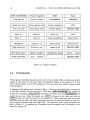
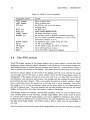
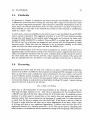
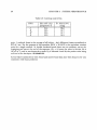
Table 5.1: IRAC-2 User Commands
Command syntax
FILT [name]
LENS [name]
OIT [n]
NOIT [n]
NINT [n]
IDENT [text]
NCOORS [n]
ETYPE [type]
FP [A
FP [posn]
FOC [i]
EXIT
5.3
Action
Move to given filter
Move to given lens
set OIT to n sec or to the closest
possible value
set NOIT to 71
NOT IMPLEMENTED
set image identifier to [text]
set the read mode t.o Double correlated sampling
(n = 2), Triple correlated sampling (11. = 3), or nondestructive readout (n = 4)
set exposure type, Le DK, CAL, FF, Sel
set FP to wavelength A
set FP wheel to pos. IN, OUT, or MASI(
move telescope focus to pos. i
exits the BASIC acquisition program
The PPS system
The PPS display consists of two image displays and a zoom window, several data fields
displaying various detector-related parameters and the status of the current integration,
and several buttons to control the user fuctions; see Figure .5.1,. A three-button mouse is
used to activate the buttons on the display. The three buttons on the mouse are equivalent.
Of the two square regions in the center of the display, the left one is used for the image
and the right one for the noise. A zoom window above the left image display shows an
enlargement of the region around the cursor and, next to it, is a data. field that indicated
the minimum and maximum pixel values, the average and the standard deviation of the
pixel within the zoom window. This is very useful, for instance, to check whether a bright
star is saturated, to see the mean level of the sky, and to aid in focussing. Just below
the image is a 9 x 9 array of numbers, these are the pixel values at the cursor positions
and the 8 adjacent ones. The zoom window and the pixel display exist only for the image
display and are active only when the cursor is inside on the image.
Two display modes are available, denoted OIT and NOIT, which are used to display every
basic readout (OIT) or only the final, average image (NOIT). The current mode is shown
in a button above the left image display, and can be toggled by clicking on that button.
In NOIT mode an RMS frame is computed from the basic integrations and is displayed in
the right-hand image display. The default mode is OIT, in which case the noise display is
not used.
Near the bottom and top left corners of the image display are two pairs of buttons, marked