1
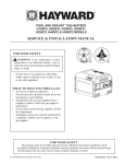
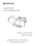
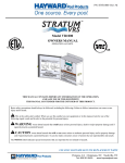
HP13023770 Rev: F
Models: HP20654T, HP20654BT, HP20854T,
HP20854BT and HP21104T
INSTALLATION GUIDE
Important Information to
keep for Service
Model # ________________
Serial # ____________________
Install Date _________________
SAVE THIS INSTALLATION GUIDE
The Hayward HeatPro Heat Pump is listed by ETL as complying with the latest edition of the “UL Standard for Safety for
Heating and Cooling Equipment”, UL1995 and CSA C22.2 No. 236.
All Hayward HeatPro Heat Pumps must be installed in accordance with all applicable National and Local codes. In the absence
of local codes, refer to the latest edition of the National Electric Code (NEC) in the United States and the Canadian Electric
Code (CEC) in Canada
Basic safety precautions should always be followed, including the following: Failure to follow instructions can cause severe
injury and/or death.
This is the safety-alert symbol. When you see this symbol on your equipment or in this manual, look for one of the following
signal words and be alert to the potential for personal injury.
WARNING
warns about hazards that could cause serious personal injury, death or major property damage and if
ignored presents a potential hazard.
CAUTION
warns about hazards that will or can cause minor or moderate personal injury and/or property damage
and if ignored presents a potential hazard. It can also make consumers aware of actions that are unpredictable and unsafe.
The NOTICE label indicates special instructions that are important but not related to hazards.
USE ONLY HAYWARD GENUINE REPLACEMENT PARTS
Pomona, CA Clemmons, NC Nashville, TN
Tel: 908.351.5400
www.haywardpool.com
Page 2 of 20
HEATPRO HEAT PUMP
HP13023770 Rev: F
IMPORTANT SAFETY INSTRUCTIONS
READ AND FOLLOW ALL INSTRUCTIONS IN THIS INSTALLATION
GUIDE AND ON EQUIPMENT.
Before installing or servicing this electrical equipment, turn power supply OFF.
KEEP ALL LABELS IN GOOD CONDITION AND REPLACE IF MISSING OR DAMAGED.
WARNING – To reduce risk of injury, do not permit children to use or climb on the heat pump, pumps or filters. Closely supervise
children at all times. Components such as the filtration system, pumps, and heaters must be positioned to prevent children from using them as a
means of access to the pool.
CAUTION – This heat pump is intended for use on permanently installed swimming pools and may also be used with spas. Do NOT use
with storable pools. A permanently installed pool is constructed in or on the ground or in a building such that it cannot be readily disassembled for
storage. A storable pool is constructed so that it is capable of being readily disassembled for storage and reassembled to its original integrity.
Though this product is designed for outdoor use, it is strongly recommended to protect the electrical components from the weather. Select a welldrained area, one that will not flood when it rains. It requires free circulation of air for cooling. Do not install in a damp or non-ventilated location.
WARNING –Risk of Electric Shock. All electrical wiring MUST be in conformance with all applicable local
codes, regulations and the National Electric Code (NEC). Hazardous voltage can shock, burn, cause death or serious
property damage. Provide a properly located outlet. All electrical wiring MUST be in conformance with applicable local
and national codes and regulations. Before working on this unit, turn off power supply to the heat pump.
WARNING – To reduce the risk of electric shock replace damaged wiring immediately. Locate conduit to
prevent abuse from lawn mowers, hedge trimmers and other equipment.
WARNING – Failure to bond heat pump to pool structure will increase risk for electrocution and could result in injury or death. To reduce
the risk of electric shock, the electrician must comply with installation instructions and must bond the heat pump accordingly. In addition, the
licensed electrician must also conform to local electrical codes for bonding requirements.
Notes to the electrician:
Use a solid copper conductor, size 8 or larger. Run a continuous wire from external bonding lug to reinforcing rod or mesh. Connect a No. 8 AWG
(8.4 mm2) solid copper bonding wire to the grounding lug provided on the heat pump and to all metal parts of swimming pool or spa, and to all
electrical equipment, metal piping (except gas piping), and conduit within 5 ft. (1.5 m) of inside walls of swimming pool or spa. IMPORTANT Reference NEC codes for all wiring standards including, but not limited to, grounding, bonding and other general wiring procedures.
WARNING – Suction Entrapment Hazard.
Suction in suction outlets and/or suction outlet covers which are damaged, broken, cracked, missing, or unsecured can cause
severe injury and/or death due to the following entrapment hazards:
Hair Entrapment- Hair can become entangled in suction outlets.
Limb Entrapment- A limb inserted into an opening of a suction outlet or suction outlet cover that is damaged, broken,
cracked, missing, or not securely attached can result in a mechanical bind or swelling of the limb.
Body Suction Entrapment- A differential pressure applied to a large portion of the body or limbs can result in an entrapment.
Evisceration/ Disembowelment - A vacuum applied directly to the intestines through an unprotected suction outlet sump or suction outlet
cover which is damaged, broken, cracked, missing, or unsecured can result in evisceration (disembowelment).
Mechanical Entrapment- There is potential for jewelry, swimsuit, hair decorations, finger, toe or knuckle to be caught in an opening of a
suction outlet or suction outlet cover resulting in mechanical entrapment.
WARNING - To reduce the risk of entrapment hazards:
o
o
When suction outlets are less than a 18” x 23” [45cm x 58cm] equivalent, a minimum of two functioning suction
outlets per pump must be installed. Suction outlets in the same plane (i.e. floor or wall), must be installed a
minimum of three feet (3’) [1 m] apart, as measured from near point to near point.
Dual suction outlets shall be placed in such locations and distances to avoid “dual blockage” by a user.
USE ONLY HAYWARD GENUINE REPLACEMENT PARTS
Pomona, CA Clemmons, NC Nashville, TN
Tel: 908.351.5400
www.haywardpool.com
Page 3 of 20
o
o
o
o
o
HEATPRO HEAT PUMP
HP13023770 Rev: F
Dual suction fittings shall not be located on seating areas or on the backrest for such seating areas.
The maximum system flow rate shall not exceed the flow rating of any listed (per current revision of ASME/ANSI A112.19.8) suction
outlet cover installed.
Never use the Pool or Spa if any suction outlet component is damaged, broken, cracked, missing, or not securely attached.
Replace damaged, broken, cracked, missing, or not securely attached suction outlet components immediately.
In addition two or more suction outlets per pump installed in accordance with latest APSP (formally NSPI) Standards and CPSC
guidelines, follow all National, State, and Local codes applicable.
WARNING – Never operate or test the circulation system at more than 50 PSI.
WARNING – Failure to remove pressure test plugs and/or plugs used in winterization of the pool/spa from the suction outlets can
result in an increase potential for suction entrapment as described above.
WARNING – Failure to keep suction outlet components clear of debris, such as leaves, dirt, hair, paper and other material can
result in an increase potential for suction entrapment as described above.
WARNING – Suction outlet components have a finite life, the cover/grate should be inspected frequently and replaced at least every
ten years or if found to be damaged, broken, cracked, missing, or not securely attached.
WARNING – All suction and discharge valves MUST be OPEN when starting the circulation system. Failure to do so could result in
severe personal injury and/or property damage. All drains and suction outlets MUST have properly installed covers, securely attached using the
screws supplied with the covers. If screws are lost, order replacement parts from your supplier.
WARNING–Hazardous Pressure. Pool and spa water circulation systems operate under hazardous pressure during
start up, normal operation, and after pump shut off. Stand clear of circulation system equipment during start up. Failure to
follow safety and operation instructions could result in violent separation of the pump housing and cover due to pressure in the
system, which could cause property damage, severe personal injury, or death. Before servicing pool and spa water circulation
system, all system and pump controls must be in off position and filter manual air relief valve must be in open position. Before
starting system pump, all system valves must be set in a position to allow system water to return back to the pool. Do not change
filter control valve position while system pump is running. Before starting system pump, fully open filter manual air relief valve.
Do not close filter manual air relief valve until a steady stream of water (not air or air and water) is discharged.
WARNING–Separation Hazard. Failure to follow safety and operation instructions could result in violent separation
of pump components. Strainer cover must be properly secured to pump housing with strainer cover lock ring. Before servicing
pool and spa circulation system, filter manual air relief valve must be in open position. Do not operate pool and spa circulation
system if a system component is not assembled properly, damaged, or missing. Do not operate pool and spa circulation system
unless filter air relief valve body is in locked position in filter upper body.
WARNING–Fire and burn hazard. Motors operate at high temperatures and if they are not properly isolated from any flammable
structures or foreign debris they can cause fires, which may cause severe personal injury or death. It is also necessary to allow the motor to cool for
at least 20 minutes prior to maintenance to minimize the risk of burns.
WARNING – Failure to install according to defined instructions may result in severe personal injury or death.
WARNING – The following “Safety Rules for Hot Tubs” recommended by the U.S. Consumer Product Safety Commission should be
observed when using the spa.
1. Spa or hot tub water temperatures should never exceed 104°F [40°C]. A temperature of 100°F [38°C] is considered safe for a healthy adult.
Special caution is suggested for young children. Prolonged immersion in hot water can induce hyperthermia.
2. Drinking of alcoholic beverages before or during spa or hot tub use can cause drowsiness, which could lead to unconsciousness and
subsequently result in drowning.
3. Pregnant women beware! Soaking in water above 100°F. [38°C] can cause fetal damage during the first three months of pregnancy (resulting
in the birth of a brain-damaged or deformed child). Pregnant women should adhere to the 100°F. [38°C] maximum rule.
4. Before entering the spa or hot tub, users should check the water temperature with an accurate thermometer; spa or hot tub thermostats may err in
regulating water temperatures by as much as 4°F [2.2°C].
5. Persons taking medications, which induce drowsiness, such as tranquilizers, antihistamines or anticoagulants, should not use spas or hot tubs.
USE ONLY HAYWARD GENUINE REPLACEMENT PARTS
Pomona, CA Clemmons, NC Nashville, TN
Tel: 908.351.5400
www.haywardpool.com
Page 4 of 20
HEATPRO HEAT PUMP
HP13023770 Rev: F
6. If the pool/spa is used for therapy, it should be done with the advice of a physician. Always stir pool/spa water before entering the pool/spa to
mix in any hot surface layer of water that might exceed healthful temperature limits and cause injury. Do not tamper with controls, because
scalding can result if safety controls are not in proper working order.
7. Persons with a medical history of heart disease, circulatory problems, diabetes or blood pressure problems should obtain a physicians advice
before using spas or hot tubs.
8. Hyperthermia occurs when the internal temperature of the body reaches a level several degrees above normal body temperature of 98.6°F.
[37°C]. The symptoms of Hyperthermia include: drowsiness, lethargy, dizziness, fainting, and an increase in the internal temperature of the
body.
The effects of Hyperthermia include:
1.
2.
3.
4.
5.
6.
Unawareness of impending danger.
Failure to perceive heat.
Failure to recognize the need to leave the spa.
Physical inability to exit the spa.
Fetal damage in pregnant women.
Unconsciousness resulting in danger of drowning.
DEFINITIONS:
Suction Outlet – The term Suction Outlet is a fitting, fitting assembly, cover/grate and related components that provide a means for water to exit the
pool and into the pump circulating system.
Inches of Mercury (in Hg) - A unit for measuring pressure below atmospheric (“suction” or “vacuum”) (1.0 inch Hg = .491 PSI)
Main Drain – See Suction Outlet
PSI – An abbreviation for pounds per square inch.
INSTALLATION:
Materials needed for Installation
The following items are needed and supplied by the installer for all heat pump installations.
1.
Plumbing connections:
2 inch PVC pipe Schedule 40 and 2 inch fittings and components as follows:
(3) - 2 inch Isolation Valves
(1) - 2 inch Check Valve
(2) - 2 x 2 x 2 PVC Tee’s
NOTE: Pipe fittings such as reducers, tees, and elbows cause pressure to drop as water flows through them.
Plan the plumbing layout carefully, using as few fittings as possible to connect your heat pump. See plumbing
diagram under the heading “Plumbing Specifications and Layout” for more information.
2.
Level surface for proper draining.
3.
Suitable electrical supply line. See rating plate on the heat pump units for electrical specifications. A
junction box is not needed at the heat pump; connections are made inside the heat pump electrical
compartment. Minimum wire size to be selected per NEC SEC.440.33 based on unit MCA.
4.
Electric disconnect switch that will interrupt all power to the unit. This switch MUST be within line of
sight of the heat pump.
USE ONLY HAYWARD GENUINE REPLACEMENT PARTS
Pomona, CA Clemmons, NC Nashville, TN
Tel: 908.351.5400
www.haywardpool.com
Page 5 of 20
HEATPRO HEAT PUMP
HP13023770 Rev: F
Hayward HeatPro Heat Pump Dimensions
MODELS: HP20654T, HP20654BT, HP20854T, HP20854BT and HP21104T
Hayward HeatPro Heat Pump Specifications
USE ONLY HAYWARD GENUINE REPLACEMENT PARTS
Pomona, CA Clemmons, NC Nashville, TN
Tel: 908.351.5400
www.haywardpool.com
Page 6 of 20
HEATPRO HEAT PUMP
HP13023770 Rev: F
Installation Specifications
Receipt Inspection of Heat Pump Unit
The carton bears specific warnings stating “DO NOT DROP OR TAILGATE”, as well as arrows indicating the
correct vertical positioning. THE HEAT PUMP MUST NOT BE TIPPED OR TRANSPORTED ON ITS SIDE
AS EVAPORATOR “OIL LOGGING” MAY OCCUR. Inspect the heat pump carton upon receipt for possible
damage in shipment. A punctured or oil-soaked area of the carton could indicate damage to the sealed
refrigeration system. If damage has occurred or is suspected, bring it to the immediate attention of the delivery
carrier.
Upon arrival at the installation site, the heat pump unit should be carefully unpacked and inspected for any
damage that may have occurred in transit. Minor indentations to the aluminum evaporator fins will not affect
performance of the heat pump unit.
THE MANUFACTURER CANNOT ACCEPT RESPONSIBILITY FOR
DAMAGE INCURRED OR REPAIRS NECESSITATED DUE TO IMPROPER
HANDLING OF OUR EQUIPMENT
Location
- Determining Optimum Location
THE LOCATION OF THE HEAT PUMP IS VERY IMPORTANT FOR EFFICIENT OPERATION.
In order of importance, the installer must consider the following conditions:
• The heat pump will perform more efficiently when placed in direct sunlight.
• Ample air intake with avoidance of air re-circulation
• Accessibility of service panels
NOTICE - DO NOT install the heat pump unit in a fully enclosed space (i.e. garage, shed etc). Failure to
follow this instruction may result in poor performance, property damage, and voided warranty.
USE ONLY HAYWARD GENUINE REPLACEMENT PARTS
Pomona, CA Clemmons, NC Nashville, TN
Tel: 908.351.5400
www.haywardpool.com
Page 7 of 20
HEATPRO HEAT PUMP
HP13023770 Rev: F
Placement / Clearances
All criteria given in the following sections reflect minimum clearances. However, each installation must also be
evaluated, taking into account the prevailing local conditions such as proximity and height of walls and public
access areas.
The heat pump must be placed to provide clearances on all sides for maintenance and inspections.
1.
A minimum of 24 in [61 cm] of clearance on all sides.
2.
If the heat pump is to be installed under a cover or vertical overhang, the unit must have a minimum of
72 in. [183 cm] of clearance from the top of the heat pump to the bottom of the cover or overhang.
3.
Install the heat pump a minimum of 60 in. [1.5 m] from the inside wall of the pool, spa, solid fence, or
permanent barrier. Canadian installations require a minimum of 120 in. [3 m] of clearance from pool
water.
CAUTION - Make sure the heat pump is not located where large amounts of water may run-off from the
roof into the unit. Sharp sloping roofs without gutters will allow massive amounts of rainwater, mixed with
debris from the roof to be forced through the unit (see above diagram). Failure to follow the instructions may
result in property damage and a voided warranty.
NOTE: A gutter or down spout may need to be installed to protect the heat pump.
Equipment Pad
Place the heat pump on a level surface such as concrete or a fabricated slab (pad). This allows proper drainage
of condensation and rainwater from the base of the unit. If possible, the pad should be placed at the same level
or slightly higher than the filter system equipment pad.
USE ONLY HAYWARD GENUINE REPLACEMENT PARTS
Pomona, CA Clemmons, NC Nashville, TN
Tel: 908.351.5400
www.haywardpool.com
Page 8 of 20
HEATPRO HEAT PUMP
HP13023770 Rev: F
Drainage and Condensation
Condensation will be produced by the evaporator coil when the unit is running and drain at a steady rate,
usually three to five gallons per hour, depending upon ambient air temperature and humidity. The more humid
the conditions, the more condensation will be produced. Keep the drain hole, located at the rear of the bottom
pan of the base of the unit, clear of debris. A drain hose/line may be attached to the drain hole in the base pan
to help direct drainage away from the unit.
NOTICE
Make sure there are no sprinkler heads near the heat pump that will spray on or into the unit.
Sprinkler damage is not covered under the warranty agreement.
Make sure that sprinklers are placed at a sufficient distance away, so that normal wind will
not carry the mist to the heat pump. If the filtering system area has plants that need water, use
a trickle type irrigation sprinkler instead of the broadcast type
The heat pump is designed to handle the wettest weather conditions that are typical of rain
and high humidity. Sprinkler heads force high-pressure water into the unit from the side at an odd angle. Many
sprinkler systems are connected to a well system, whose water is high in minerals, sulphur and other aggressive
contaminates, that will leave a build up on the evaporator coils and electronics causing corrosion and hampering
efficiency. If your location is within 15 miles of the coast, salt may also be in the well water.
NOTICE - If located in an oceanfront area, the heat pump should be placed out of direct spray of sand and
salt. This will clog, damage, and corrode the unit. You may also consider protecting the unit by planting
shrubbery or installing a privacy fence between the unit and the prevailing beachfront wind. Damage caused by
sand or salt spray is not covered by the warranty.
USE ONLY HAYWARD GENUINE REPLACEMENT PARTS
Pomona, CA Clemmons, NC Nashville, TN
Tel: 908.351.5400
www.haywardpool.com
Page 9 of 20
HEATPRO HEAT PUMP
HP13023770 Rev: F
Anchoring
Anchor Installation
Follow all relevant Local, State and National requirements regarding wind load anchoring. When anchoring is
required to secure the heat pump to concrete pad, use the specified hardware shown in the diagrams below.
USE ONLY HAYWARD GENUINE REPLACEMENT PARTS
Pomona, CA Clemmons, NC Nashville, TN
Tel: 908.351.5400
www.haywardpool.com
Page 10 of 20
HEATPRO HEAT PUMP
HP13023770 Rev: F
Plumbing Specifications and Layout
The figure below illustrates the standard plumbing layout with a single heat pump unit.
FILTER
POOL
HEATER
MANUAL
ISOLATION
VALVES
CHECK
VALVE
CHEMICAL
FEEDER
POOL
PUMP
FROM POOL
OR SPA
CHEMICAL
LOOP
MANUAL
BYPASS
VALVE
TO POOL
OR SPA
NOTICE -The heat pump must be protected from back siphoning of water. If there is any chance of back
siphoning, provide a check valve between the pool and the filter pump inlet. Failure to follow the instructions
may result in property damage due to flooding.
NOTICE -Automatic erosion type chlorinators, if used, must be installed downstream (between the heat
pump and the pool) of the heat pump, and a check valve (or Hartford Loop) installed in a manner that will not
allow the raw chlorine to drain back to the heat pump when the water pump is off. Failure to follow the
instructions may result in property damage.
NOTICE - Do not pour chemicals directly into the skimmer. It could result in damage to your system
and heat pump.
Arrangement of pool system components other than as illustrated previously and in the following diagrams can
affect the operation of the heat pump’s water pressure switch. Location of the heat pump above or below the
elevation of the pool water surface can also affect operation of the switch. In general, the pressure switch can be
adjusted to accommodate this effect if the heat pump water connections are no more than six (6) feet [1,8 m]
below the pool water surface or no more than fifteen (15) feet [4,6 m] above it. See instructions for pressure
switch adjustment in the heat pump start up section of this manual. If the heat pump is installed outside of this
range, an external pressure switch may need to be installed in the plumbing upstream of the heat pump. For
more information call Hayward Technical Service at 908 355-7995.
Be advised, that when pool equipment is located below the pool surface, a leak can result in large-scale water
loss or flooding. Hayward is not responsible for water loss, flooding or damage caused by either occurrence.
USE ONLY HAYWARD GENUINE REPLACEMENT PARTS
Pomona, CA Clemmons, NC Nashville, TN
Tel: 908.351.5400
www.haywardpool.com
Page 11 of 20
HEATPRO HEAT PUMP
HP13023770 Rev: F
NOTICE - When the piping installation is complete, operate the pool filter pump with the heat pump off.
Check the entire piping system for leaks. Observe the filter water pressure gauge for abnormalities or
obstructions in the filtering system. Failure to follow the instructions may result in property damage.
Flow Rate
MODEL: HP20654T & HP20654BT
This heat pump is designed for minimal water flow of 30 gpm to ensure sufficient heat removal from the
condenser, thus avoiding overheating the unit. Flow rates above 75 gpm will begin to create excessive pressure
drop through the condenser and require unnecessarily high pumping energy.
MODELS: HP20854T & HP20854BT
These heat pumps are designed for nominal water flows of 34 gpm through the condenser. A minimum flow of
30 gpm is required to ensure sufficient heat removal from the condenser, thus avoiding overheating the unit.
Flow rates above 75 gpm will begin to create excessive pressure drop through the condenser and require
unnecessarily high pumping energy.
MODELS: HP21104T
These heat pumps are designed for nominal water flows of 47 gpm through the condenser. A minimum flow of
30 gpm is required to ensure sufficient heat removal from the condenser, thus avoiding overheating the unit.
Flow rates above 75 gpm will begin to create excessive pressure drop through the condenser and require
unnecessarily high pumping energy.
External Bypass
The heat pump is designed for a maximum flow rate of 75 GPM. An External Bypass Assembly can be added to
regulate the flow rate through the heat exchanger to prevent damage. Failure to install an External Bypass
Assembly with a flow rate of 75 GPM or higher will void the warranty.
USE ONLY HAYWARD GENUINE REPLACEMENT PARTS
Pomona, CA Clemmons, NC Nashville, TN
Tel: 908.351.5400
www.haywardpool.com
Page 12 of 20
HEATPRO HEAT PUMP
HP13023770 Rev: F
Unions
Two detachable union connectors, (2 union nuts and 2 gaskets) included with the heat pump, must be installed
on the heat pump water inlet and outlet to facilitate servicing and winterizing the unit. (See figure below).
Gasket
Union Connector
Union Nut
Installation of Pool Heat Pump Above Pool Surface
If the pool heat pump is installed more than three (3) feet [0,9 m] above the surface of the pool water, install
directional flow fittings (not included with heat pump) on the end of the return water line to the pool. This will
create adequate backpressure at the heat pump to operate the water pressure switch.
In some cases, such as when the heat pump is installed 6-8 feet [1,8 – 2,4 m] above the pool surface, it may be
necessary to install a positive flow switch in the waterline instead of the pressure switch.
Installation of Pool Heat Pump Below Pool Surface
A water pressure switch is integrated into the system to ensure that the unit
only operates when water is flowing through the heat exchanger. If the heat
pump is installed below the pool surface, the backpressure of water from the
pool can cause problems with the internal water pressure switch setting. The
water pressure switch is located in the control panel of the heat pump.
Adjustment knob – counterclockwise decreases pressure set point, adjustment
knob – clockwise increases the set point.
Backpressure from the pool can close this switch, whose function is to tell the
heat pump that the filter pump is running. This pressure switch setting should
be adjusted so that the heat pump is running only while the pool filter pump is
operating.
Adjustment
knob
USE ONLY HAYWARD GENUINE REPLACEMENT PARTS
Pomona, CA Clemmons, NC Nashville, TN
Tel: 908.351.5400
www.haywardpool.com
Page 13 of 20
HEATPRO HEAT PUMP
HP13023770 Rev: F
NOTICE - If the heat pump runs for more than a couple of minutes without the filter pump running,
the unit can become overheated and damaged. After adjusting the pressure, turn off pool pump to
ensure the heat pump does not run. It is possible for water to flow through the heat pump without operating
the heat pump.
Installation of Multiple Heat Pumps
If a heat pump pool heater sizing calculation indicates that two or more heat pumps are required to heat a single
pool, the units are to be installed for parallel operation. Series plumbing reduces efficiencies of each heat
pump downstream.
The figure below shows installation of multiple units in parallel. Contact Hayward Technical Service if
installing more than two units.
Notes:
1. Maintain 4-6 ft [1,2-1,8 m] clearance between the units, 2 ft [0,6 m] around them,
and at least 6 ft [1,8 m] over them. Refer to the pages 7 & 8 for more information.
2. Install bypass loops for each unit.
3. Install union style fittings from the heat pump KIT adjacent to the unit to facilitate easy service
procedures.
USE ONLY HAYWARD GENUINE REPLACEMENT PARTS
Pomona, CA Clemmons, NC Nashville, TN
Tel: 908.351.5400
www.haywardpool.com
Page 14 of 20
HEATPRO HEAT PUMP
HP13023770 Rev: F
Installation in Combination with Solar or Gas Heaters
If you are installing a heat pump in combination with any other type of heating device, please call the
HAYWARD service department at (908) 355-7995. We will advise you of installation practices that will help
keep your warranty valid.
Other pool heaters, such as gas-fired or solar-powered devices must be installed in a parallel circuit and
operated independently (only one at a time) for your warranty to stay valid.
NOTICE - Because of the intense heat that can be generated by gas and solar units, isolating it with a shut-off
valve and a check valve when gas or solar heater is in operation protects the heat pump. Failure to follow the
instructions may result in property damage.
Notes:
1. Isolate the heat pump from hot water flow of heating devices such as gas or solar heater.
2. Install bypass loop for Hayward heat pump unit.
Electrical Specifications
WARNING - RISK OF ELECTRICAL SHOCK OR ELECTROCUTION
Failure to follow the instructions may result in permanent injury or death.
All electrical wiring MUST be in conformance with all applicable local codes, regulations
and the National Electric Code (NEC). Ground and bond the heat pump before connecting to
electrical power supply. Failure to bond the heat pump can cause serious or fatal electrical
shock hazard. DO NOT ground to a gas supply line. To avoid dangerous or fatal electrical shock, turn OFF
power to the heat pump before working on electrical connections.
USE ONLY HAYWARD GENUINE REPLACEMENT PARTS
Pomona, CA Clemmons, NC Nashville, TN
Tel: 908.351.5400
www.haywardpool.com
Page 15 of 20
HEATPRO HEAT PUMP
HP13023770 Rev: F
WARNING - This heat pump contains wiring that carries high voltage. Contact with these wires could
result in personal injury or death to pool or spa users, installers, or others due to electrical shock, and may also
cause damage to property. Always disconnect power circuit before connecting the heat pump, or working on the
heat pump. Failure to follow the instructions may result in personal injury or death.
WARNING - Label all wires prior to disconnection when servicing controls. Wiring errors can cause
improper and dangerous operation. Verify proper operation after servicing. Failure to follow the instructions
may result in personal injury or death.
General Information
WARNING - Wiring connections must be made as shown in the wiring diagram found on the inside of the
heat pump access panel. The heat pump must include a definite means of grounding and bonding. There is a
ground lug inside the heat pump electrical compartment and a bonding lug on the rear of the heat pump base
pan. Failure to properly make wiring terminations may result in personal injury.
Main Power
WARNING - All electrical wiring MUST be in conformance with all applicable local codes, regulations
and the National Electric Code (NEC), in particular NEC Article 680: Swimming Pools, Fountains & Similar
Installations and Article 440: Air-Conditioning & Refrigeration Equipment.
The preceding standards govern the installation of all heat pumps. HeatProTM heat pumps are designed and
safety tested by a certified laboratory to be installed under applicable standards detailed within the NEC.
Hayward does not recommend the use of ground fault protective devices in conjunction with heat pumps.
Service calls, found to be due to “nuisance” tripping of ground fault devices, are not covered under the factory
warranty.
CAUTION - An outdoor waterproof disconnect should be mounted
adjacent to the heat pump for safety.
The data plate is located on the front cover of each unit in the position
illustrated in the figures above. Refer to the unit data plate for specific
electrical power and over current protection device requirements. Based
on data plate information, wire sizing, and over current protection
devices per above codes and standards.
Data
Plate
Bonding
CAUTION - This heat pump must be connected to a bonding grid with a solid copper conductor wire gauge
8 AWG or larger to comply with Article 680 of the NEC. All Hayward heat pumps are designed for copper
conductors only.
The National Electrical Code (NEC) in Article 680, and most other codes require that all metallic components
of a pool structure, including reinforcing steel, metal fittings and above ground equipment, be bonded together
with a solid copper conductor wire gauge 8 AWG or larger. The heat pump, along with pumps and other pool
USE ONLY HAYWARD GENUINE REPLACEMENT PARTS
Pomona, CA Clemmons, NC Nashville, TN
Tel: 908.351.5400
www.haywardpool.com
Page 16 of 20
HEATPRO HEAT PUMP
HP13023770 Rev: F
equipment must be connected to this bonding grid. A bonding lug is provided on the rear of the base pan of the
heat pump to facilitate bonding.
Wiring Diagrams
Refer to the following wiring diagrams for electrical connections.
This wiring diagram is for use with all units that have dual digital thermostats without Time
Clock Override.
Models: HP20654T, HP20654BT, HP20854T, HP20854BT & HP21104T
USE ONLY HAYWARD GENUINE REPLACEMENT PARTS
Pomona, CA Clemmons, NC Nashville, TN
Tel: 908.351.5400
www.haywardpool.com
Page 17 of 20
HEATPRO HEAT PUMP
HP13023770 Rev: F
Connecting to Remote Systems
HAYWARD heat pumps are compatible, in the heating mode only, with one or more of the remote systems in
the pool and spa industry today.
Thoroughly read all installation instructions of the remote system before connecting this unit.
The figure below shows the remote systems connections to the HAYWARD heat pump.
Connection to Compatible Remote Systems:
• Connect two wires (24 VAC) from the remote system. In the
TB201 Terminal Block of the Interface board, connect one wire
into terminal 1, and the other into terminal 2.
•
The thermostat on the heat pump must be in the “Standby”
mode for the remote system to control the unit.
Or
•
Connect three wires marked as pool, spa, and common from the
remote system to TB201 Terminal Block as follows:
Terminal 3 = Pool
Terminal 4 = Common
Terminal 5 = Spa
•
•
The thermostat on the heat pump must be in the “Standby”
mode for the remote system to control the unit.
Thermostat Interface Board in the unit
Control Box
The thermostat on the heat pump will control the water temperature.
Initial Start-Up
After completing the electrical and piping connections to the pool heater, follow the procedures outlined below
to ensure that the pool heater is functioning properly.
Before proceeding, MAKE CERTAIN there are no air or water leaks in any plumbing connections or piping
and water flow is within the proper flow rate ranges. The proper flow rate ranges for ALL Hayward HeatPro
Heat Pumps are a minimum of 30 GPM and a maximum of 75 GPM.
Note: Damage caused by flow rates outside this range will void the warranty.
CAUTION - Keep all objects off the top of the heat pump. Blocking airflow could damage the unit
and will void the warranty.
USE ONLY HAYWARD GENUINE REPLACEMENT PARTS
Pomona, CA Clemmons, NC Nashville, TN
Tel: 908.351.5400
www.haywardpool.com
Page 18 of 20
HEATPRO HEAT PUMP
HP13023770 Rev: F
Start-Up Procedures
1. Apply power to the pool heater by plugging in the non-fused disconnect block or moving the circuit
breaker to the “ON” position.
2. Place the pool heater thermostat in the “Standby” mode by ensuring the light above the “POOL” button
(and “SPA” button for dual thermostat application) is not illuminated. If the light(s) are lit, depress the
“POOL” button (and “SPA” button for dual thermostat application) to put the unit in “STANDBY”
mode.
3. Make sure the pool filter pump is operating properly.
4. Push the “POOL” button to activate the unit and then set the pool Heat Pump thermostat to a
temperature higher than the current pool water temperature.
5. Allow 5 Minutes for the Heat Pump to start.
6. When the unit starts, confirm that air is being discharged upward from the unit and the air is cooler than
the ambient air.
7. Allow the Heat Pump to operate for 10-15 minutes in order for system pressure to stabilize.
8. Using a thermometer, ensure that the discharge air is at least 8ºF (4ºC) cooler than the ambient air
temperature. If discharge air does not have at least an 8ºF (4ºC) temperature change, refer to
Performance Monitoring / Troubleshooting section in this manual.
9. If Heat Pump fails to start:
a) Check water flow
b) Ensure that power is On
c) Refer to Performance Monitoring Section of this Manual
Performance Maintenance and Troubleshooting
Installation Check: Verify the heat pump installation is compliant per this installation manual. Verify the
electrical connection is correct by ensuring the breaker is sized correctly and the wiring is per the National
Electric Code (NEC). Reference this installation manual to ensure that the plumbing is installed correctly.
Circuit Breakers: If it is suspected that a circuit breaker may be tripped, turn the breaker to the “Off” position
and then back to the “On” position.
NOTICE: Service to be conducted ONLY by an EPA Certified Service Technician.
USE ONLY HAYWARD GENUINE REPLACEMENT PARTS
Pomona, CA Clemmons, NC Nashville, TN
Tel: 908.351.5400
www.haywardpool.com
Page 19 of 20
HEATPRO HEAT PUMP
HP13023770 Rev: F
General Troubleshooting Guide for Hayward HeatPro Heat Pump
Problem
Unit is not operating.
Heat pump is running but
is not heating, “Run” light
does not come on.
Heat pump runs
continually
Possible Cause
No power to unit
Breaker is tripped
Thermostat not turned up
high enough
5 minute delay timer still
running
Be sure the 5 minute delay has passed
Make sure filter is clean
Make sure filter pump is on
Unhook cleaning devices
Check outside ambient temperature or wait
Outside temperature too low for warmer temperatures to operate. (refer to
Operating section)
Fan not functioning
Call for service.
Low water flow
Check output air
temperature to input air
temperature. Differential
should be at least 8ºF (4ºC)
System Component failure.
Low ambient air temperature. Allow outside
air temperature to exceed 60ºF, then re-check
Call for service.
Thermostat set too high
Turn thermostat down
Turn off the filter pump. If the unit is still
Electrical component failure running after 2 minutes, turn off the power to
the unit and call for service.
Bad valve or improper
water flow
Heat pump is cycling (on /
off too quickly)
Possible Solution(s)
Make sure power is on.
Check the breaker / see note above
Turn thermostat up until unit comes on
Low refrigerant, low
ambient temp, or high
humidity with low ambient
temp
Check valve settings and ensure water flow is
sufficient (is the filter pump running
continually?) If heat pump continues to cycle,
turn unit off to prevent compressor damage.
Check evaporator coil for severe frost. Turn
unit off to prevent compressor damage.
If heat pump continues to cycle, turn unit off
to prevent compressor damage.
Condensation
Water is coming from
bottom of unit
Possible water leak
This is normal and there is no reason to be
concerned
Turn the unit off for several hours, but leave
the filter pump running continuously. If
water quantity decreases, then it is only
condensation. Otherwise there is a possible
leak.
USE ONLY HAYWARD GENUINE REPLACEMENT PARTS
Pomona, CA Clemmons, NC Nashville, TN
Tel: 908.351.5400
www.haywardpool.com
Page 20 of 20
HEATPRO HEAT PUMP
HP13023770 Rev: F
Display Diagnostic Codes -Troubleshooting Guide for Hayward HeatPro Heat Pump
Display
Problem
No power to heat pump
(blank)
Tripped circuit breaker/
no power supply
Faulty electrical
component
Unit will not turn on
PS
Possible Cause
Water Pressure Switch
Solution
Check breaker and ensure that the unit is properly
installed.
Call for service.
5-minute delay
Low or no water flow
Wait 5 minutes.
Check water flow to heat pump.
Clean your filter
Make sure all valves are fully open and bypass
valve is closed.
Ensure pool filter pump is on.
Normal operation for TCO function
Turn off fountains, etc.
LP
Low Pressure Switch
Air flow obstruction
Low Ambient
Temperature cutoff
Call for service.
Wait for outside temperature to reach 60°F.
Check water flow to heat pump.
Low water flow
HI
High Pressure Switch
High water temp
Clean your filter
Make sure all valves are fully open and bypass
valve is closed.
Ensure pool filter pump is on and turn off
fountains.
Set unit to “ACP” if using heat / cool option.
Refer to text on HP3100 control board.
Check pool temp. Wait until pool needs heat.
Call for service.
SH
OP
Temperature sensor
Temperature sensor
Failure
Failure
888
Thermostat reset
Normal operation
rhd
Remote heat demand
Remote device is
controlling the unit.
PST
Push button stuck
Release button is stuck.
CHC
Control not receiving
data from panel
Panel not receiving data
from control
Board self-check error
dEF
Defrost Mode
cOP
cSH
Coil Sensor
Coil Sensor
Control communication
problem.
Control communication
problem.
Board Failure
Frost build up on
evaporator coil.
Sensor Failure
Sensor Failure
PNL
CEL
Call for service.
Call for service.
Temporary display. Shows for 1-2 seconds when
the unit is first turned on.
Refer to owner’s manual of the remote device.
If a remote device is not connected, call for
service.
If button does not release. Call for service.
Call for service.
Call for service.
Call for service.
No action required. Unit is defrosting
automatically.
Call for Service
Call for Service
USE ONLY HAYWARD GENUINE REPLACEMENT PARTS
Pomona, CA Clemmons, NC Nashville, TN
Tel: 908.351.5400
www.haywardpool.com
Page 21 of 20
HEATPRO HEAT PUMP
HP13023770 Rev: F
USE ONLY HAYWARD GENUINE REPLACEMENT PARTS
Pomona, CA Clemmons, NC Nashville, TN
Tel: 908.351.5400
www.haywardpool.com