1
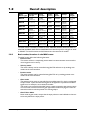
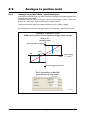
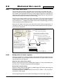
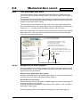
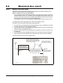
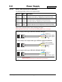
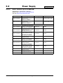
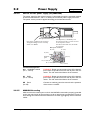
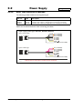
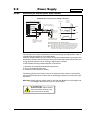
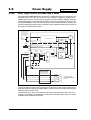
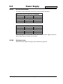
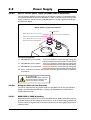
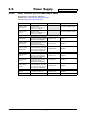
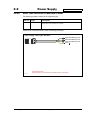
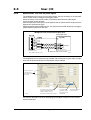
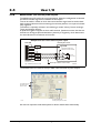
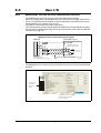
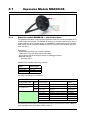
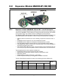
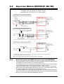
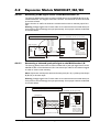
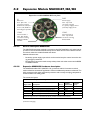
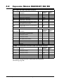
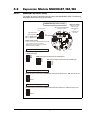
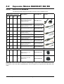
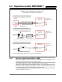
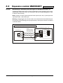
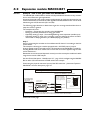
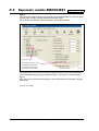
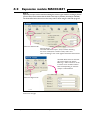
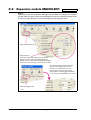
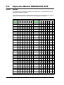
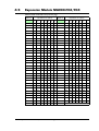
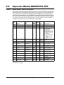
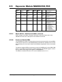
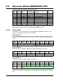
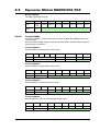
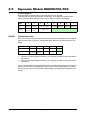
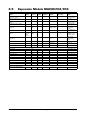
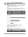
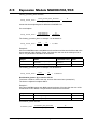
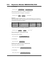
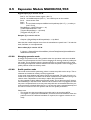
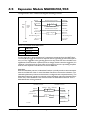
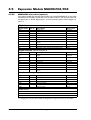
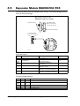
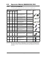
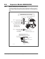
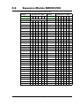
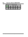
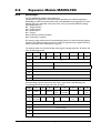
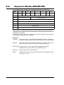
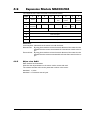
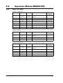
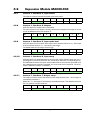
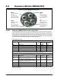
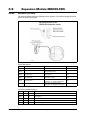
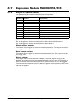
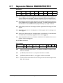
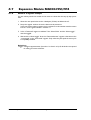
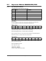
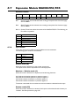
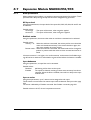
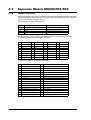
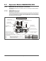
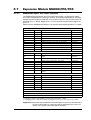
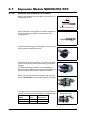
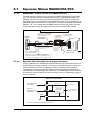
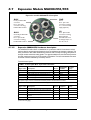
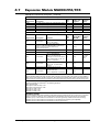
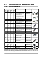
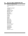
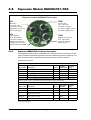
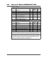
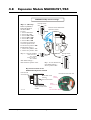
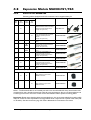
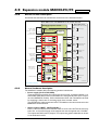
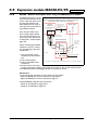
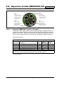
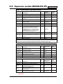
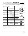
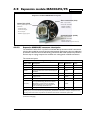
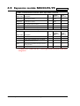
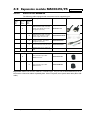
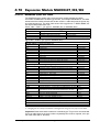
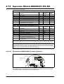
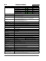
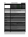
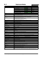
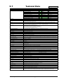
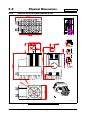
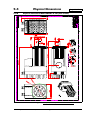
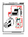
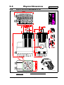
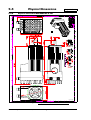
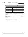
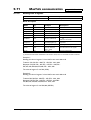
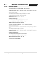
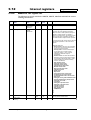
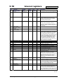
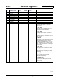
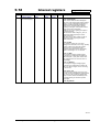
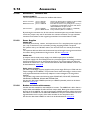
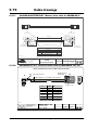
4.2
Expansion Module MAC00-B1/B2/B4
“IO” - Basic I/O’s. M12 - 8pin male connector.
Signal name
Description
Pin no.
JVL Cable
WI1000-M12
F8T05N
A+
Multifunction I/O terminal A+
1
White
1
A-
Multifunction I/O terminal A-
2
Brown
1
B+
Multifunction I/O terminal B+
3
Green
1
B-
Multifunction I/O terminal B-
4
Yellow
1
O1
Digital output 1 - PNP output
5
Grey
1
O2
Digital output 2 - PNP output
6
Pink
1
OCM
Ground intended to be used together with the
other signals in this connector.
7
Blue
1
AIN
Analogue input +/- 10V or used for Zero search
Use the OCM terminal (pin 7) as ground for the
analogue input.
8
Red
1
Isolation
group
“COM1” - Communication connector 1. M12 - 8pin female connector.
Description
Pin no.
JVL Cable
WI1000-M12
M8T05N
Not used
1
White
RS232: TX
RS232 interface. Transmit terminal
Leave open if unused.
2
Brown
1
RS232: RX
RS232 interface. Receive terminal
Leave open if unused.
3
Green
1
GND
Ground intended to be used together with the
other signals in this connector,
4
Yellow
1
RS485: B+
RS485 interface. Leave open if unused
5
Grey
1
RS485: A-
RS485 interface. Leave open if unused
6
Pink
1
Not used
7
Blue
Not used
8
Red
Signal name
Isolation
group
“COM2” - Communication connector 2. M12 - 5pin female connector
Signal name
Description
Pin no.
JVL Cable
WI1000M12
M5T05N
RS232 Rx
RS232 interface receive terminal.
Leave open if unused
1
Brown
1
RS232 Tx
RS232 interface transmit terminal.
Leave open if unused
2
White
1
RS485 B+
RS485 interface. Leave open if unused
3
Blue
1
RS485 A-
RS485 interface. Leave open if unused
4
Black
1
GND
Interface ground (same as main ground).
5
Grey
1
For complete drawings of the M12 cables please see the appendix
Cable drawings, page 396.
130
JVL Industri Elektronik A/S - User Manual - Integrated Servo Motors MAC050 - 3000
Isolation
group