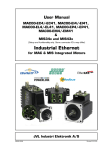
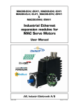
1
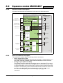
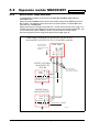
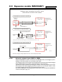
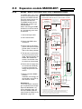
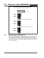
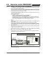
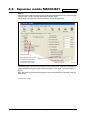
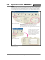
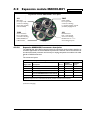
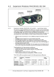
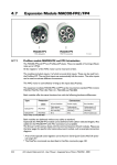
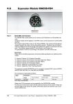
4.3
Expansion module MAC00-B41
Only MAC400 to 3000
MAC00-B41
seen from rear side
TT1133GB
4.3.1
Expansion module MAC00-B41 — overall description.
The expansion module MAC00-B41can ONLY be mounted in the MAC400 and
newer versions of the MAC800 motor (serial numbers >85000).
Please notice that the module CAN NOT be used in the MAC050 to 141 motors.
This module is among the simplest and lowest cost modules in the product range.
The modules contain no intelligence (microprocessor) meaning that all functionalety
is controlled via the basic motor.
The MAC00-B41expansion module offers an industrial interface (M12 connectors)
and a number of feature enhancements, including:
•
•
•
•
•
Standard M12 connectors for optimum reliability
Optical isolated communication covering RS232, RS485 and USB (2.0)
Full RS232 protocol support for use with standard serial cable.
Full RS485 protocol support for multipoint communication up to 100m.
6 high speed I/O channels that individually can be used as inputs or outputs. Each
channel can (when used as output) source up to 300mA.
• Dual supply. The main supply can be removed but the control circuitry is kept active
and position data and communication are still functional.
• Standard M12 connectors for optimum reliability
Typical applications for these expansion modules are:
• Closed loop systems with an overall controller involved.
• Replacement for pneumatic cylinders using the “Air Cylinder mode”
• Dispenser systems.
• Machine adjustment/setup by sending RS232 or RS485 commands.
• Standalone PLC with userprogram stored in the basic motor.
JVL Industri Elektronik A/S - User Manual - Integrated Servo Motors MAC050 - 3000
133
4.3
Expansion module MAC00-B41
4.3.2
Overall hardware description
All internal and external main connections can be seen in the illustration below.
Only MAC400 to 3000
Basic MAC motor with MAC00-B41 module inserted.
MAC00-B41 expansion module
Power supply
P+ : (MAC400) +12-32V
CVI : (MAC400) +12-32V
P+
P-
Fuse F10A
Power ground (P-) is not connected in the MAC00-B41 module
or Zero search input
±10V nom. or up to 32V
Multifunction I/O 1
Multifunction I/O 2
GND
A1+/A2+/B2+/-
CVO
IO1
High speed I/O’s
2
AIN1/2
B1+/-
IO2
IO3
MAC400 any SN
or MAC800 with SN>85000
P+
P-
Power supply
Control
Supply
CVI
Self healing fuse
Itrip = 750mA
2 Analogue inputs
Basic MAC motor
AIN1/2 Analogue input
GND
2
Overvoltage
protection
and
Dipswitch
setup
Multifunction I/O 1
(Bidirectional)
2
A2+/B2+/-
Multifunction I/O 2
(Bidirectional)
Not used
O1
O2
Status outputs
(-)
I/O channel
(Bidirectional)
2
PNP Output
source driver
or
Input
A1+/B1+/-
2
IO4
IO5
IO6
GND
RS485 Termination dipswitch
RS485 Interface
(Isolated)
A
2 channel
differential
Transceiver
RX
TX
B
GND
Asynchronous
interface
Interface
isolation
Tx
RS232 Interface
(Isolated)
Rx
Asynchronous
serial interface
IGND
TT1136GB
4.3.3
134
General hardware description
The MAC00-B41 module offers the following external connections.
• Power supply (P+/P-/CVI)
These terminals are used for the main supply of the motor. A voltage between +12
and 32VDC (MAC400, MAC800, MAC1500 and MAC3000) must be connected.
• Analogue inputs (AIN1 and AIN2)
The analogue inputs are used either as analogue input or digital input. The primary
analogue input is AIN1. When used as analogue input, it can control velocity, torque
or position depending on which mode is set for motor operation. When used for digital inputs, it can be used in position-related modes for the external zero-search sensor. Also in “Air Cylinder Mode” the analogue input is used as a trigger input.
For a functional description, please refer to Analogue input, page 107.
(continued)
JVL Industri Elektronik A/S - User Manual - Integrated Servo Motors MAC050 - 3000
4.3
Expansion module MAC00-B41
Only MAC400 to 3000
• Multifunction I/O 1 and 2 (A1± ,B1± , A2± and B2±)
The functionality of these terminals is the same as for the basic MAC motor. They
can be set up in 3 different configurations.
- Pulse inputs - for functional description please refer to Multifunction I/O used as
pulse inputs, page 111 and General description: “Multifunction I/O” when using a Bx
module, page 124
- Pulse outputs - for functional description please refer to Multifunction I/O used as
pulse outputs, page 112 and
- RS422 interface - for functional description please refer to Multifunction I/O used
as serial communication interface, page 113.
Important !:
Remember to configure “I/O type” as “Pulse Input” in MacTalk if none of the 8 terminals A1/2+, A1/2-, B1/2+ and B1/2- is used (the multifunction I/O’s). This must
be done to avoid random function of the motor since the multifunction I/Os are defined as “Serial data” as default.
• High speed I/O’s (IO1, IO2, IO3, IO4, IO5, IO6, CVO, and GND)
Each of the high speed IO’s can be used as either an input or as an output.
The I/O’s can be read or set from the serial interface (RS232 or RS485) or they can
be operated from the user program stored in the motor.
• RS485 Interface (A-, B+ and GND)
Serial balanced interface for connection to a PC or a controller. The protocol is similar to the RS232 or USB interface, which means that all registers/parameters in the
motor can be monitored or changed. The RS485 is recommended for longer distances or in noisy environments.
• RS232 Interface (Rx, Tx and GND) and USB interface.
Serial unbalanced interface for connection to a PC or a controller. The protocol is
similar to the RS485 interface, which means that all registers/parameters in the motor can be monitored or changed. RS232 is not recommended for long distances
(>10m) and USB is not recommended for distances >2m.
The MAC motor uses “binary” communication protocol which makes it possible to access all the internal registers. Please consult MacTalk communication, page 357 for further
details.
4.3.4
Hardware overview
MAC00-B41 seen from rear side
Interconnect to motor
Contains all internal signals
between module and motor.
Main fuse 10Amp.
Replace only with:
Schurter type
“3402.0040.11”
or
Littlefuse type
“451-10A”
TT1146GB
Setup dipswitch
- Multifunction I/O setup
- RS485 termination
Default switch setting:
Dip1-10 = OFF,ON,OFF,ON,OFF,ON,OFF,ON,OFF,OFF
- Input Ax and Bx for both MF I/O’s are setup for PNP outputs.
- RS485 Termination is disabled.
JVL Industri Elektronik A/S - User Manual - Integrated Servo Motors MAC050 - 3000
135
4.3
4.3.5
Expansion module MAC00-B41
Only MAC400 to 3000
General power supply description
The MAC00-B41 module can be used in the MAC400, MAC800, MAC1500 and
MAC3000 motor.
Notice that only MAC800 motors with serial numbers higher than 85000 support the
B41 module. The diagram below shows how to connect power to a MAC400 motor
mounted with a MAC00-B41.
Please notice that the voltage connected to P+ and/or CVI must stay in the range +1232VDC. Precautions must therefore be taken if the system also contains MAC50, 95, 140
or 141 which may require 48VDC in order to reach maximum motor speed.
See also the general power supply description Power Supply, page 85.
Power supply connections to a MAC140 and a MAC400
mounted with a MAC00-B1, B2 or B4 and B41 modules.
(control voltage)
+12-32VDC
(Bus voltage)
+12-48VDC
Power supply
GND
Make sure that all
involved units are
connected to the same
potential
MAC50-141 Motor
with MAC00-B1,
B2 or B4
Power
Supply
It is recommended
that a separate supply
line is used for each motor.
P+
P-
Control voltage
O+
Only MAC50-141 with
B2 or B4 (Optional)
MAC400 Motor
with MAC00-B41
Power
Supply
Control Volt.
P+
PCVI
Main supply
Max. 32VDC !
Mains 115 or 230VAC
TT1137GB
136
JVL Industri Elektronik A/S - User Manual - Integrated Servo Motors MAC050 - 3000
4.3 Expansion module MAC00-B41
Only MAC400 to 3000
Analogue input connection at the MAC motor
mounted with a MAC00-B41 module.
Connected to a external controller
Position or
velocity
controller
MAC motor
+MAC00-B41
±10V out
Ground
Make sure that all
involved units are
connected to the same
potential
AIN1 (analogue input)
GND (ground)
Screen
Note ! : screen only
connected to signal source.
Connected to a potentiometer
If only 24V supply is available
insert a 2.7k resistor here.
Power supply
10VDC
Screen
2kOhm potentiometer
(JVL typeno. “POT2K”)
MAC motor
+MAC00-B41
Make sure that all
involved units are
connected to the same
potential
AIN1 (analogue input)
GND (ground)
Note ! : screen only
connected to signal source.
This example only covers 0-10V but other configurations do of course also exist, such as 0-5V or +/-10V.
Connected to a zero search switch
MAC motor
+MAC00-B41
Zero search switch
Power supply
10-32VDC
Make sure that all
involved units are
connected to the same
potential
AIN1 (analogue input)
GND (ground)
TT1138GB
Note: Do not apply voltages higher than 32V to the analogue input (AIN)
4.3.6
Using the analogue inputs (AIN1 or AIN2).
When a MAC00-B41 module is mounted in the MAC400 motor, the analogue inputs is
available in the same manner as in the basic motor itself.
The analogue inputs can be used for several applications and the function of the analogue
input is determined by the mode in which the motor is set to operate.
Typically the inputs is used for controlling the velocity, torque or position of the motor
but the input is also used as digital input for Zero search or in “Air Cylinder Mode” where
it is used as trigger input for the movement done by the motor.
For further information concerning physical connections, see the Expansion MAC00-B41
connector description, page 147.
JVL Industri Elektronik A/S - User Manual - Integrated Servo Motors MAC050 - 3000
137
4.3
Expansion module MAC00-B41
4.3.7
RS232 - General description when using the MAC00-B41 module
The RS232 interface is considered the main interface to the RS232 connection between a PC or central controller
to MAC400 with a MAC00-B41 module.
motor when the motor is set
up using the MacTalk winCentral
Make sure that all
Power supply
involved units are
dows software from a PC or
Controller
connected to the same
from any kind of controller us(for example a PC)
potential
ing a RS232 interface.
Opto isolation *
When connecting the RS232
interface to a PC or controller, the following rules must
be followed:
+12-32VDC
GND
Tx
Rx
IGND
Screen connected
to GND in each end
Screen
Note:The basic MAC motor
does not fully support RS232
since the interface signals are
only 5V levels. See also the basic description - Serial interface,
page 106.
Only MAC400 to 3000
MAC400 Motor
with MAC00-B41
Rx
RS232
Tx
Interface
IGND Power P+
Supply P-
Max. 32VDC !
Contr. Voltage CVI
1 Only one motor can be
connected at the interface
Mains 230VAC
Main supply
line. Use the RS485 if multiple units have to be connected at the same time.
2 Use screened cable.
TT1143GB
* Opto isolation is recommended if connection is permanent.
3 Ensure that IGND (interface ground) is also connected.
4 Ensure that all units have a proper connection to safety ground (earth) in order to refer
to the same potential.
5 The RS232 interface cable length should not exceed 10 metres.
Connectors:
To see the specific connector pin-out please see the chapter Expansion MAC00-B41 connector description, page 147.
A finished RS232 cable also exist. Please see Cables for the MAC00-B41, page 149
138
JVL Industri Elektronik A/S - User Manual - Integrated Servo Motors MAC050 - 3000
Only MAC400 to 3000
Screen
1 Use twisted-pair cable
3 Ensure that GND is also
connected.
Power
Supply
P+
P-
Control voltage
Only MAC50-141
with B2 or B4
O+
A
B
GND
(Bus voltage)
+12-48VDC
+12-32VDC
(control voltage)
*** Address=2
RS485
Interface
1 2 3 4 5 6 7 8 9 10
P+
P-
Control voltage
O+
Only MAC50-141 with
B2 or B4 (Optional)
MAC800 Motor
with MAC00-B41
ON
Power
Supply
7 Master Controller RS485
interface:
If available, it is strongly recommended a type with optical isolation is used.
Connectors:
To see the specific connector
pin-out please see the chapter
Expansion MAC00-B41 connector description, page 147.
A finished RS485 cable also
exist. Please see Cables for the
MAC00-B41, page 149
*** Address=1
RS485
Interface
MAC50-141
with B1, B2 or B4
5 The last unit in each end of
the network must be terminated. Note that the B1, B2
and B4, B41 modules all
contain a termination resistor which can be activated.
6 Ensure that the supply lines
are connected individually
in order to minimise the
voltage drop between the
motors.
MAC50-141
with B1, B2 or B4
A
B
GND
2 Use screened cable
4 Ensure that all units have a
proper connection to safety
ground (earth) in order to
refer to the same potential.
GND
A
B
IGND
RS485 - General description when using a MAC00-Bx module
The RS485 offers more noiseRS485 network with 2 x MAC140 and 1 x MAC400
immune communication commounted with MAC00-B1, B2, B4 and B41 modules.
pared to the RS232 interface.
Up to 32 motors can be conCentral
Make sure that all
Power supply
involved units are
nected to the same line.
Controller
connected to the same
The RS485 interface in the
(for example a PC)
potential
MAC00-B41 module is galOpto isolation *
**
vanical isolated.
When connecting the RS485
interface to a central controlScreen connected
ler, the following rules must
to GND in each end
be followed:
Screen
4.3.8
Expansion module MAC00-B41
Screen
4.3
ON
ON
To activate
the termination
set dip 9+10 in
position “ON”
*** Address=3
A **
RS485
B
Interface
IGND Power P+
Supply P-
Max. 32VDC !
Contr. Voltage CVI
Up to 32
Motors
Main supply
Mains 230VAC
TT1144GB
* Opto isolation is recommended.
** The last unit at each end of the line must be terminated. The MAC00-B1, B2
and B4, B41 contain this feature. See the individual module descriptions.
*** Each unit connected must be setup with an address via The MacTalk program.
If only one unit is connected no address is needed.
JVL Industri Elektronik A/S - User Manual - Integrated Servo Motors MAC050 - 3000
139
4.3
Expansion module MAC00-B41
Only MAC400 to 3000
Input type setup for all common output types
The Dip switch is located at the rear side.
Dip-Switch setting
Balanced or "push-pull" output connected
to the A1/2 and B1/2 inputs
NPN
PNP
NPN
B1+ PNP
NPN
Multifunction2
INPUTSETUP
A2+ PNP
NPN
B2+ PNP
1 2 3 4 5 6 7 8
A1+
ON
Multifunction1
INPUTSETUP
OFF
OFF
OFF
OFF
OFF
OFF
OFF
OFF
Dipswitch 9+10 : RS485 termination - see communication chapter
NPN (sink) output connected to the A and B input
NPN
PNP
NPN
B1+ PNP
NPN
Multifunction2
INPUTSETUP
A2+ PNP
NPN
B2+ PNP
1 2 3 4 5 6 7 8
A1+
ON
Multifunction1
INPUTSETUP
ON
OFF
ON
OFF
ON
OFF
ON
OFF
Dipswitch 9+10 : RS485 termination - see communication chapter
PNP (source) output connected to the A and B input
A2+ PNP
NPN
B2+ PNP
1 2 3 4 5 6 7 8
NPN
Multifunction2
INPUTSETUP
ON
NPN
A1+
PNP
Multifunction1
INPUTSETUP B1+ NPN
PNP
OFF
ON
OFF
ON
OFF
ON
OFF
ON
TT1139GB
Dipswitch 9+10 : RS485 termination - see communication chapter
4.3.9
General description: “Multifunction I/O”.
The function of the Multifunction I/O is equal to that of the basic motor with the exception that the B41 module include an overvoltage protection and a dip-switch to set up
what kind of signal source feeds the input (if the Multifunction I/O is set up as inputs).
The illustration above shows how to set up the Multifunction I/O terminals as balanced/
push pull, NPN or PNP input. The illustrations below show examples of connections for
each of these signal types.
140
JVL Industri Elektronik A/S - User Manual - Integrated Servo Motors MAC050 - 3000
4.3
4.3.10
Expansion module MAC00-B41
Only MAC400 to 3000
Connecting an NPN signal source to the Multifunction I/O
The drawing below shows how to connect an NPN source to the MAC00-B41 multifunction I/Os. The diagram shows the A channel. The B channel must be connected in
the same manner. Ensure that the Ax- and Bx- terminals are unconnected in order to
maintain proper function.
Warning: Voltages higher than 5V must under no circumstance be connected directly to
the input since this will damage the input permanently.
NPN (sink) output connected to the A and B input
Dip-Switch setting:
Multifunction 1
INPUT SETUP
A1+
NPN
PNP
NPN
B1+ PNP
NPN
Multifunction 2
INPUT SETUP
A1+ or A2+
A2+ PNP
NPN
B2+ PNP
1 2 3 4 5 6 7 8
Signal source (PLC)
Warning:
Never connect voltages
higher than 5V directly to
the A or B terminals since
this can damage the inputs.
ON
The negative input terminals (Ax- and Bx-)
must be left unconnected.
MAC motor with MAC00-B41 expansion module
ON
OFF
ON
OFF
ON
OFF
ON
OFF
A1- or A2-
NPN
Output
switch
B1+ or B2+
B1- or B2-
Dipswitch 9+10 :
RS485 termination
- see communication chapter
GND
Ground
If used, the B+ terminal must be connected in the same manner as the A+ terminal.
4.3.11
TT1140GB
Connecting a PNP signal source to the Multifunction I/O
The drawing below shows how to connect a PNP source to the MAC00-B41 multifunction I/Os. The diagram shows the A channel. The B channel must be connected in the
same manner.
Ensure that the Ax- and Bx- terminals are unconnected in order to maintain proper function.
Warning: Voltages higher than 5V must under no circumstance be connected directly to
the input since this will damage the input permanently. Use a proper resistor as indicated
in the table below.
PNP (source) output connected to the A and B input
Power
Supply
5-32VDC
+
PNP
Output
switch
Optional
resistor
See table
MAC motor with MAC00-B41 expansion module
Warning:
Never connect voltages
higher than 5V directly to
the A or B terminals since
this can damage the inputs.
Multifunction 1
INPUT SETUP
A1+
NPN
PNP
NPN
B1+ PNP
NPN
Multifunction 2
INPUT SETUP
A1+ or A2+
A2+ PNP
NPN
B2+ PNP
OFF
ON
OFF
ON
OFF
ON
OFF
ON
A1- or A2B1+ or B2+
B1- or B2-
Ground
Dip-Switch setting:
1 2 3 4 5 6 7 8
Signal source (PLC)
Resistor size
0 Ohm (none)
390 Ohm
1 kOhm
1.2 kOhm
1.8 kOhm
2.7 kOhm
3.3 kOhm
ON
Supply:
5VDC
8VDC
12VDC
15VDC
18VDC
24VDC
30VDC
Dipswitch 9+10 :
RS485 termination
- see communication chapter
GND
If used, the B+ terminal must be connected in the same manner as the A+ terminal.
The negative input terminals (Ax- and Bx-) must be left unconnected.
JVL Industri Elektronik A/S - User Manual - Integrated Servo Motors MAC050 - 3000
TT1141GB
141
4.3
4.3.12
Expansion module MAC00-B41
Only MAC400 to 3000
Connecting a balanced/push-pull signal to the Multifunction I/O
The drawing below shows how to connect a balanced or push-pull signal source to the
MAC00-B41 multifunction I/Os. Use twisted-pair cable for the balanced signals in order
to ensure noise immunity.
Note: If inputs are used in pulse-direction format input A (Ax+/Ax-) is pulse input and
input B (Bx+/Bx-) is direction input.
Warning: Voltages higher than 5V must under no circumstance be connected directly to
the input since this will damage the input permanently. Use a proper resistor as indicated
in the table below.
Balanced or push-pull output connected to the A and B input
MAC motor with MAC00-B41 expansion module
A1- or A2-
From internal
Control circuitry
B1+ or B2+
B
B1- or B2GND
Signal GND
Puls/dir
Format
Multifunction 1
INPUT SETUP
A1+
NPN
PNP
NPN
B1+ PNP
NPN
A
Multifunction 2
INPUT SETUP
A2+ PNP
NPN
B2+ PNP
1 2 3 4 5 6 7 8
A1+ or A2+
A
Quadrature
Dip-Switch setting:
ON
External pulse source
Warning:
Never connect voltages
higher than 5V directly to
the A or B terminals since
this can damage the inputs.
OFF
OFF
OFF
OFF
OFF
OFF
OFF
OFF
B
Dipswitch 9+10 :
RS485 termination
- see communication chapter
RS422 outputs (balanced)
Twisted pair cable is recommended
TT1142GB
142
JVL Industri Elektronik A/S - User Manual - Integrated Servo Motors MAC050 - 3000
4.3
4.3.13
Expansion module MAC00-B41
Only MAC400 to 3000
Example - how to use gearmode with MAC00-B41.
The MAC00-B41 module offers a number of I/O possibilities that makes it very convienient to use in Electronic gear applications.
An external encoder with various output configurations can easily be connected to one
of the multifunction I/O channels and also signals like Enable/disable motor can be established using one of I/O terminals (I/O1 to I/O6).
The following pages describe in details how to get the wirering sorted and also how to
setup the motor in general.
The example will cover:
- Hardware : Connecting the encoder to the MAC00-B41
- Setting up relevant parameters for using gear mode
- Optionally setting up input 1 for enabling/disabling motor operation (enable input)
- Optionally setting up input 2 as a “coupling” input for enabling the motor to follow
the encoder or staying stationary at 0 RPM (keeping the position).
Step 1
Start by connecting the encoder to the multifunction IO channel 1 according to the illustration below.
This example is showing an encoder equipped with a 24V PNP (source) output.
A serial resistor must be inserted since the IO channels at the MAC00-B41 is made for
handling RS422 levels which means that no more than 5V must be applied. Higher levels
will be destructive !.
Remember to set the internal dipswitch correctly in order to setup the module to handle
a signal source with a PNP output.
See also General description: “Multifunction I/O”., page 140 for configurering the MAC00B41 to other I/O’s formats than the PNP used in this example.
Concerning the physical connector layout of the IO2 connector - please see Expansion
MAC00-B41 connector description, page 147.
Connecting a 24V PNP (source) encoder to the MAC00-B41 module
MAC motor with MAC00-B41 expansion module
2.7k
Output A
Output B
Ground
IO2 Pin1
A1+
Multifunction1
INPUTSETUP
Multifunction 2
INPUT SETUP
Not used in
this example
A1+
NPN
PNP
NPN
B1+ PNP
NPN
A2+ PNP
NPN
B2+ PNP
1 2 3 4 5 6 7 8
Screened cable is
recommended
Dip-Switch setting:
ON
Incremental encoder
with 24V PNP single
ended output
Warning:
Never connect voltages
higher than 5V directly to
the A or B terminals since
this can damage the inputs.
OFF
ON
OFF
ON
A1 - : Leave unconnected
2.7k
IO2 Pin4
B1+
B1 - : Leave unconnected
IO2 Pin2
Dipswitch 9+10 :
RS485 termination
- see communication chapter
GND
Important ! : The negative input terminals (A1- and B1-) must be left unconnected.
If possible avoid connecting the terminals to the cable since internal capacitances in the cable can interfere
TT1189GB
Continued at next page.
JVL Industri Elektronik A/S - User Manual - Integrated Servo Motors MAC050 - 3000
143
4.3
Expansion module MAC00-B41
Only MAC400 to 3000
Step 2
Now the motor need to be setup in gear mode and the Multifunction I/O 1 must be setup
as pulse input in order to accept the applied encoder signal.
This is done in the MacTalk windows software. See illustration below.
Select gear mode
Select Quadrature input in order
to enable the encoder pulses
at Multifunction IO channel 1
to control the motor motion.
TT1190GB
The desired gear ratio and other relevant motion parameters may also be necessary to
setup. Please see the general gear mode description - Gear Mode - overall description,
page 21
Now the motor should move accordingly to the connected external encoder using the
Gear mode.
Continued at next page.
144
JVL Industri Elektronik A/S - User Manual - Integrated Servo Motors MAC050 - 3000
4.3
Expansion module MAC00-B41
Only MAC400 to 3000
Step 3
Optionally an input can be used for enabling the motor in gear mode or making it passive
(current less) which means that the shaft is not kept in position (the shaft is released).
The illustration below shows how this setup can be done using the MacTalk program.
Select the Advanced tab
Setup as shown
The result will be that input 1 (IO1) is used for selecting
the motor mode (Gear or Passive mode). Index 1 and
Index 2 is refering to the mode registers which are shown below.
The Mode field is found in the lower
part of the register tab. Set the
Mode reg. 1 and 2 as shown in order
to set the motor in Passive mode or
Gear mode depending on the state
of input 1 selected above.
Select the Registers tab
TT1191GB
Continued at next page
JVL Industri Elektronik A/S - User Manual - Integrated Servo Motors MAC050 - 3000
145
4.3
Expansion module MAC00-B41
Only MAC400 to 3000
Step 4
Optionally an input can be used for enabling motor movement according to the external
encoder when the input is active or decelerating the motor to a stationary position when
the input is passive.Setup the motor according to the following illustration.
Select the Advanced tab
Setup as shown
The result will be that input 2 (IO2) is used for
setting the motor speed to 0 RPM (stationary
position) or any velocity above 0 RPM allowing the
motor to move according to the external encoder.
The Velocity field is found in the lower
left part of the register tab. Set the
Velocity 1 to 0 and Velocity 2 to the
desired speed when input 2 is active.
Note that the unit will toggle from RPM
to cnt./smp. when activated by the mouse
Select the Registers tab
TT1192GB
146
JVL Industri Elektronik A/S - User Manual - Integrated Servo Motors MAC050 - 3000
4.3
Expansion module MAC00-B41
Only MAC400 to 3000
Expansion module MAC00-B41 front plate
PWR
IO1
Basic I/O’s
M12 - 8pin male
connector including:
6 I/O’s (IO1 to IO6)
CVO and GND.
Power supply
M12 - 5pin male
connector including:
P+ (primary supply), and CVI
(secondary supply) and P-
COM
IO2
Communication
M12 - 8pin female
connector including:
RS232, RS485 and
USB interface
Extended I/O’s
M12 - 12pin female
connector including:
Multifunction ch. 1 + 2
and 2 analogue inputs
TT1132GB
4.3.14
Expansion MAC00-B41 connector description
The MAC00-B41 offers IP65 protection and M12 connectors which makes it ideal for automation applications where no additional protection is desired. The M12 connectors offer solid mechanical protection and are easy to unplug compared to modules with cable
glands or DSUB connectors.
The connector layout:
“PWR” - Power input. M12 - 5pin male connector
Signal name
Description
Pin no.
JVL Cable
WI1000M12F5T05N
P+
Main supply +12-48VDC. Connect with pin 2 *
1
Brown
1
P+
Main supply +12-48VDC. Connect with pin 1 *
2
White
1
P-
Main supply ground. Connect with pin 5 *
3
Blue
1
CVI
Control and user output supply +12-30VDC.
Connect MAXIMUM 30VDC to this terminal
4
Black
1
P-
Main supply ground. Connect with pin 3 *
5
Grey
1
Isolation
group
* Note: P+ and P- are each available at 2 terminals. Make sure that both terminals are connected in order
to split the supply current in 2 terminals and thereby avoid an overload of the connector.
(Continued next page)
JVL Industri Elektronik A/S - User Manual - Integrated Servo Motors MAC050 - 3000
147
4.3
Expansion module MAC00-B41
Only MAC400 to 3000
“IO1” - Basic I/O’s. M12 - 8pin male connector.
Signal name
Description
Pin no.
JVL Cable
WI1000-M12
F8T05N
Isolation
group
(See note)
I/O1
I/O channel 1 - Can be used as input or output
1
White
1
I/O2
I/O channel 2 - Can be used as input or output
2
Brown
1
I/O3
I/O channel 3 - Can be used as input or output
3
Green
1
I/O4
I/O channel 4 - Can be used as input or output
4
Yellow
1
I/O5
I/O channel 5 - Can be used as input or output
5
Grey
1
I/O6
I/O channel 6 - Can be used as input or output
6
Pink
1
CVO
Supply output. Connected internally to the CVI
terminal in the PWR connector.
DO NOT connect >30V to this terminal !
7
Blue
1
GND
Ground intended to be used together with the
other signals in this connector.
8
Red
1
“COM” - Communication connector - M12 - 8pin female connector.
Signal name
Description
Pin no.
JVL Cable
WI1000-M12
M8T05N
Isolation
group
(See note)
USB: D-
USB interface. Negative data terminal
1
White
2
RS232: TX
RS232 interface. Transmit terminal
Leave open if unused.
2
Brown
2
RS232: RX
RS232 interface. Receive terminal
Leave open if unused.
3
Green
2
IGND
Isolated interface ground to be used together
with the other signals in this connector,
4
Yellow
2
RS485: A-
RS485 interface. Leave open if unused
5
Grey
2
RS485: B+
RS485 interface. Leave open if unused
6
Pink
2
USB: D+
USB interface. Positive data terminal
7
Blue
2
USB: VBUS
USB interface. Supply input 5VDC nominal
8
Red
2
Isolation
group
(see note)
“IO2” - I/O connector 2. M12 - 12pin female connector
148
Signal name
Description
Pin no.
JVL Cable
WI1009M12
M12T05N
A1+
Multifunction I/O1 terminal A1+
1
Brown
1
GND
Ground intended to be used toghether with the
other signals in this connector
2
Blue
1
A1-
Multifunction I/O1 terminal A1-
3
White
1
B1+
Multifunction I/O1 terminal B1+
4
Green
1
A2+
Multifunction I/O2 terminal A2+
5
Pink
1
B1-
Multifunction I/O1 terminal B1-
6
Yellow
1
B2+
Multifunction I/O2 terminal B2+
7
Black
1
A2-
Multifunction I/O2 terminal A2-
8
Grey
1
5VO
5V out - max 100mA
9
Red
1
B2-
Multifunction I/O2 terminal B2-
10
Violet
1
AIN1
Analogue input1 ±10V or used for Zero search
11
Grey/pink
1
AIN2
Analogue input2 ±10V
12
Red/blue
1
JVL Industri Elektronik A/S - User Manual - Integrated Servo Motors MAC050 - 3000
4.3
Expansion module MAC00-B41
4.3.15
Cables for the MAC00-B41
The following cables equipped with M12 connector can be supplied by JVL.
MAC00-B41 Connectors
Description
JVL Order no.
X
RS232 Interface cable. Connects
directly from MAC00-B41 to a PC
Length: 5m (197 inch)
RS232-M12-1-5-8
X
RS485 Interface cable. Connects
directly from MAC00-B41 to a PC
with a RS485 Com. port.
Length: 5m (197 inch)
RS485-M12-1-5-8
X
USB Interface cable. Connects
directly from MAC00-B41 to a PC
with a USB Com. port.
Length: 5m (197 inch)
USB-M12-1-5-8
X
Cable (Ø5.5mm) with M12 female
5-pin connector loose wire ends
0.35mm² (22AWG) and foil screen.
Length: 5m (197 inch)
WI1000-M12F5T05N
X
Same as above but 20m (787 inch)
WI1000-M12F5T20N
X
Cable with M12 male 12 pin
straight connector, loose wire ends.
WI1009-M12M12T05N
X
Same as above but 20m (787 inch)
WI1009-M12M12T20N
X
Cable with M12 female 8pin
straight connector, loose ends.
WI1000-M12F8T05N
X
Same as above but 20m (787 inch)
WI1000-M12F8T20N
X
Cable with M12 male 8-pin
connector loose wire ends
0.22mm² (24AWG) and screen.
Length: 5m (197 inch)
WI1000-M12M8T05N
X
Same as above but 20m (787 inch)
WI1000-M12M8T20N
“IO1”
8pin
male
“IO2”
12pin
Female
“COM”
8pin
Female
Only MAC400 to 3000
Picture
“PWR”
5pin
Male
(picture comming soon)
Protection caps. Optional if connector is not used to protect from dust / liquids.
X
X
X
X
IP67 protection cap for M12
female connector.
WI1000-M12FCAP1
IP67 protection cap for M12
male connector.
WI1000-M12MCAP1
Important: Please note that the cables are a standard type. They are not recommended for use in cable chains or where the cable is repeatedly bent. If this is required, use a special robot cable (2D or 3D
cable).
JVL Industri Elektronik A/S - User Manual - Integrated Servo Motors MAC050 - 3000
149