1
ARGUS GSM
Communication Module
Installation, Programming and User Manual
C
GUARANTEE
During the guarantee period the manufacturer shall, at its sole discretion, replace or repair any defective
product when it is returned to the factory. All parts replaced and/or repaired shall be covered for the remainder of the original guarantee, or for ninety (90) days, whichever period is longer. The original purchaser shall
immediately send manufacturer a written notice of the defective parts or workmanship, which written notice
must in all cases be received prior to expiry of the guarantee.
INTERNATIONAL GUARANTEE
Foreign customers shall enjoy the same guarantee rights as those enjoyed by any customer in Bulgaria,
except that manufacturer shall not be liable for any related customs duties, taxes or VAT, which may be payable.
GUARANTEE PROCEDURE
This guarantee will be granted when the appliance in question is returned. The manufacturer shall accept no
product whatsoever, of which no prior notice has been received.
CONDITIONS FOR WAIVING THE GUARANTEE
This guarantee shall apply to defects in products resulting only from improper materials or workmanship,
related to its normal use. It shall not cover:
• Damages resulting from improper transportation and handling;
• Damages caused by natural calamities, such as fire, floods, storms, earthquakes or lightning;
• Damages caused by incorrect voltage, accidental breakage or water; beyond the control of the manufacturer;
• Damages caused by unauthorized system incorporation, changes, modifications or surrounding objects;
• Damages caused by peripheral appliances unless such peripheral appliances have been supplied by the
manufacturer;
• Defects caused by inappropriate surrounding of installed products;
• Damages caused by failure to use the product for its normal purpose;
• Damages caused by improper maintenance;
• Damages resulting from any other cause, bad maintenance or product misuse.
In the case of a reasonable number of unsuccessful attempts to repair the product, covered by this guarantee, the manufacturer’s liability shall be limited to the replacement of the product as the sole compensation
for breach of the guarantee. Under no circumstances shall the manufacturer be liable for any special, accidental or consequential damages, on the grounds of breach of guarantee, breach of agreement, negligence,
or any other legal notion.
WAIVER
This Guarantee shall contain the entire guarantee and shall be prevailing over any and all other guarantees,
explicit or implicit (including any implicit guarantees on behalf of the dealer, or adaptability to specific purposes), and over any other responsibilities or liabilities on behalf of the manufacturer. The manufacturer does
neither agree, nor empower, any person, acting on his own behalf, to modify or alter this Guarantee, nor to
replace it with another guarantee, or another liability with regard to this product.
UNWARRANTED SERVICES
The manufacturer shall repair or replace unwarranted products, which have been returned to its factory, at
its sole discretion under the conditions below. The manufacturer shall accept no products for which no prior
notice has been received.
The products, which the manufacturer deems repairable, will be repaired and returned. The manufacturer
has prepared a price list and those products, which can be repaired, shall be paid for every repaired appliance.
The closest equivalent product, available at the time, shall replace the products manufacturer deems irreparable. The current market price shall be charged for every replaced product.
!
Attention: The entire manual should be carefully read! This manual contains information on
limitations regarding the product use and functions, as well as information on the limitations
as to liability of the manufacturer.
2
Contents
PART: INSTALLATION
1. General Information.............................................................................................................4
1.1 General Functional Characteristics..............................................................................4
1.2 General Technical Characteristics...............................................................................4
2. Functional Diagram.............................................................................................................5
3. Basic Elements....................................................................................................................5
3.1 Contents of the Equipment..........................................................................................5
3.2 Components of the ARGUS GSM Module...................................................................6
4. Connection Diagrams for Alarm and Fire Control Panels....................................................8
5. Initial Power Up...................................................................................................................10
6. Reset Function....................................................................................................................10
7. Service Function for Checking the Signal Strength.............................................................10
PART: PROGRAMMING
8. Specialized ProsTE software - Parameters programming..................................................12
8.1 Menu “General Settings”..............................................................................................13
8.2 Menu “Inputs/Outputs”.................................................................................................15
8.3 Menu “Phones”............................................................................................................16
8.4 Menu “SMS”.................................................................................................................17
PART: USER
9. Recording and listening to voice messages........................................................................18
9.1 Recording voice messages for alarm events...............................................................18
9.2 Recording of general voice message..........................................................................18
9.3 Listening to recorded voice messages........................................................................18
9.4 Algorithm for sending of voice and SMS messages....................................................19
9.5 Messages for service events.......................................................................................19
10. “Gateway” Mode................................................................................................................20
11. Changing and Checking of the Current State of
Programmable Input / Output via a telephone call or SMS message......................................20
11.1 Changing the current state of a device......................................................................20
11.2 Checking the current state of a device.......................................................................20
11.3 GSM module type answers after current device status check...................................20
12. Checking the Current Signal Strength via SMS................................................................21
NOTES....................................................................................................................................22
3
PART: INSTALLATION
1. General Information
ARGUS is a universal GSM module providing telephone line monitoring and communication
channel for GSM network (as a back-up) in case of main PSTN telephone line failure (loss) or no
telephone line run to the site.
The GSM module can be used for monitoring and control of auxiliary devices - fire or burglar
alarm panel, as and for Home Automation control.
The ARGUS communication module is suitable for applications in homes, residential houses,
apartments, offices and other industrial or public buildings. The GSM module provides 24-hour
protection of the site - burglar and/or fire alarm events.
1.1 General Functional Characteristics
• 8 programmable I/O1 - 6 inputs / outputs, 2 outputs;
• Record of 7 voice messages - 6 for the module status and 1 general for site identification, all
can be recorded via telephone set;
• Record of 8 SMS messages - 6 for the module status, 1 general for site identification, 1 test for
status indication 2;
• 3 service SMS messages - main power supply lost (back-up battery power supply only), main
power supply restored and low charge level of back-up battery;
• Record of 8 telephone numbers, up to 20 symbols each2;
• GSM module available for all popular GSM working frequencies;
• Telephone line monitoring and simulation of it if the line is not available;
• Status indication;
• Back-up of the communication channel and possibility for remote control from the user;
• Independent memory for the programmed data;
• Service function for checking the signal strength.
1
2
I/O - General Purpose Input/Output
Via ProsTE software
1.2 General Technical Characteristics
• Main power supply - 9 - 30VDC / 0.5А, reverse polarity protection;
• Back-up power supply - 4 х 1.2V, NiMH batteries, size “АА” (not included);
• Battery charge current - 0.2 A DC;
• Current consumption:
- Normal (stand-by) mode - 50 mA
(up to 100 mA at PSTN line simulation and according the used telephone);
- Communication (GSM) mode - up to 1.3 А.
• Time for filtration of signals incoming at I/O - 0.5 sec;
• 2 standard connectors RJ11 (Phone and Line) for connecting of telephone and PSTN line;
• Frequency range 850 / 900 / 1800 / 1900 MHz;
• SIM interface - built-in;
• Antenna - connector SMA 50Ohm, 3m long cable;
• Standard RS232 interface for PC connection.
4
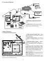
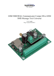
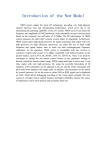
2. Functional Diagram
1 - PSTN Line - General communication
channel for connection with the control
panel.
2 - GSM network - Back-up communication channel for connection with the control
panel in case of PSTN line failure.
3. Basic Elements
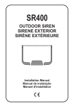
3.1 Contents of the Equipment
1. Small universal plastic box - base
and cover with built light pipe for module
status indication.
2. ARGUS GSM module - see the description of module elements in item
3.2.
3. Back-up power supply - battery
holder for 4 NiMH batteries, size “АА”.
Note: The batteries are not supplied in
the kit.
4. Antenna with a 3m flexible cable.
Note: Install the antenna away from
any electromagnetic and radio sources,
which could cause interference and incorect working of the GSM module!
!
! ATTENTION: Do not route the antenna cable where it could be pinched in
doors, windows etc.
After choosing the antenna place for installation, the manufacturer recommends to position it at 45º angle to ensure an optimal signal
receiving from the GSM cell tower.
5
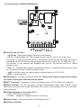
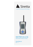
3.2 Components of ARGUS GSM Module
B Terminal row (see the )
• ± 9-30 Vdc - Main power supply (from the control panel);
• I/O 1-6 - Programmable I/O. The terminal must be used for input or for output only!
The Inputs 1-6 are realized with “pull-up” 10k resistors to the main power supply and can be
loaded with up to 30V external voltage, digital filtration 0.5s, low level <1V, high level >3V.
The Outputs 1-6 are realized with transistor with “pull-up” 10k resistors and up to 100mA
ground current.
• Out 7, 8 - Programmable outputs with general purpose - realized with transistor with “pullup” 10k resistor and up to 500mA ground current;
• +AUX - Auxiliary output for power supply of external devices, 9-30V, 0.5A;
• GND - Common ground.
C SIМ Interface - a holder to insert the SIM card. Observe the shown on the picture orientation when inserting the SIM card into the holder!
D ВАТТ Connector - Connector for the built-in battery pack (4х1.2V, NiMH “АА” batteries).
E RS232 Interface - For PC connection; use the communication cable “cable ProsTE” a standard cable (produced from Teletek Electronics JSC, which is not included in the set of the delivered equipment).
F Standard telephone connectors RJ11.
• LINE - PSTN line connecting
• PHONE - Telephone / telephone station connecting
G Reset Jumper – the reset function is described in item 6.
H Antenna connector.
6
I Status Indication LEDs.
• LED1 (red) - Service LED.
LED 1
Green
Red
Indication
Description
Blinking
Normal operation mode.
Lights on
1. Recording or listening of voice messages; GSM module is
activated; programming with ProsTE software.
2. The RESET jumper is set on for loading default parameters;
3. Activated service function for checking the signal strength.
• LED 2 (red-green) - Module status LED.
LED 2
Green
Indication
Description
Blinking at ranGSM module initialization is in progress (the SIM card is acceptdom time interval ed); the module communication with GSM network is running.
Lights on
The module is in normal operation mode; PSTN line is available;
GSM network back-up ready.
Orange
Lights on
PSTN line is not available; GSM network only.
Red
Lights on
GSM module initialization failed (the SIM card is missing; active
PIN code for verification); no PSTN line available.
Off
Lights off
GSM module initialization failed (the SIM card is missing; active
PIN code for verification); PSTN line available.
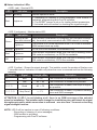
• LED 3 (yellow) - Shows the signal strength. The installer counts the number of flashes over
7 seconds interval. Indication is visible only when the cover is removed and has the following
meaning:
Flashes
Signal
Strength, dBm
Description
☼
Bad
< - 95
The connection is unstable or impossible.
☼☼
Low
- 95 ÷ -85
The connection is unstable but possible.
Good
- 83 ÷ -73
The connection is stable, rare drops of signal
are possible.
Very Good
> - 73
The connection is stable, no problem sending
voice and SMS messages.
☼☼☼
☼☼☼☼
ATTENTION: If LED 3 is not blinking at all, there is no GSM coverage at the selected
place for installation. The installer must change the installation place and check the signal
strength again until a stable connection is achieved - see also item 7 for service checking
signal strength function.
NOTE: LED 3 will be inactive in case of following conditions:
- Recording or listening of voice messages;
- GSM module is activated;
- Programming with ProsTE software.
7
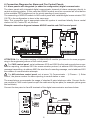
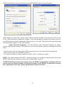
4. Connection Diagrams for Alarm and Fire Control Panels
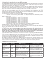
4.1. Alarm panels with integrated (or added to configuration) digital communicator.
The alarm panels with integrated digital communicator transmit all alarm messages directly to
central monitoring station. In this case the ARGUS module must be connected as a first device
to the available PSTN telephone line for priority sending of event reports.
The connecting of ARGUS module to AVA control panel with installed digital communicator CPC
100 TE in the configuration is done in the same way.
Note: This connection type is appropriate when the system is monitored directly from a central
station via SIA, Contact ID, etc protocol.
Example connection diagram between ARGUS module and CA62 control panel:
ATTENTION: For the proper working of GSM ARGUS module you have to do some programming in the engineering menus of the control panel.
! For CA62 control panel, set at addresses 6010 and 6020 the first and second phone numbers for reporting, at address 6011 the communication protocol, at address 6002 the period for
message transmitting, at address 6003 the start time for sending message, and at address 6001
the number of communication attempts.
! For AVA wireless control panel, set at menu “9) Communicator - 1) Phones - 1) Enter
Phone”, the phone number for alarm reporting to central station or user.
The manufacturer recommends the usage of standard 2 pairs telephone cable. Connect the Argus module to CA62 control panel as split the cable wires by two pairs (for example yellow-green
and red-black).
Connect the two pairs to A and B terminals of the digital communicator as shown below:
8
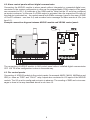
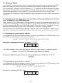
4.2. Alarm control panels without digital communicator.
Connecting the ARGUS module to alarm panels without integrated or connected digital communicator in the system configuration is done as the programmable PGM outputs of the panel
are connected to I/O (1-6) terminals of the GSM module. Note that the I/O must be configured
as inputs in advance. In this case if a PGMх output is activated, then the respective I/Ox input of
the module is activated too - the module sends both SMSx message (typed in the menu 4.SMS
of ProsTE software - see item 8.4) and recorded voice message for alarm events at I/Ox (see
item 9.1).
Example connection diagram between ARGUS module and VEGA6 control panel:
The connecting of ARGUS module to AVA control panel without installed digital communicator
CPC 100 TE in the configuration is done in the same way.
4.3. Fire control panels.
Connecting of ARGUS module to fire control panels (for example MAG2, MAG4, MAG8plus and
IRIS) is done as “FIRE” and “FAULT” relay outputs are connected to I/O inputs of the ARGUS
module. The I/O must be configured as inputs in advance. The sending of SMS and voice messages is done in the way described above in sub item 4.2.
9
5. Initial Power Up
- Insert the SIM card into your mobile phone and disable the PIN check option.
- Check the power supply of the GSM module - both main power supply from the control
panel and back-up power supply MUST BE OFF.
- Mount the GSM module at place where there is a good coverage of the used GSM network that will guarantee the reliable and normal work of the GSM module.
- Insert the SIM card into the GSM PCB holder as observe the position - see item 3.2.
ATTENTION: Always observe the power supplies to be off when you put or remove the SIM
card from the GSM PCB holder!
- Power up the control panel and then switch on the back-up power supply.
- Wait until the GSM module initialization is running - during 10-40 sec. LED 2 is random blinking.
- Check the signal strength by observing the LED 3 blinking. If necessary, change the antenna
position to obtain the possible best level of the signal - see the LED 3 table on page 7.
- The module is in normal operation mode - LED 1 is blinking in green.
- Record voice messages and program other parameters.
6. Reset Function
This function is for restoring of the default parameters of the module set by the manufacturer.
Follow the steps to reset the GSM ARGUS module parameters:
- Power off the module – switch off the main power supply and the batteries.
- Set a jumper on the terminal RESET.
- Power on the module - switch on the main power supply and the batteries - LED1 lights in red.
- Remove the jumper from the terminal RESET.
- Wait 10 to 15 seconds.
- The module is in normal operation mode - LED 1 is blinking in green.
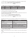
7. Service Function for Checking the Signal Strength
This function is for checking the signal strength from installer to determine the most propriety
place for installation the module. To use this function you need a notebook with USB port, cable
ProsTE and Convertor cable USB-RS232. Follow the steps to check the signal strength:
- The module is in normal operation mode - LED 1 is blinking in green.
- Connect the cable ProsTE to RS232 interface connector of the module (see position 4, item
3.2); connect the cable ProsTE to the notebook using the cable converter.
- Set a jumper to RESET terminal - LED 1 lights on in red.
- Check the signal strength using Terminal program in ASCII mode.
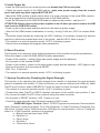
• WINDOWS Hyper Terminal. Select: START-Programs-Accessories-CommunicationHyper Terminal to open the program. Go to File-Properties. In “New Connection Properties“ window at the “Connect using:” field choose free COM port for communication. Click on “Configure”
button. In “COM Properties” window do the settings:
Z Bits per second (baud rate): 9600
Z Data bits: 8
Z Parity: None
Z Stop bits: 1
Z Flow control: None
10
COM Port settings screens examples, using WINDOWS Hyper Terminal Program:
Select “Apply” and next “OK” button in the “COM Properties” window. Then select the “OK” button
in the “New Connection Properties“ window. After connecting the installer can monitor the current GSM signal strength, measured in dBm at every 7 seconds. The levels of the signal strength
are described on page 7 in the LED3 details.
• Other Terminal Programs. You can use any other Terminal Programs for checking the GSM Signal strength. The condition is to use the same connection settings mentioned
above.
- Find the place with the most strong GSM signal and mount the module and the antenna.
- Remove the jumper from RESET terminal.
- The module returns to normal operation mode - LED 1 is blinking in green.
NOTE: If by some reasons, the LED 1 continue lighting on in red after removing the jumper from
RESET terminal, the module must be reset as describes in item 6.
ATTENTION: Always remove the jumper from the RESET terminal after ending the service
checking of the signal strength. Leaving the jumper on the RESET terminal will increase
the consumption and may cause unpredictable module behavior!
11
PART: PROGRAMMING
8. Specialized ProsTE software - Parameters programming
ProsTE is specialized software for programming of control panels and modules produced by
Teletek Electronics JSC company.
The communication is thought a serial connection port of the microcontroller. Use the communication cable “cable ProsTE” (connected to a one of the PC COM ports):
There are two ways for programming the GSM module:
1. All parameters are programmed in advance and then the configuration can be directly write
down to the GSM module.
2. Reading the current GSM module configuration, make changes and write down the new configuration to the GSM module.
ProsTE software gives the installer the possibility to make a database with TDF files (Teletek
Data File) for different GSM module configurations.
Programming of ARGUS GSM Module via ProsTE Software
Connect the ARGUS GSM Module to a communication port of the local computer. Use the cable
“Cable ProsTE”.
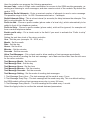
Run the ProsTE with file “ProgrammingSoftwareTeletekElectronics.Desktop.exe”.
Now you see the main window of ProsTE software. The window is divided into two basic parts.
Check the Language Menu for your language. To change the current language open the language window and select the new one. Confirm with the OK button. The program will restart with
the new language set.
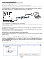
Choose the System and with right click follow → Add → Argus. The programming menus for
GSM ARGUS module now appear as a tree structure at the left part of the window - Figure 1.
Figure 1.
12
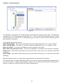
Now choose Argus → Read. A screen “Read” appears - Figure 2.
Enter the number of the communication port in
field Com Port – this is the communication port
to which the GSM module is connected. Do not
change any other parameters in that screen!
Confirm your choice with OK button. Now the
program needs an access code to connect with
the GSM module. By default the access code is
“7777” - Figure 3.
Confirm your choice with OK button - it is necessary to wait a couple of minutes until the connection process is running.
Figure 2.
Figure 3.
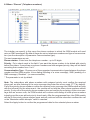
8.1 Menu “General Settings”
Figure 4 - Menu “General Settings” with default parameters
13
Here the installer can program the following parameters:
Access Code - enter a 4-digit code combination for access to the GSM module parameter, recording and listening to voice messages, and also remote control of the module. By default the
code is 7777.
Maximum Redial Attempts - Enter a maximal number of attempts to send a voice message.
The possible range is from 1 to 255. Recommended value - 3 attempts.
Redial Attempts Delay - This is a time interval (in seconds) for delay between the attempts. This
field is not accessible for the user.
Prefix to Add - Choose a prefix number (phone code of a local city), which automatically to be
added in front of the telephone number.
Prefix to Strip - Choose a prefix number (phone code), witch will be ignored, for example exit
from a central telephone station.
Enable prefix strip - Put a check mark in the field if you want to activate the “Prefix to strip”
parameter.
Setting the real time clock of the micro controller:
Year - Set the year (example: 10 - 2010, etc.)
Month - Set the month
Date - Set the day
Hours - Set the hour
Minutes - Set the minutes
Seconds - Set the seconds
Allow Test Messages - Put a check mark to allow sending of test messages periodically.
Enter the period for sending the first test message - set a date and time later than the set ones
for the micro controller:
Test Message Month - Set the month
Test Message Date - Set the day
Test Message Hours - Set the hour
Test Message Minutes - Set the minutes
Test Message Seconds - Set the seconds
Test Message Setting - Set the mode of sending test messages:
1. Test Message Every Hour - The test message will be send at every 1 hour.
2. Test Message Every Day - The test message will be send every day. This is a default setting the GSM module will send test message every day, in every 24 hours.
3. Test Message Every Month - The test message will be send every 1 month.
Select the Apply button to confirm the entered data and parameters.
14
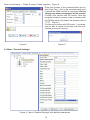
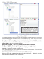
8.2 Menu “Inputs/Outputs”
Figure 5.
The installer can program the I/O parameters, according the number of the input. The submenu
numbers from 1 to 6 correspond to terminals I/O 1 - I/O 6 on the PCB terminal row, and 7 and 8
correspond to Out 7 and Out 8. The programming is the same for all I/O, as the installer sets the
input status for activation.
The possible input status can be:
Input, Rising Edge - The input is activated, when the signal rises from 0 to 1 (Low to High).
Input, Falling Edge - The input is activated, when the signal falls from 1 to 0 (High to Low).
Input, Any Edge - The input is activated at every change of the signal.
Input, does not generate events - The input is disabled, no activation if the signal is changed.
Output Low - Input with normal state low level (the state of the input is 0 in operation and after
resetting).
Output High - Input with normal state high level (the state of the input is 1 in operation and after
resetting).
Select the Apply button to confirm the entered data for the selected I/O number.
You can also use the Apply Selected button if you want to set the programmed parameters of
one I/O for others - a new screen appears, where you can choose the numbers of that inputs /
outputs, to which you want to apply the same programming.
15
8.3 Menu “Phones” (Telephone numbers)
Figure 6.
The installer can specify in this menu the phone numbers to which the GSM module will send
voice or SMS messages. By default there are set no telephone numbers and type of communication (see the description of parameter Communication type).
The next parameters are set:
Phone number - Enter here the telephone number - up to 20 digits.
Priority - Put a check mark in the field if you want the phone number to be dialed with priority
before the others. If more than one phone numbers are with assigned priority, they will be dialed
according their number from 1 to 8.
Communication Type - Choose one of the suggested communication types between the phone
number and the GSM module: Voice dialing (sending of a voice message), SMS (sending of a
SMS message), Disabled * (no communication).
* The parameter is set by default.
Note: The subscribers with phone numbers with assigned priority must confirm the received
phone call, as after listening to the voice message they enter the access code (7777 by default).
If all of the priority phone numbers confirm the received voice message the GSM module will stop
with the informing for the alarm event - the module will not dial the other phone numbers without
priority. If only one of the priority phone numbers does not confirm the receiving of the voice message with an access code, the GSM module will continue with dialing all other phone numbers
including and the ones without priority check mark. After the programmed time, the GSM module
will dial to this priority phone number again and will continue until the subscriber confirms the call
or the “Maximum redial attempts” value is reached.
Select the Apply button to confirm the programmed data for the selected phone number.
16
8.4 Menu “SMS” (SMS messages)
The manufacturer strongly recommends every SMS message to end with
an empty space, so the user can delimit
the separate messages in case there
are several alarm events at the site!
Figure 7 - Menu “SMS”.
The installer enters here the contents of the SMS messages, which will be send to users in case
of service or alarm event. Submenus from 1 for 6 correspond to I/O1 - I/O6, and on the 7th position the general SMS messages is entered - includes information for the site and the owner.
The contents for the service SMS messages can be freely changed in the “SMS Common Settings” field (some texts for the SMS messages are set by default):
General SMS 0 - Type text for General message
Main Power down SMS - Type text for Message for main power supply lost
Main Power OK SMS - Type text for Message for main power supply restored
Low Battery SMS - Type text for Message for low charging level of the battery
Test SMS - Type text for Message for system test
Every SMS message must not be longer than 20 symbols, including spaces. The Latin letters
(а-z, A-Z) and digit (0-9) can be used.
Select the Apply button to confirm the entered texts for SMS messages.
When you finish the programming, select with right click Argus → Upload to write (upload) the new configuration to the GSM module.
17
PART: USER
9. Recording and listening to voice messages
You can record and listening to voice messages when the PSTN line is disabled (disconnected)
or the module is working in “Gateway” mode. Recording and listening to voice messages can be
done via connected telephone set to connector “Phone” (ARGUS PCB) or to the communicator
of the control panel.
ATTENTION: You can also record and listen to voice messages directly via your mobile phone
set, but in this case every try for recording / listening would be charged according your prepaid
plan.
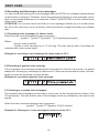
9.1 Recording voice messages for alarm events.
Select from the connected telephone set in sequence:
{symbol “*”}{code 7777}{symbol “*”}{I/O number}{message2},
Where:
1
Access code by default.
2
Dictate a voice message up to 7,5 sec long. The start and the end of recording are
indicated with a short sound signal.
Example for recording a voice message for alarm event at I/O 1:
9.2 Recording of general voice message.
This is a general voice message including basic information for the site or the owner. It is played
always first, following by a message for alarm event. If there are several alarm events, the messages for them will be played one after another.
Example for recording a general voice message:
9.3 Listening to recorded voice messages.
The recorded voice messages can be listen to one by one, as the user selects the number of the
I/O input/output. The start and the end of the message record are indicated by two short sound
signals.
Select from the connected telephone set in sequence:
{symbol “*”}{code 7777}{symbol “#”}{I/O number}
Example for listening to a voice message for alarm event on I/O 1:
18
9.4 Algorithm for sending of voice and SMS messages.
The GSM ARGUS module sends voice and/or SMS messages every time when there is a change
in the state of any input or change of the system parameters – main power supply lost, charge /
discharge of the battery pack, ending of a test period.
When more than one I/O are activated at the same time, the GSM module starts sending the
respective voice / SMS messages in joint pack: general + messages for alarm events. The messages are sent first to telephone numbers set with priority and then to all the rest.
When the two communication types (SMS and voice messages) are programmed, the GSM
module first will send all SMS messages, as starts with the telephone numbers set with priority
and then sends the respective voice messages.
The algorithm for sending voice messages / SMS messages is as follows:
- General voice message/ general SMS - It is played always first, followed by a message for alarm event;
- Message No1/SMS No1 - when I/O 1 is activated;
- Message No2/SMS No2 - when I/O 2 is activated;
- Message No3/SMS No3 - when I/O 3 is activated;
- Message No4/SMS No4 - when I/O 4 is activated;
- Message No5/SMS No5 - when I/O 5 is activated;
- Message No6/SMS No6 - when I/O 6 is activated;
- Test message - when “Allow Test Messages” parameter is enabled (from the ProsTE software) - see the description for “1.General Settings” at item 8.1.
The voice message transfer starts after establishing a real connection thought the telephone
channel, for example after the subscriber accepts the call.
ATTENTION: In case of a service answer from the mobile operator (the subscriber is not
accessible, voice mail, etc), the GSM module will send the voice messages, but will not
rate the call as accepted. The module will rate the call as accepted after a confirmation
with a code (7777 by default) from one or more users set with priority.
If the subscriber rejects the incoming call or does not accept it in 30 sec, the GSM module ARGUS will make a new attempt after a pre programmed time delay. The GSM module will repeat
to send the voice/ SMS messages until a pre programmed number of attempts is reached. After
that the module will stop attempting to reach the user.
All telephone numbers set with priority must confirm the received call, as after listening to the
voice message enter an access code (7777 by default) - see item 8.3. After entering the access
code the user has to wait for confirmation signal from the module for accepting the code.
9.5 Messages for service events
Service Event
Sending
SMS message
Low battery
(<4.8V)
Once
General SMS message + ap- General voice message + 3 appended text “Low Battery!”
pended sound signals „SOS”.
Main power supply lost
Once
General SMS message + apGeneral voice message + 3 appended text “Main Power
pended sound signals “down”
Down”.
Normal operation
mode (restored)
Once
General SMS message + ap- General voice message + 3
pended text “Main Power OK” appended sound signals “up”
Test Message
Once
General voice message + 3
General SMS message + apappended sound signals “sucpended text “Test Message”
cess”
19
Voice message
10. “Gateway” Mode
The “Gateway” is a dialing mode, which allows the user to disconnect the incoming direct PSTN
line and to make a phone call through the available GSM network using the ARGUS module.
You can enter the “Gateway” mode with selecting “***” in sequence as use the telephone keypad.
The user can distinguish the Gateway mode from PSTN line by means a sound signalization - the
GSM module generates 3 sound signals 0.7 second after the start of the free-line signal.
The exit from the “Gateway” mode is automatic, after ending the user call or after a time period
expiration.
11. Changing and Checking of the Current State of Programmable Input / Output
via a Telephone Call or SMS Message
Other function of the GSM module is the possibility to control the programmable inputs. The
user can send commands to change the status of a programmable input via mobile phone call
or SMS message to the SIM card in the GSM module. The control function is possible also via a
telephone set connected directly to the control panel or using the “Gateway” mode.
The commands have the following meaning: 0 (switch over to low level) and 1 (switch over to
high level) – realized with transistor with “pull-up” 10k resistor and up to 500mA ground current.
11.1 Changing the current state of a device
• Via telephone call. Dial the telephone number of the site (the SIM card or PSTN number) and
after GSM module accepts the call, enter in sequence:
{symbol “*”}{code 7777}{I/O number}{new state of the device}
Example for changing the state of I/O 2 from “1” in “0”:
• Via SMS message. Write a new text message from your mobile phone, no spaces included:
{symbol “*”}{code 7777}{I/O number}{ new state of the device}
Example for SMS message contents for changing the state of I/O 8 from “0” in “1”:
*777781
11.2 Checking the current state of a device
• Via telephone call. Dial the telephone number of the site (the SIM card or PSTN number) and
after GSM module accepts the call, enter in sequence:
{symbol “*”}{code 7777}{I/O number}{symbol “#”}
Example for checking the I/O 2 state:
20
• Via SMS message. Write a new text message from your mobile phone, no spaces included:
{symbol “*”}{code 7777}{I/O number}{symbol “#”}
Example for SMS message contents for checking the state of I/O 4:
*77774#
11.3 GSM module type answers after current device status check
Check
Answer type
State “1”
State “0”
Via DTMF
Sound signal
One long sound signal
Two short sound signals
Via SMS
SMS text message
“In x Status 1”
“In x Status 0”
The In x is the number of the respective input / output.
12. Checking the Current Signal Strength via SMS
This option is used from the installer or user to check the current GSM signal strength and to
evaluate the optimal antenna position.
Write a new text message from your mobile phone, no spaces included:
{symbol “*”}{code 7777}{command “1?”}
Example for SMS message contents for checking the signal strength:
*77771?
The GSM module answers with a text message. The SMS format and its description is as follows:
Message
Description
“No signal”
There is no GSM coverage at all. Connection is not
possible.
“RSSI reading failed”
Error occurred while trying to obtain the current
signal strength.
“RSSI level is VERY LOW (-YYY dBm)”
The connection is not possible or will be unstable.
“RSSI level is LOW (-YYY dBm)”
The connection is unstable but possible.
“RSSI level is FAIR (-YYY dBm)”
The connection is stable but drops are possible.
“RSSI level is GOOD (-YYY dBm)”
The connection is stable.
The “YYY” abbreviation represents the exact RSSI signal level, where the worst strength value
is -115dBm, and the best -53dBm.
NOTE: The worst RSSI signal level at which is possible to send at least SMS messages is
-103dBm.
Other information about the signal strength and the expected RSSI levels is explained at item
3.2.
21
NOTES
........................................................................................................................................
........................................................................................................................................
........................................................................................................................................
........................................................................................................................................
........................................................................................................................................
........................................................................................................................................
........................................................................................................................................
........................................................................................................................................
........................................................................................................................................
........................................................................................................................................
........................................................................................................................................
........................................................................................................................................
........................................................................................................................................
........................................................................................................................................
........................................................................................................................................
........................................................................................................................................
........................................................................................................................................
........................................................................................................................................
........................................................................................................................................
........................................................................................................................................
........................................................................................................................................
22
NOTES
........................................................................................................................................
........................................................................................................................................
........................................................................................................................................
........................................................................................................................................
........................................................................................................................................
........................................................................................................................................
........................................................................................................................................
........................................................................................................................................
........................................................................................................................................
........................................................................................................................................
........................................................................................................................................
........................................................................................................................................
........................................................................................................................................
........................................................................................................................................
........................................................................................................................................
........................................................................................................................................
........................................................................................................................................
........................................................................................................................................
........................................................................................................................................
........................................................................................................................................
........................................................................................................................................
23
18020728, Rev.A, 07/2011
www.teletek-electronics.com
Address: 14A Srebarna Str., 1407 Sofia, Bulgaria
tel.: (+359 2) 9694 800, fax: (+359 2) 962 52 13
e-mail: [email protected]