1
LT70-868 Terminal User Guide
1VV0301096 Rev.0 – 24/10/2013
LT70-868 Terminal User Guide
1VV0301096 Rev.0 – 24/10/2013
This document is related to the following product:
PRODUCT
LT70-868 Terminal
Reproduction forbidden without Telit Communications S.p.A. written authorization - All Rights Reserved
page 2 of 24
LT70-868 Terminal User Guide
1VV0301096 Rev.0 – 24/10/2013
DISCLAIMER
The information contained in this document is the proprietary information of Telit Communications S.p.A.
and its affiliates (“TELIT”). The contents are confidential and any disclosure to persons other than the
officers, employees, agents or subcontractors of the owner or licensee of this document, without the prior
written consent of Telit, is strictly prohibited.
Telit makes every effort to ensure the quality of the information it makes available. Notwithstanding the
foregoing, Telit does not make any warranty as to the information contained herein, and does not accept
any liability for any injury, loss or damage of any kind incurred by use of or reliance upon the information.
Telit disclaims any and all responsibility for the application of the devices characterized in this document,
and notes that the application of the device must comply with the safety standards of the applicable
country, and where applicable, with the relevant wiring rules.
Telit reserves the right to make modifications, additions and deletions to this document due to
typographical errors, inaccurate information, or improvements to programs and/or equipment at any time
and without notice. Such changes will, nevertheless be incorporated into new editions of this document.
Copyright: Transmittal, reproduction, dissemination and/or editing of this document as well as utilization
of its contents and communication thereof to others without express authorization are prohibited.
Offenders will be held liable for payment of damages. All rights are reserved.
Copyright © Telit Communications S.p.A. 2013.
Reproduction forbidden without Telit Communications S.p.A. written authorization - All Rights Reserved
page 3 of 24
LT70-868 Terminal User Guide
1VV0301096 Rev.0 – 24/10/2013
CONTENTS
CHAPTER I. INTRODUCTION ..................................................................................................................................... 5
I.1. AIM OF THE DOCUMENT ............................................................................................................................................................................... 5
I.2. REFERENCE DOCUMENTS ............................................................................................................................................................................. 5
I.3. DOCUMENT CHANGE LOG ............................................................................................................................................................................. 6
I.4. GLOSSARY .................................................................................................................................................................................................. 7
CHAPTER II. GENERAL CHARACTERISTICS ........................................................................................................... 8
II.1. GENERAL REQUIREMENTS .......................................................................................................................................................................... 8
II.2. TEMPERATURE CHARACTERISTICS .............................................................................................................................................................. 9
II.3. MECHANICAL CHARACTERISTICS ................................................................................................................................................................. 9
II.4. DC CHARACTERISTICS ............................................................................................................................................................................... 9
II.5. FUNCTIONAL CHARACTERISTICS ................................................................................................................................................................ 10
II.6. DIGITAL CHARACTERISTICS....................................................................................................................................................................... 13
II.7. ORDERING INFORMATION .......................................................................................................................................................................... 13
II.8. ACCESSORIES ......................................................................................................................................................................................... 13
CHAPTER III. MECHANICS AND CONNECTION .....................................................................................................14
III.1. MECHANICAL CHARACTERISTICS ............................................................................................................................................................. 14
III.2. CONNECTIONS ....................................................................................................................................................................................... 15
III.3. CABLES DESCRIPTION ............................................................................................................................................................................ 17
CHAPTER IV. ANNEXES ...........................................................................................................................................19
IV.1. TERMINALS’ INSTALLATION: PRINCIPLES AND CAUTIONS ............................................................................................................................. 19
IV.2. CONNECTION TO A RS422 OR RS485 INTERFACE ..................................................................................................................................... 20
IV.3. TERMINAL REFLASHING ............................................................................................................................................................................ 21
IV.4. ETSI 300 220-2 VERSION 2.4.1 STANDARDS (SUMMARY) .......................................................................................................................... 22
IV.5. DECLARATIONS OF COMPLIANCE .............................................................................................................................................................. 24
Reproduction forbidden without Telit Communications S.p.A. written authorization - All Rights Reserved
page 4 of 24
LT70-868 Terminal User Guide
1VV0301096 Rev.0 – 24/10/2013
CHAPTER I.
INTRODUCTION
I.1. Aim of the Document
The aim of this document is to present the Hardware features and the application of LT70-868 radio terminal. The
characteristics will be described within three distinct chapters:
-
"General characteristics" describes the electrical and mechanical characteristics.
"Mechanics and connections" details the casing, connector, cabling and power supply.
-
The Software functionalities are described in the reference document [5], listing the operating modes,
registers and their use.
I.2. Reference documents
[1] EN 300 220-2 v2.4.1
[2] ERC Rec 70-03
[3] 2002/95/EC
[4] LE70-868 module : User Manual
[5] Star Network Protocol : User Manual
[6] SR Manager Tool: User Guide
ETSI Standards for SRD , May 2012
ERC Recommendation for SRD, October 2012
Directive of the European Parliament and of the Council, 27 January 2003
1vv0301037_Telit_xE70_868_RF_Module_User_Guide
1vv0300873_Telit_Star_Network_Protocol_Stack_User_Guide
1vv0300899_Telit_SR_Manager_Tool_User_Guide
Reproduction forbidden without Telit Communications S.p.A. written authorization - All Rights Reserved
page 5 of 24
LT70-868 Terminal User Guide
1VV0301096 Rev.0 – 24/10/2013
I.3. Document change log
Revision
Date
ISSUE # 0 24/10/13
Changes
First Release
Reproduction forbidden without Telit Communications S.p.A. written authorization - All Rights Reserved
page 6 of 24
LT70-868 Terminal User Guide
1VV0301096 Rev.0 – 24/10/2013
I.4. Glossary
ACP
BER
Bits/s
CER
dBm
EMC
EPROM
ETR
ETSI
FM
FSK
GFSK
GMSK
IF
ISM
kbps
LBT
LNA
MHz
PLL
PROM
NRZ
RF
RoHS
RSSI
Rx
SRD
Tx
SMD
VCO
VCTCXO
Adjacent Channel Power
Bit Error Rate
Bits per second (1000 bits/s = 1Kbps)
Character Error Rate
Power level in decibel milliwatt (10 log (P/1mW))
Electro Magnetic Compatibility
Electrical Programmable Read Only Memory
ETSI Technical Report
European Telecommunication Standard Institute
Frequency Modulation
Audio Frequency Shift Keying
Gaussian Frequency Shift Keying
Gaussian Minimum Shift Keying
Intermediary Frequency
Industrial, Scientific and Medical
kilobits/s
Listen Before Talk
Low Noise Amplifier
Mega Hertz (1 MHz = 1000 kHz)
Phase Lock Loop
Programmable Read Only Memory
Non return to Zero
Radio Frequency
Restriction of Hazardous Substances
Receive Strength Signal Indicator
Reception
Short Range Device
Transmission
Surface Mounted Device
Voltage Controlled Oscillator
Voltage Controlled and Temperature Compensated Crystal Oscillator
Reproduction forbidden without Telit Communications S.p.A. written authorization - All Rights Reserved
page 7 of 24
LT70-868 Terminal User Guide
1VV0301096 Rev.0 – 24/10/2013
CHAPTER II.
GENERAL CHARACTERISTICS
II.1. General Requirements
The LT70-868 terminal is a multi-channel radio terminal, delivering up to 500mW in the 868MHz ISM band
(unlicensed frequency band).
It allows ‘point-to-point’, `multipoint’ or ‘mesh’ functioning modes.
The “ERC recommendation 70-03” describes the different usable sub-bands in the 868MHz license free band, in
terms of bandwidth, maximum power, duty cycle and channel spacing. It gives the following limitations:
ERC recommendation 70-03
Band
Frequency band
(MHz)
Annex1 g3
869.4 - 869.65
Maximum radiated
power (mW)
500
Channel spacing
(KHz)
25 or wideband
Duty cycle
(%)
10
This band is free to use but the terminal and the user must respect the 10% duty cycle limitation. This means that
each terminal is limited to a total transmit time of 6 minutes per hour. It is the responsibility of the user to respect it.
Furthermore, the terminal complies with the ETSI 300-220-2 v2.4.1 (specific for SRD). The main requirements are
described in chapter IV.3.
Finally, the terminal complies with the new European Directive 2002/95/EC concerning the Restrictive Usage of
Hazardous Substances (RoHS).
National Restrictions for non specific SR devices Annex 1 band g3:
Country
Band g3
Georgia
Russian
Federation
Ukraine
Restriction
Reason/Remark
Not implemented
Not implemented
Not implemented
Reproduction forbidden without Telit Communications S.p.A. written authorization - All Rights Reserved
page 8 of 24
LT70-868 Terminal User Guide
1VV0301096 Rev.0 – 24/10/2013
II.2. Temperature Characteristics
Minimum
Typical
Maximum
Unit
- 40
25
+ 85
°C
75
%
+ 85
°C
95
%
Operating
Temperature
Relative humidity
20
Storage
Temperature
- 40
Relative humidity
25
0
II.3. Mechanical Characteristics
Characteristics
Connectors
Unit
Connection using terminal blocks inside the casing. Exit
through cable gland
Dimensions Box
100x66x47
Antenna length :
• Removable antenna version
LEDs
mm
mm
90
No LEDs are available
II.4. DC Characteristics
6V
12V
40V
Unit
210(*)/TBD/TBD
105(*)/TBD/TBD
32(*)/TBD/TBD
mA
Reception consumption
16(*)
8(*)
< 3(*)
mA
Stand-by consumption
< 2(*)
< 1(*)
< 0.3(*)
µA
Characteristics
Transmission consumption
500mW / 100mW / 25mW
(*): Typical, not misured
Reproduction forbidden without Telit Communications S.p.A. written authorization - All Rights Reserved
page 9 of 24
LT70-868 Terminal User Guide
1VV0301096 Rev.0 – 24/10/2013
II.5. Functional characteristics
ERC Rec 70-03
Band g3: 869.400 MHz - 869.650 MHz
Frequency Band
RF data rate
1.2 kbps
2.4 kbps
4.8 kbps
9.6 kbps
19.2 kbps
38.4 kbps 57.6 kbps
1
Numbers of channels
Channel width
250 kHz
Channel 0
869.525 MHz
Total Bandwidth
250 kHz
Transmission
Duty cycle
≤ 10%
Modulation Format
2GFSK
Deviation
± 0.6 kHz
± 1.2
kHz
± 7 kHz ± 7 kHz
Frequency tolerance
at 25°C
± 10 kHz
± 20 kHz
± 30 kHz
+/- 2.5 kHz
Selectable by software
(see Protocol Stack User Guide [5])
RF Output Power
at 3.6V
From +15 dBm to +27dBm
Reception
Rx filter BW
Sensitivity
for PER < 0.8
20 kHz
20 kHz
20 kHz
27 kHz
44 kHz
81 kHz
122 kHz
TBD
TBD
-117dBm
-115dBm
-113dBm
-110 dBm
-108dBm
Reproduction forbidden without Telit Communications S.p.A. written authorization - All Rights Reserved
page 10 of 24
LT70-868 Terminal User Guide
1VV0301096 Rev.0 – 24/10/2013
ERC Rec 70-03
Band g3: 869.400 MHz - 869.650 MHz
Frequency Band
RF data rate
1.2 kbps
2.4 kbps
4.8 kbps
9.6 kbps
19.2 kbps
38.4 kbps 57.6 kbps
1
Numbers of channels
Channel width
250 kHz
Channel 0
869.525 MHz
Total Bandwidth
250 kHz
Transmission
Duty cycle
≤ 10%
Modulation Format
2GFSK
Deviation
± 0.6 kHz
± 1.2
kHz
± 7 kHz ± 7 kHz
Frequency tolerance
at 25°C
RF Output Power
at 3.6V
± 10 kHz
± 20 kHz
± 30 kHz
+/- 2.5 kHz
Selectable by software
(see Protocol Stack User Guide [5])
From +15 dBm to +27dBm
Reception
Rx filter BW
15KHz
Sensitivity [dBm]
for PER < 0.8
-115; -117; -116
Ch1-Ch5-Ch10
Reproduction forbidden without Telit Communications S.p.A. written authorization - All Rights Reserved
page 11 of 24
LT70-868 Terminal User Guide
1VV0301096 Rev.0 – 24/10/2013
Indiano Frequency Band: 865 MHz - 867 MHz
RF data rate
4.8 kbps
19.2 kbps
9.6 kbps
38.4 kbps
10
Numbers of channels
Channel width
200 kHz
Channel 0
865.1 MHz
Total Bandwidth
2 MHz
Transmission
Modulation Format
Deviation
2GFSK
± 7 kHz
± 10 kHz
± 7 kHz
Frequency tolerance
at 25°C
± 20 kHz
+/- 2.5 kHz
Selectable by software
(see Protocol Stack User Guide [5])
RF Output Power
at 3.6V
From +15 dBm to +27dBm
Reception
Rx filter BW
Sensitivity [dBm]
for PER < 0.8
20 kHz
27 kHz
44 kHz
81 kHz
-117
-115
-113
-110
Reproduction forbidden without Telit Communications S.p.A. written authorization - All Rights Reserved
page 12 of 24
LT70-868 Terminal User Guide
1VV0301096 Rev.0 – 24/10/2013
II.6. Digital Characteristics
Function
Characteristics
µC
Serial link
•
128 kB + 8 kB in system programmable flash
•
8 kB RAM
•
2 kB E2PROM
•
RS232 TTL Full Duplex
•
1200 to 115200 bps
•
7 or 8 bits
•
Parity management
•
Flow control
o Hardware (RTS/CTS)
•
Embedded software
functionality
Flexibility:
o Pre flashed
o Customization capability
o Embedded bootloader for firmware download through serial
link or over the air
II.7. Ordering information
The appropriate Telit part number you need to order LT868-Terminal is 3990150524.
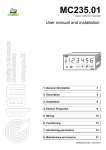
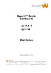
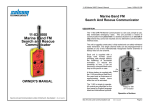
II.8. Accessories
The LT868-Terminal box could be integrated with two wall fastening lugs FIBOX MRS-28540 (product number
7028540):
Reproduction forbidden without Telit Communications S.p.A. written authorization - All Rights Reserved
page 13 of 24
LT70-868 Terminal User Guide
1VV0301096 Rev.0 – 24/10/2013
CHAPTER III.
MECHANICS AND CONNECTION
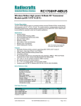
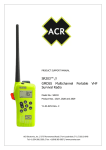
III.1. Mechanical Characteristics
IP67 Casing
• Mechanical Drawings
Reproduction forbidden without Telit Communications S.p.A. written authorization - All Rights Reserved
page 14 of 24
LT70-868 Terminal User Guide
1VV0301096 Rev.0 – 24/10/2013
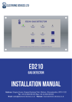
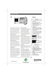
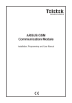
III.2. Connections
The terminal will communicate with the host through a cable connected to a matching connector on the mother
board inside the casing (yellow part on the following drawing):
TxD, RxD:
Serial link signals in RS232 format. TxD is for the data going out of the Terminal
while RxD is for the data coming into the Terminal. The logic '1' is represented by
signal between –3 and –15V.
CTS:
Clear To Send: signal into the Terminal. Indicates if the Terminal can send serial
data to the User (Active on ‘0’, +3V to +15V) or not (Inactive on ‘1’, -15V to -3V).
RTS:
Request To Send: signal going out of the Terminal. Indicates that the user can
transmit serial data (Active on ‘0’, +3V to +15V) or not (Inactive on ‘1’, -15V to -3V).
DTR:
Stand-By signal into the Terminal. Switches the Terminal in Low-Power Mode ('1',
-15V to -3V) or in Normal Mode ('0', +3V to +15V).
RS232-485:
Used with the S215 Register, selects the type of serial link: open for RS232
(default, internal pull up 100 KΩ), GND for RS422 or RS485. Can be also made by
RS232/485 switch.
A, B, Y, Z:
RS422/RS485 signals.
For RS422 use A (or Rx+), B (or Rx-), Y (or Tx+) and Z (or Tx-).
For RS485, use only A (or D+) and B (or D-).
Reproduction forbidden without Telit Communications S.p.A. written authorization - All Rights Reserved
page 15 of 24
LT70-868 Terminal User Guide
1VV0301096 Rev.0 – 24/10/2013
6-40V:
6 to 40 VDC power supply. There is no internal ON/OFF switch for the power
supply. The switch off capability should be external.
Internal LED:
- Green Led: it is switch on when the terminal is transmitting data
- Red Led: it is switch on when the terminal is receiving data
Reproduction forbidden without Telit Communications S.p.A. written authorization - All Rights Reserved
page 16 of 24
LT70-868 Terminal User Guide
1VV0301096 Rev.0 – 24/10/2013
III.3. Cables Description
The associated cable is connected to the matching connector of the mother board and goes out of the terminal
through a cable gland. The cable must be shielded and have an external diameter between 3.5 and 7mm. The
conductors must have a cross section of 0.22mm² (24AWG).
• Case of RS-232
Connector
(8 points)
Name
Terminal Side
Color
Connector
Sub-D
(9 points)
Name
PC/Automate Side
1
TxD (Transmit Data)
Blue
RxD (Receive Data)
2
2
RxD (Receive Data)
White
TxD (Transmit Data)
3
3
CTS (Clear To Send)
Brown
RTS (Request To Send)
7
4
RTS (Request To Send)
Yellow
CTS (Clear To Send)
8
5
DTR (Data Terminal Ready)
Green
DTR (Data Terminal Ready)
4
6
RS232/422-485
Orange
Open
7
Gnd (ground)
Black
Gnd (ground)
8
Vcc (6 to 40V)
Red
Vcc (6 to 40V)
Reproduction forbidden without Telit Communications S.p.A. written authorization - All Rights Reserved
5
page 17 of 24
LT70-868 Terminal User Guide
1VV0301096 Rev.0 – 24/10/2013
• Case of RS-422/485 (FULL DUPLEX):
Connector
(8 points)
Name
Terminal Side
Name
Automate Side
Color
1
Z or Tx- (Transmit Data)
Blue
B or Rx- (Receive Data)
2
A or Rx+ (Receive Data)
White
Z or Tx+ (Transmit Data)
3
B or Rx- (Receive Data)
Brown
Y or Tx- (Transmit Data)
4
Y or Tx+ (Transmit Data)
Yellow
A or Rx+ (Receive Data)
5
DTR
Green
Open
6
RS232/422-485
Orange
Gnd
7
Gnd (ground)
Black
Gnd (ground)
8
Vcc (6 to 40V)
Red
Vcc (6 to 40V)
• Case of the RS-485 (HALF DUPLEX):
Connector
(8 points)
Name
Terminal Side
Name
Automate Side
Color
1
B (Data-)
Blue
B (Data-)
2
open
White
Open
3
open
Brown
Open
4
A (Data+)
Yellow
A (Data+)
5
DTR
Green
Open
6
RS232/422-485
Orange
Gnd
7
Gnd (ground)
Black
Gnd (ground)
8
Vcc (6 to 40V)
Red
Vcc (6 to 40V)
Reproduction forbidden without Telit Communications S.p.A. written authorization - All Rights Reserved
page 18 of 24
LT70-868 Terminal User Guide
1VV0301096 Rev.0 – 24/10/2013
CHAPTER IV.
ANNEXES
IV.1. Terminals’ Installation: Principles and cautions
You must use the power supply and serial cable provided by Telit with the terminal. Take care of
the polarity for the power supply connection (red wire +Vcc, black wire GND).
The ON/OFF switching capability of the power supply is external to the terminal.
The radio environment should be closely studied prior to any installation with a spectrum analyzer
in order to determine whether and where the installation will be optimal.
In case of outdoor installations, IP casings are recommended.
In case of a ceiling installation, the terminal should be mounted upside down for a better radiation
A 1 m distance between two terminals should be respected under 25mW power output, at least 2
m at 100mW and 3m at 500mW.
The terminals should be located as high and as free as possible so that a line of sight
propagation is established between terminals.
The terminal should not be surrounded by metallic masses because of the disturbances caused
by a reflection phenomena.
The electrical disturbances can come from various sources and should be avoided
o
o
o
o
Engines
High current devices
Power relays, transformers
Etc...
The radio disturbances should also be avoided:
o
o
System in the same frequency band such as cars remote control systems.
Systems in a nearby frequency band such as high power (2 W) talkie-walkie systems.
Vibrations and/or shocks can also be source of disturbances. It is therefore advised to mount the
terminals in silent-blocks in order to stabilize it whenever necessary.
Distances, obstacles and weather conditions can strongly affect radio communications and cause
disturbances as well as communication breakdowns.
Reproduction forbidden without Telit Communications S.p.A. written authorization - All Rights Reserved
page 19 of 24
LT70-868 Terminal User Guide
1VV0301096 Rev.0 – 24/10/2013
IV.2. Connection to a RS422 or RS485 interface
LT70-868 terminal is configured in RS232 mode by default (S215=0): it allows connect it directly on a PC
serial port.
To configure the terminal in RS422 or RS485 mode:
Go to Hayes Mode and configure S215 Register:
set to '1' for RS422
set to '2' for RS485 Half Duplex
set to ‘3’ for RS485 Full Duplex
Power Off the terminal.
Connect RS485 or RS422 serial link to the terminal.
Connect RS232-485 pin to GND or set RS232/485 switch to RS485 side.
Power On the terminal.
N.B.: if you power off the board and set RS232-485 pin open, RS485/RS422 is inactivate and RS232 is activate.
Reproduction forbidden without Telit Communications S.p.A. written authorization - All Rights Reserved
page 20 of 24
LT70-868 Terminal User Guide
1VV0301096 Rev.0 – 24/10/2013
IV.3. Terminal reflashing
LT70-868 terminals are re-flashable through the serial link.
In order to re-flash the terminal, switch off the power supply, open the casing, put the “PROG” switch on “ON”
position, and switch on the power supply. Refer to its SR Manager Tool User Guide ([6]) for detailed explanation.
Reproduction forbidden without Telit Communications S.p.A. written authorization - All Rights Reserved
page 21 of 24
LT70-868 Terminal User Guide
1VV0301096 Rev.0 – 24/10/2013
IV.4. ETSI 300 220-2 Version 2.4.1 standards (summary)
Limits allowed by ETSI standard
Transmission
+/- 12.5 kHz @ 25 kHz channelization
+/- 87 kHz (+/-100 ppm) > 25 kHz channelization
Frequency error
ACP for channels
- 37 dBm in 16 kHz “receiver” filter BW under normal test conditions
- 32 dBm in 16 kHz “receiver” filter BW under extreme test conditions
≤ 25 kHz
Reference
Bandwidth (RBW)
Lower envelope
point
Upper envelope
point
Minimum frequency
maximum frequency
1 kHz
- 30 dBm (1 µW)
fe, lower
fe, upper
1 kHz
- 36 dBm (250
nW)
(fe, lower – 200 kHz)
(fe, upper + 200 kHz)
10 kHz
- 36 dBm (250
nW)
(fe, lower – 400 kHz)
(fe, upper + 400 kHz)
100 kHz
- 36 dBm (250
nW)
(fe, lower – 1 MHz)
(fe, upper + 1 MHz)
47 MHz to 74 MHz
7,5 MHz to 118 MHz
174 MHz to 230 MHz
470 MHz to 862 MHz
Other frequencies
below 1 000 MHz
Frequencies above
Operating
- 54 dBm (4 nW)
- 36 dBm (250 nW)
- 30 dBm (1 µW)
Standby
- 57 dBm (2 nW)
- 57 dBm (2 nW)
- 47 dBm (20 nW)
Modulation
bandwidth
Frequency
Unwanted
emissions in the
spurious domain
Limit
State
1 000 MHz
Reception
Frequency offset of the
unwanted signal
Receiver bandwidth
Minimum offset between
wanted and unwanted signals
15 kHz
≥ 35 dB
25 kHz
≥ 33 dB
81 kHz
≥ 28 dB
122 kHz
≥ 26 dB
15 kHz
≥ 60 dB
25 kHz
≥ 58 dB
81 kHz
≥ 53 dB
122 kHz
≥ 51 dB
+/-2 MHz
Blocking for class 2
equipments
+/-10 MHz
Spurious radiation
Below 1000 MHz
Above 1000 MHz
- 57 dBm (2 nW)
- 47 dBm (20 nW)
Reproduction forbidden without Telit Communications S.p.A. written authorization - All Rights Reserved
page 22 of 24
LT70-868 Terminal User Guide
1VV0301096 Rev.0 – 24/10/2013
Examples of propagation attenuation
433 MHz
Loss
Attenuation
Factor
Open office
Window
Thin wall (plaster)
Medium wall (wood)
Thick wall (concrete)
Armoured wall (reinforced concrete)
Floor or ceiling
Armoured floor or ceiling
Rain and/or Fog
0%
<5%
25 %
40 %
50 %
70 %
50 %
70 %
90 %
0 dB
< 1 dB
3 dB
4 – 6 dB
5 – 8 dB
10 – 12 dB
5 – 8 dB
10 – 12 dB
20 – 25 dB
868 MHz
Loss
Attenuation
0%
15 %
35 %
50 %
60 %
80 %
60 %
80 %
95 %
0 dB
1 – 2 dB
3 – 4 dB
5 – 8 dB
9 – 11 dB
12 – 15 dB
9 – 11 dB
12 – 15 dB
25 – 30 dB
Loss
0%
30 %
50 %
70 %
85 %
90 %
85 %
90 %
?? *
2.4 GHz
Attenuation
0 dB
3 dB
5 – 8 dB
10 – 12 dB
15 – 20 dB
20 – 25 dB
15 – 20 dB
20 – 25 dB
?? *
*=
Attenuations increase along with the frequency. In some cases, it
is therefore difficult to determine loss and attenuation value.
Note = The table above is only indicative. The real values will depend on
the installation environment itself.
Reproduction forbidden without Telit Communications S.p.A. written authorization - All Rights Reserved
page 23 of 24
LT70-868 Terminal User Guide
1VV0301096 Rev.0 – 24/10/2013
IV.5. Declarations of Compliance
TBD
Reproduction forbidden without Telit Communications S.p.A. written authorization - All Rights Reserved
page 24 of 24