1
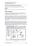
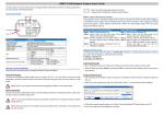
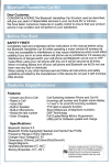
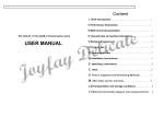
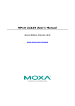
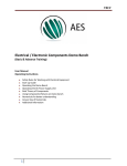
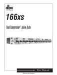
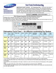
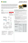
iso685
Installation Bulletin / Reference Guide
TM
This document is intended as a reference guide for installing and using a BENDER iso685 ground fault
detector. This document includes installation, setup, and usage instructions. For complete details,
including installation, setup, settings, and troubleshooting, refer to the complete iso685 user manual.
This document is intended as a supplement and not a replacement to the complete user manual.
Only qualified maintenance personnel shall operate or service this equipment. These instructions
should not be viewed as sufficient for those who are not otherwise qualified to operate or service this
equipment. This document is intended to provide accurate information only. No responsibility is assumed by BENDER for any consequences arising from use of this document.
Installation
Installation (continued)
Mounting
The iso685 is a DIN-rail mounted device. See reverse side for dimensions.
Wiring - Connector X1
The X1 connector provides a series of low-voltage inputs, including digital inputs, connections
to Bender RS-485 bus, and the analog output. Typically, these functions are used for remote
test, remote reset, analog output, and RS-485. The function that these inputs utilize must be
set in the menu. Refer to the menu flow chart on the reverse side for more information. Do not
connect the 24 VDC supply voltage and supply via A1/A2 simultaneously.
Wiring - General
See figure 1 for basic wiring schematic. Line connections
(L1 and L2) may use the schematic below for systems below 793 VAC or 1000 VDC. If a voltage coupler is used
to connect to the system, refer to the complete user
manual for the specific wiring diagram. Use minimum
AWG 24, maximum AWG 12 wire. When wiring is complete, replace the terminal cover, making sure it clicks.
For more information, refer to the iso685 user manual.
In addition to the AC/DC 100-240 V supply voltage via
A1/A2 terminals, the device may also be powered by 24
VDC connected to the X1 connector. Refer to “Wiring Connector X1” for more information. Do not connect
both simultaneously.
! DANGER
HAZARD OF ELECTRIC SHOCK,
EXPLOSION, OR ARC FLASH
Digital interface
• Disconnect all power before servicing.
• Observe all local, state, and national
codes, standards, and regulations.
I1 I2 I3 A B
+ Q1 Q2 M+
X1
3Ø AC System
1Ø AC System
L1
L1
L2
L1/+
L3
L3/-
KE
E
GND
3
US
6A
DC System
L+
4
A1/+
A2/-
L2
L1/+
5
L3/-
KE
E
6
L-
Example wiring for external
test, reset, and standby is
shown to the right. Note that
the correct option must be
set in the menu under “Function” for each digital input.
I1
KE
E
Initial setup
X1
X2
R
11
10
9
11
12
14
21
7
22
24
8
1.
Connection to 1Ø AC system
7.
Alarm relay K1 - SPDT dry contact
2.
Connection to DC system
8.
Alarm relay K2 - SPDT dry contact
3.
Connection to 3Ø AC system
9.
4.
Supply voltage connections (100 - 240
VAC) - 5 A fuses required
Switchable termination resistor - used
when connecting to Bender RS-485 bus
10. Ethernet port (currently inactive)
5.
Line connections to monitored system
6.
Connections to equipment / protective
ground
11. Connector X1 for digital inputs, RS-485,
analog output - see below
Wiring - Contacts
Using a normally closed or normally open contact utilizes two factors: wiring out of the proper
terminal, and setting the respective contact to normally energized or deenergized operation.
Refer to the chart below for relay conditions. Changing the energized state of the contact is
done via the “Relay 1” and “Relay 2” options (option “Mode”) found in the main menu.
Relay operation setting
Device alarm state
Input 1
I2
Input 2
I3
Input 3
A
RS-485 A
B
RS-485 B
+
+24 V
Q1
Output 1
Q2
Output 2
M+
Analog output
I2
I3
A
B
Standby
2
L3/-
I1
Ground
GND
L1/+
Description
L2
GND
1
Terminal
Relay K1 State
+
Reset
Test
M+
Q2
Q1
Initial steps
•
Select the language.
•
Set the date and time.
•
Set the system type - choose “DC” for DC systems, “AC” for single-phase AC systems, and
“3AC” for three-phase AC systems. In systems with power conversion, the system type that
should be selected should be the type at the point that the iso685 is connected.
•
If a voltage coupler is used, select the correct one. Otherwise, select “None.”
Profile selection
Selecting a profile allows for an automatic setup of key system parameters required for operation. Select the profile that closest matches your application. Detailed descriptions of profiles
are listed below. As a general guideline:
•
For standard AC/DC power distribution with no power conversion, select “Power circuits.”
•
For low voltage AC/DC control systems, select “Control circuits.”
•
For systems with small- to mid-size inverters / VFDs, select “Inverter > 10 Hz.”
Select “High capacitance” if your system meets one or more of the following requirements:
•
Very large distribution network (i.e. rated for 2000 A or more)
•
System contains a high quantity of power conversion equipment (inverters / VFDs)
•
The application typically includes high leakage capacitance, such as ships and solar arrays
Refer to the table below. NOTE: “Power conversion” refers to AC/DC or frequency conversion
equipment, including but not limited to rectifiers, inverters, and variable frequency drives
(VFD/ASD).
Profile name
System specs (voltage,
frequency, leak. capacitance)
Application
Power circuits
Up to 690 VAC (15 - 460 Hz)
Up to 1000 VDC
0 - 150 μF
Standard AC and DC power distribution systems with no power
conversion equipment. Suitable for general applications.
Control circuits
Up to 230 VAC (15 - 460 Hz)
Up to 230 VDC
0 - 150 μF
Designed for low-voltage AC/DC control systems with no power
conversion equipment.
Relay K2 State
Power ON, normal state
(no alarms)
11-12 CLOSED
11-14 OPEN
21-22 CLOSED
21-24 OPEN
Power OFF
11-12 CLOSED
11-14 OPEN
21-22 CLOSED
21-24 OPEN
Power ON, alarm state
11-12 OPEN
11-14 CLOSED
21-22 OPEN
21-24 CLOSED
Generator
Up to 690 VAC (15 - 460 Hz)
Up to 1000 VDC
0 - 5 μF
Designed for generator monitoring applications with no power
conversion equipment, as well as systems with an extremely low
leakage capacitance.
Normally energized mode
(N/E)
Failsafe mode
“N/C” in device settings menu
Power ON, normal state
(no alarms)
11-12 OPEN
11-14 CLOSED
21-22 OPEN
21-24 CLOSED
High capacitance
Up to 690 VAC (15 - 460 Hz)
Up to 1000 VDC
0 - 1000 μF
Designed for applications with high leakage capacitances, inlcuding:
very large systems, ships, and solar applications.
Energized in the normal state
Power OFF
11-12 CLOSED
11-14 OPEN
21-22 CLOSED
21-24 OPEN
Inverter > 10 Hz
Up to 690 VAC (10 - 460 Hz)
Up to 1000 VDC
0 - 20 μF
Use this profile when using standard power conversion equipment. If
the system contains a high amount of power conversion equipment,
select “High capacitance” profile.
Power ON, alarm state
11-12 CLOSED
11-14 OPEN
21-22 CLOSED
21-24 OPEN
Inverter < 10 Hz
Up to 690 VAC (1 - 460 Hz)
Up to 1000 VDC
0 - 20 μF
Use this profile when power conversion equipment is used that
continuously runs at an extremely low frequency.
Normally de-energized mode
(N/D)
Non-failsafe mode
“N/O” in device settings menu
Energized in the alarm state
Relay will switch when the
alarm is activated.
Relay will switch when the
alarm is activated, on device
startup, or when power to the
device is lost.
Bender Inc. • USA: 800.356.4266 / 610.383.9200 / [email protected] • Canada: 800.243.2438 / 905.602.9990 / [email protected] • www.bender.org
Document NAE1018021 • 09.2014 • © Bender Inc. • Page 1/1 • Side 1/2
iso685
Installation Bulletin / Reference Guide
TM
Initial setup (continued)
Displays and controls
Alarm value
Alarm values for insulation resistance vary by system due to the type of connected loads and
general system conditions. Adjust the alarm values to appropriate levels based on the system
that is connected to. As a general rule for setting initial alarms, values of 100 Ω/V for the prewarning and 50 Ω/V are recommended. These may be adjusted afterwards as prevailing system comditions warrant.
7
Outputs
Two SPDT contacts are available for alarm outputs. The relays’ energizing behavior is described
in the table “Device relay conditions.” Under the FUNCTION menu option for each relay, the
relay can be set to trip on individually assigned alarms. Each relay and digital output can trigger
on the following:
•
Insulation resistance fault prewarning alarm
•
Insulation resistance fault main alarm
•
Connection error
•
DC- alarm (when a sufficient DC fault is detected on the negative line)
•
DC+ alarm (when a sufficient DC fault is detected on the positive line)
•
Symmetrical alarm (when DC fault(s) are detected with no significant pull on either line)
•
Internal device error
•
Common alarm (activates on any of the above alarms)
•
Device inactive (iso685 is put into standby mode)
9
8
Each relay can trigger up to 3 types. The analog output and buzzer can trigger on insulation
resistance fault only. For the relays to trip on any alarm, set the function to “Common alarm.” For
more information, refer to Figure X (device relay conditions), Figure X (menu flow chart), and
the complete iso685 user manual.
1.
“^” button: Up button, increase value in
menu
2.
“RESET” button: Resets device in
latched mode; “<” button: Back button,
select parameter
Menu structure flow chart
3.
Figure 5 shows the structure of the menu built into the iso685. The menu is used for viewing
alarms, viewing the status of the system, and making any necessary settings changes.
Use the supplied gray boxes to take note of applied settings for future reference. For detailed
descriptions of each menu option, refer to the complete iso685 user manual.
Menu or settings option
4.
“DATA” button: Displays data values; “v”
button: Down button, decrease value in
menu
“MENU” button: Enters main menu;
“ESC” button: Return to previous menu
level
1
4
2
5
3
6
5.
“TEST” button: Activates self-test; “>”
button: Right / forward button, select
parameter
6.
“INFO” button: Displays system information; “OK” button: Confirms values
7.
LED “ON”: Power applied to the device
8.
Alarm LED indicators: SERVICE, 1, 2
9.
Backlit LCD display
Using the iso685
Settings option essential for proper operation
1. Alarm settings
1. Insulation alarm
1. Alarm 1
1 kΩ - 10 MΩ
2. Alarm 2
1 kΩ - 10 MΩ
3. Memory
on / off
2. Profile
See reverse page
3. System type
AC / 3AC / DC
4. Coupling
none / coupler
5. Device
active / inactive
6. t(start)
0 - 120 s
Complete list of features
Consult the iso685 user manual for a complete list of features and instructions for use.
Navigating the device
Use the buttons to the right of the screen to navigate the information screens and the menu. All
button labels are backlit - depending on the current location in the menu, only the usable buttons will be backlit. Not all keypad labels may be visible at once. In the example shown below,
the device is in alarm. Only the usable button labels for that screen are lit.
on / off
7. Coupler monitor.
1/2/3. Digital 1/2/3
8. Inputs
9. Outputs
1/2. Relay 1/2
3/4. Digital 1/2
1. Mode
active high / low
2. t(on)
100 ms - 300 s
3. t(off)
100 ms - 300 s
4. Function
test / reset / standby
1. TEST
2. Relay mode
N/O / N/C
3/4/5. Function 1/2/3
See reverse page
1. TEST
2. Relay mode
active / passive
3/4/5. Function 1/2/3
See reverse page
1. TEST
5. Buzzer
6. Analog
2/3/4. Function 1/2/3
See reverse page
1. Mode
0(4)-20 mA, 0-10V
2. Scale center
linear / 28kΩ / 120kΩ
3. TEST
4. Function
resistance / DC shift
isoGraph - Data trending screen
The iso685 includes the isoGraph features, which provides onboard data trending of the system insulation resistance over time. The isoGraph feature is particularly useful for troubleshooting ground faults into a time frame. To utilize this feature, access it through
2. Data meas. value
3. Control
Data-isoGraph 2
1. TEST
2. RESET
1.0
.100
.010
.001
MΩ
Hour 12:26 12:52
3. Start initial
4. History
5. Device settings
1. Language
2. Clock
3. Interface
1. Address
1. BMS
1 - 150
2. Ethernet
4. Display
1/4
1. Brightness
5. Password
6. Commissioning
7. Service
6. Info
Analog Outputs
Linear option
If a linear analog output is selected, the insulation resistance is 10 kΩ at the high value, and 10
MΩ at the low value, and linerally proportional in between.
Dimensions
Dimensions in inches (mm).
4.25“ (108)
Nonlinear output
If the nonlinear output is selected, it is calculated using the following formula:
3.7“ (93)
10)
4.3“(1
Bender Inc. • USA: 800.356.4266 / 610.383.9200 / [email protected] • Canada: 800.243.2438 / 905.602.9990 / [email protected] • www.bender.org
RF - Insulation resistance in kΩ
A1 - Lower value, analog output (i.e. 0 for 0-20 mA)
A2 - Upper value, analog output (i.e. 20 for 0-20 mA)
A3 - measured analog output value
RSKM - selected midpoint value (28 / 120 kΩ)
Document NAE1018021 • 09.2014 • © Bender Inc. • Page 1/1 • Side 2/2